EP0588570B1 - Soupape - Google Patents
Soupape Download PDFInfo
- Publication number
- EP0588570B1 EP0588570B1 EP19930307160 EP93307160A EP0588570B1 EP 0588570 B1 EP0588570 B1 EP 0588570B1 EP 19930307160 EP19930307160 EP 19930307160 EP 93307160 A EP93307160 A EP 93307160A EP 0588570 B1 EP0588570 B1 EP 0588570B1
- Authority
- EP
- European Patent Office
- Prior art keywords
- valve
- sealing element
- spring
- valve seat
- characteristic
- Prior art date
- Legal status (The legal status is an assumption and is not a legal conclusion. Google has not performed a legal analysis and makes no representation as to the accuracy of the status listed.)
- Expired - Lifetime
Links
Images

Classifications
-
- F—MECHANICAL ENGINEERING; LIGHTING; HEATING; WEAPONS; BLASTING
- F16—ENGINEERING ELEMENTS AND UNITS; GENERAL MEASURES FOR PRODUCING AND MAINTAINING EFFECTIVE FUNCTIONING OF MACHINES OR INSTALLATIONS; THERMAL INSULATION IN GENERAL
- F16K—VALVES; TAPS; COCKS; ACTUATING-FLOATS; DEVICES FOR VENTING OR AERATING
- F16K21/00—Fluid-delivery valves, e.g. self-closing valves
-
- F—MECHANICAL ENGINEERING; LIGHTING; HEATING; WEAPONS; BLASTING
- F16—ENGINEERING ELEMENTS AND UNITS; GENERAL MEASURES FOR PRODUCING AND MAINTAINING EFFECTIVE FUNCTIONING OF MACHINES OR INSTALLATIONS; THERMAL INSULATION IN GENERAL
- F16K—VALVES; TAPS; COCKS; ACTUATING-FLOATS; DEVICES FOR VENTING OR AERATING
- F16K1/00—Lift valves or globe valves, i.e. cut-off apparatus with closure members having at least a component of their opening and closing motion perpendicular to the closing faces
- F16K1/32—Details
- F16K1/34—Cutting-off parts, e.g. valve members, seats
- F16K1/42—Valve seats
-
- F—MECHANICAL ENGINEERING; LIGHTING; HEATING; WEAPONS; BLASTING
- F16—ENGINEERING ELEMENTS AND UNITS; GENERAL MEASURES FOR PRODUCING AND MAINTAINING EFFECTIVE FUNCTIONING OF MACHINES OR INSTALLATIONS; THERMAL INSULATION IN GENERAL
- F16K—VALVES; TAPS; COCKS; ACTUATING-FLOATS; DEVICES FOR VENTING OR AERATING
- F16K25/00—Details relating to contact between valve members and seats
-
- F—MECHANICAL ENGINEERING; LIGHTING; HEATING; WEAPONS; BLASTING
- F16—ENGINEERING ELEMENTS AND UNITS; GENERAL MEASURES FOR PRODUCING AND MAINTAINING EFFECTIVE FUNCTIONING OF MACHINES OR INSTALLATIONS; THERMAL INSULATION IN GENERAL
- F16K—VALVES; TAPS; COCKS; ACTUATING-FLOATS; DEVICES FOR VENTING OR AERATING
- F16K31/00—Actuating devices; Operating means; Releasing devices
- F16K31/004—Actuating devices; Operating means; Releasing devices actuated by piezoelectric means
- F16K31/005—Piezoelectric benders
- F16K31/006—Piezoelectric benders having a free end
-
- Y—GENERAL TAGGING OF NEW TECHNOLOGICAL DEVELOPMENTS; GENERAL TAGGING OF CROSS-SECTIONAL TECHNOLOGIES SPANNING OVER SEVERAL SECTIONS OF THE IPC; TECHNICAL SUBJECTS COVERED BY FORMER USPC CROSS-REFERENCE ART COLLECTIONS [XRACs] AND DIGESTS
- Y10—TECHNICAL SUBJECTS COVERED BY FORMER USPC
- Y10T—TECHNICAL SUBJECTS COVERED BY FORMER US CLASSIFICATION
- Y10T137/00—Fluid handling
- Y10T137/0318—Processes
- Y10T137/0402—Cleaning, repairing, or assembling
- Y10T137/0441—Repairing, securing, replacing, or servicing pipe joint, valve, or tank
- Y10T137/0486—Specific valve or valve element mounting or repairing
-
- Y—GENERAL TAGGING OF NEW TECHNOLOGICAL DEVELOPMENTS; GENERAL TAGGING OF CROSS-SECTIONAL TECHNOLOGIES SPANNING OVER SEVERAL SECTIONS OF THE IPC; TECHNICAL SUBJECTS COVERED BY FORMER USPC CROSS-REFERENCE ART COLLECTIONS [XRACs] AND DIGESTS
- Y10—TECHNICAL SUBJECTS COVERED BY FORMER USPC
- Y10T—TECHNICAL SUBJECTS COVERED BY FORMER US CLASSIFICATION
- Y10T137/00—Fluid handling
- Y10T137/0318—Processes
- Y10T137/0402—Cleaning, repairing, or assembling
- Y10T137/0491—Valve or valve element assembling, disassembling, or replacing
Definitions
- This invention relates to valves and, more particularly, to the sealing of valves during closure.
- Valves are used in many fields for controlling the flow of liquid and gaseous media and throughout this specification and claims, such media will be referred to simply as a fluid or fluids as the context requires.
- valves Numerous forms of valve have been proposed having a valve seat member and a valve closure member movable towards and away from the seat member to close and open the valve to control fluid flow through the valve.
- confronting surfaces of the seat and closure member must be fashioned in strict conformity. Such strict conformity requires, in many instances, accurate machining of the confronting surfaces of the members.
- Piezo electric control valves have also been proposed as substitutes for solenoid controlled valves and are preferable in installations where size and weight are important design considerations.
- Piezo electric control valves may take the form of discs, usually circular, and beams which may be supported at each end or simply, cantilevered.
- piezo electric control valves are in the form of circular discs
- peripheral flatness not infrequently introduces sealing problems. This is principally due to the fact that it is difficult to produce, on a production basis, relatively thin metal discs possessing a sufficiently high degree of flatness to mate with a corresponding flat surface machined or otherwise formed on a valve seat.
- thin metal discs constitute substrates for supporting piezo electric ceramic materials on one or each face of the disc. Examples of such piezo electric valves are described in U.S. patents 4,545,561 and 3,360,664.
- a piezo electric valve for controlling fluid flow, the valve comprising a valve housing, a cavity within the housing, inlet and outlet ducts leading fluid into and out from the cavity, a movable piezo electric valve disc element disposed in the cavity, and means for supporting the valve disc element at a position inwardly of the disc periphery so that upon actuation of the element by a voltaqe applied thereto, the periphery of the disc is displaceable and at least a portion of a peripheral region of the disc serves to control fluid flaw between the inlet and outlet ducts.
- German Patent Publication No. 2253059 which has been taken for the delimitation of claim 1, discloses a lifting valve particularly for use in pulsating rocket engines.
- the lifting valve includes two cooperating sealing surfaces one of which is constituted by a stationary valve seat, and the other of which is constituted by a moveable valve closure member.
- the valve seat consists of hard metal
- the valve closure member consists of a material which is plastically deformable.
- the metal surface comprises a plurality of annular concentric sealing combs around the valve seat bore which are saw toothed shaped in cross-section.
- a valve comprises a valve seat member, a valve member movable towards and away from the valve seat member to close and open the valve; the valve including a sealing element made from a resilient material and attached to one of the valve seat and movable valve members, the sealing element possessing an initial deformable characteristic and a deformed retention characteristic, the initial deformable characteristic being such that initial closure of the valve causes the sealing element to substantially conform to the shape of the other member and the deformed retention characteristic being such as to cause the sealing element to retain the so-conformed shape; characterised in that the sealing element is a multiple component sealing element comprising first and second spring members, the first spring member having lesser resiliently deformable characteristics than the second spring member, and in that the second spring member is disposed more remotely from said one of the valve seat and movable valve members to which the sealing element is attached, and closer to said other member, than said first spring member.
- the movable valve member is preferably in the form of a piezo electric disc comprising a substrate having a layer of piezo ceramic applied to at least one face thereof.
- a method of forming a valve seat for creating a seal against a movable valve member having an irregular surface comprises the steps of:
- the compliant (resilient) elements may be made from any suitable synthetic or natural rubber-like material.
- a material may be chosen to achieve the dichotomous properties in a single component which posses two mechanical states: the first being soft and compliant and the second being semi rigid with the required changes described above being easy to effect yet irreversible.
- a valve seat in accordance with the present invention may from a mechanical point of view be compared to a spring system comprising two dissimilar springs 10, 11 connected in series as shown in FIGURE 1.
- FIGURES 2 and 3 show a piezo electric valve disc 12 centrally supported and in accordance with the invention
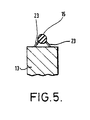
- FIGURES 4 and 5 show alternative sealing arrangements for the valve.
- spring 10 serves to absorb production flatness tolerance of piezo disc 12 (FIGURE 2 ) without radically changing the compression (and, therefore, the sealing force) in the second spring 11.
- the first spring 10 is therefore, compared to the second spring 11 both long and weak.
- the second spring 11 is the normal sealing element and its stiffness is chosen according to well understood design parameters.
- the first spring 14 is a helical compression spring (e.g about 8 mm in length).
- the second spring 15 is a compliant (elastomeric) element of any suitable synthetic or natural rubber like material having a circular cross-section (e.g about 2 mm in diameter).
- both springs 14 and 15 are free to move and accommodate the tolerances in all dependent components such as disc 12 mounted on central 'support 12', and housing 13.
- the second spring 15 has a constant compression (since there is a spatially constant force applied) and, therefore, matches exactly the profile irregularity of the disc 12.
- an adhesive (rigid glue) 17 and, therefore, only the second spring 15 participates in the subsequent sealing operations (see FIGURE 3).
- the maximum compression 18 is typically about 20 microns.
- the valve seat comprises the housing 13, while the sealing element comprises springs 14, 15 and adhesive 17, and the valve disc 12 comprises a movable valve member, having piezo electric activators 19 associated therewith, to effect movement thereof.
- the piezo electric activator 19 preferably comprise a layer of piezo electric ceramic applied to a least one face of disc 12 (both faces in FIGURES 2, 3 and 4),
- the second spring 15 is preferably annular, extending around the periphery of the disc 12, while a plurality of different coil springs 14 may be provided as the first spring.
- the helical (coil) spring 14 of FIGURE 3 has been replaced by a plurality of leaf springs 20 which support second spring 15 which is the form of a ring of circular cross-section.
- springs 20 are locked or otherwise secured to housing 13 by glue 21.
- FIGURE 5 A further form of an equivalent spring arrangement is shown in FIGURE 5 in which the first metal spring elements 23 (about 4 mm in length 25 and 0.4 mm thick) are rigidly connected to housing 13 and second spring 15 after initial deformation.
Landscapes
- Engineering & Computer Science (AREA)
- General Engineering & Computer Science (AREA)
- Mechanical Engineering (AREA)
- Electrically Driven Valve-Operating Means (AREA)
- Lift Valve (AREA)
- Temperature-Responsive Valves (AREA)
- Magnetically Actuated Valves (AREA)
- Glass Compositions (AREA)
- Sealing With Elastic Sealing Lips (AREA)
- Sealing Devices (AREA)
- Superconductors And Manufacturing Methods Therefor (AREA)
Claims (8)
- Soupape comprenant :un élément (13) formant siège de soupape ;un élément de soupape (12) mobile vers et depuis l'élément (13) formant siège de soupape pour fermer et ouvrir la soupape ; la soupape comprenant un élément d'étanchéité (14, 20, 23 ; 15) fabriqué à partir d'un matériau élastique et fixé à l'un des éléments formant siège de soupape et de soupape mobile (13, 12), l'élément d'étanchéité (14, 20, 23 ; 15) possédant une caractéristique initiale de capacité de déformation et une caractéristique de rétention de déformation, la caractéristique initiale de capacité de déformation étant telle que la fermeture initiale de la soupape amène l'élément d'étanchéité (14, 20, 23 ; 15) à sensiblement prendre la forme de l'autre élément et la caractéristique de rétention de déformation étant telle qu'elle amène l'élément d'étanchéité (14, 20, 23 ; 15) à conserver la forme ainsi prise ; caractérisée en ce que l'élément d'étanchéité est un élément d'étanchéité à composants multiples comprenant des premier (14, 20, 23) et second (15) éléments de ressort, le premier élément de ressort (14, 20, 23) ayant moins de caractéristiques de capacité de déformation élastiques que le second élément de ressort (15), et en ce que le second élément de ressort (15) est disposé de manière plus éloignée de celui desdits éléments formant siège de soupape et de soupape mobile auquel est fixé l'élément d'étanchéité, et plus près dudit autre élément que ledit premier élément de ressort (14, 20, 23).
- Soupape selon la revendication 1, caractérisée en ce que l'élément d'étanchéité (14, 15) est fixé de manière permanente à l'élément (13) formant siège de soupape.
- Soupape selon la revendication 1 ou la revendication 2, caractérisée en ce que l'élément de soupape (12) mobile est un disque piézoélectrique comprenant un substrat (19) ayant une couche de céramique piézoélectrique appliquée sur au moins une de ses faces.
- Soupape selon l'une quelconque des revendications 1 à 3, caractérisée en ce que le second élément de ressort (15) comprend une bague de matériau élastomère.
- Soupape selon la revendication 4, caractérisée en ce que le premier élément de ressort comprend une pluralité de ressorts à boudin (14) ou une pluralité de ressorts à lames (20).
- Soupape selon l'une quelconque des revendications 1 à 5, caractérisée en ce que le premier élément de ressort (14) est relié audit second élément de ressort (15) et audit élément (13) formant siège de soupape par un adhésif (17) rigide.
- Procédé pour former un siège de soupape (13) pour créer un joint contre un élément de soupape (12) mobile ayant une surface irrégulière, procédé comprenant les étapes consistant à :(a) assembler le siège de soupape (13) à partir de deux éléments (14, 15) souples disposés en juxtaposition, chaque élément (14, 15) possédant initialement une caractéristique de capacité de déformation élastique différente, un élément (14) ayant une plus faible caractéristique de capacité de déformation élastique et l'autre élément (15), une plus forte caractéristique de capacité de déformation élastique, et constituant ensemble un joint qui prend la forme périphérique de l'élément de soupape mobile ;(b) placer l'ensemble dans un logement avec l'élément (14) possédant la plus faible caractéristique de capacité de déformation disposé le plus éloigné de l'élément de soupape (12) mobile ;(c) appliquer une pression à l'ensemble d'étanchéité par l'intermédiaire de l'élément de soupape (12) mobile de sorte que l'élément (14) le moins déformable de manière élastique absorbe les irrégularités de surface de l'élément de soupape (12) sans sensiblement changer la caractéristique de de capacité de déformation de l'autre élément (15) ; et(d) maintenir l'élément (14) possédant la plus faible cacactéristique de capacité de déformation élastique dans cette position où les irrégularités de surface de l'élément de soupape (12) mobile sont absorbées.
- Procédé selon la revendication 7, caractérisé en ce que l'étape (d) est pratiquée en fixant au logement en permanence et de manière adhésive l'élément (14) le moins déformable de manière élastique.
Applications Claiming Priority (2)
| Application Number | Priority Date | Filing Date | Title |
|---|---|---|---|
| GB9219474A GB2270735A (en) | 1992-09-15 | 1992-09-15 | Flow control valves |
| GB9219474 | 1992-09-15 |
Publications (2)
| Publication Number | Publication Date |
|---|---|
| EP0588570A1 EP0588570A1 (fr) | 1994-03-23 |
| EP0588570B1 true EP0588570B1 (fr) | 1997-11-26 |
Family
ID=10721914
Family Applications (1)
| Application Number | Title | Priority Date | Filing Date |
|---|---|---|---|
| EP19930307160 Expired - Lifetime EP0588570B1 (fr) | 1992-09-15 | 1993-09-10 | Soupape |
Country Status (15)
| Country | Link |
|---|---|
| US (1) | US5368060A (fr) |
| EP (1) | EP0588570B1 (fr) |
| JP (1) | JP3495061B2 (fr) |
| KR (1) | KR100326420B1 (fr) |
| AT (1) | ATE160621T1 (fr) |
| AU (1) | AU666762B2 (fr) |
| CA (1) | CA2106164C (fr) |
| DE (1) | DE69315401T2 (fr) |
| DK (1) | DK0588570T3 (fr) |
| ES (1) | ES2110063T3 (fr) |
| GB (1) | GB2270735A (fr) |
| GR (1) | GR3026202T3 (fr) |
| IN (1) | IN179816B (fr) |
| NZ (1) | NZ248598A (fr) |
| TW (1) | TW258780B (fr) |
Families Citing this family (19)
| Publication number | Priority date | Publication date | Assignee | Title |
|---|---|---|---|---|
| WO1995009987A1 (fr) * | 1993-10-04 | 1995-04-13 | Research International, Inc. | Regulateurs de debit micro-usines |
| DE19611128B4 (de) * | 1996-03-21 | 2004-12-02 | Honeywell B.V. | Ventildichtung sowie Verfahren zu deren Herstellung |
| DE19748263A1 (de) * | 1997-10-31 | 1999-05-06 | Nass Magnet Gmbh | Ventil |
| DE19912334C2 (de) * | 1999-03-19 | 2002-07-11 | Bosch Gmbh Robert | Vorsteuereinrichtung |
| DE102005017568B4 (de) * | 2005-04-11 | 2024-04-25 | Alfred Kärcher SE & Co. KG | Saugreinigungsgerät |
| DE102005017702A1 (de) * | 2005-04-11 | 2006-10-12 | Alfred Kärcher Gmbh & Co. Kg | Verfahren zum Abreinigen der Filter eines Staubsaugers sowie Staubsauger zur Durchführung des Verfahrens |
| EP2046183B1 (fr) * | 2006-07-29 | 2010-09-01 | Alfred Kärcher GmbH & Co. KG | Procédé pour nettoyer le filtre d'un aspirateur et aspirateur pour mettre en oeuvre le procédé |
| EP2049001B1 (fr) * | 2006-07-29 | 2013-11-13 | Alfred Kärcher GmbH & Co. KG | Aspirateur avec dispositif d'autonettoyage du filtre |
| DK2046182T3 (da) * | 2006-07-29 | 2014-08-18 | Kaercher Gmbh & Co Kg Alfred | Støvsuger med selvrensende filterindretning |
| PL2046184T3 (pl) * | 2006-07-29 | 2014-06-30 | Kaercher Gmbh & Co Kg Alfred | Sposób czyszczenia filtrów odkurzacza oraz odkurzacz do realizacji tego sposobu |
| US8523144B2 (en) * | 2007-10-18 | 2013-09-03 | GM Global Technology Operations LLC | Valve with elastically deformable component |
| GB0822163D0 (en) * | 2008-12-05 | 2009-01-14 | Rolls Royce Plc | A valve |
| EP2421630B1 (fr) | 2009-04-22 | 2013-03-13 | Alfred Kärcher GmbH & Co. KG | Procédé pour décrasser les deux filtres d'un aspirateur à des fins de nettoyage et aspirateur pour mettre en oeuvre le procédé |
| DE102009020769A1 (de) | 2009-04-30 | 2010-11-04 | Alfred Kärcher Gmbh & Co. Kg | Saugreinigungsgerät |
| WO2011003441A1 (fr) | 2009-07-07 | 2011-01-13 | Alfred Kärcher Gmbh & Co. Kg | Dispositif d'aspiration à des fins de nettoyage |
| DE102011017523A1 (de) * | 2011-04-26 | 2012-10-31 | Bosch Mahle Turbo Systems Gmbh & Co. Kg | Ladeeinrichtung |
| US9068661B2 (en) * | 2012-06-06 | 2015-06-30 | Baker Hughes Incorporated | Curved flapper seal with stepped intermediate surface |
| DE102013209717B4 (de) * | 2013-05-24 | 2024-02-15 | Vitesco Technologies GmbH | Klappeneinrichtung zum Öffnen und Schließen eines Wastegatekanals in einem Turbinengehäuse eines Abgasturboladers |
| RU2552769C2 (ru) * | 2013-06-25 | 2015-06-10 | Общество с ограниченной ответственностью "Завод упаковочных изделий ТОКК" | Предохранительная пробка |
Family Cites Families (13)
| Publication number | Priority date | Publication date | Assignee | Title |
|---|---|---|---|---|
| US3360664A (en) * | 1964-10-30 | 1967-12-26 | Gen Dynamics Corp | Electromechanical apparatus |
| GB1441295A (en) | 1972-10-28 | 1976-06-30 | Messerschmitt Boelkow Blohm | Control valve for pulsed rocket propulsion units |
| USRE31417E (en) * | 1973-04-09 | 1983-10-18 | Klinger Ag | Sealing system for shutoff elements |
| AT337510B (de) * | 1973-04-09 | 1977-07-11 | Klinger Ag | Dichtungssystem fur absperrorgane |
| CH606876A5 (fr) * | 1975-10-09 | 1978-11-15 | Klinger Ag | |
| DD124669A1 (fr) * | 1975-12-24 | 1977-03-09 | ||
| US4134572A (en) * | 1977-02-16 | 1979-01-16 | Schmidt Alfred C | Adjustable flow metering orifice |
| AU550933B2 (en) * | 1979-01-02 | 1986-04-10 | Joy Manufacturing | Metallic seat assembly for butterfly valves |
| US4545561A (en) * | 1982-07-30 | 1985-10-08 | Mcdonnell Douglas Corporation | Piezoelectric valve operator |
| US4787071A (en) * | 1987-03-12 | 1988-11-22 | Kreuter Manufacturing Co., Inc. | Piezoelectric/fluid pressure transducer apparatus |
| US5238223A (en) * | 1989-08-11 | 1993-08-24 | Robert Bosch Gmbh | Method of making a microvalve |
| US5152504A (en) * | 1991-09-11 | 1992-10-06 | Janis Research Company, Inc. | Vacuum valve |
| GB9122739D0 (en) * | 1991-10-25 | 1991-12-11 | The Technology Partnership Ltd | System for controlling fluid flow |
-
1992
- 1992-09-15 GB GB9219474A patent/GB2270735A/en not_active Withdrawn
-
1993
- 1993-09-06 IN IN516CA1993 patent/IN179816B/en unknown
- 1993-09-07 NZ NZ248598A patent/NZ248598A/en unknown
- 1993-09-10 ES ES93307160T patent/ES2110063T3/es not_active Expired - Lifetime
- 1993-09-10 EP EP19930307160 patent/EP0588570B1/fr not_active Expired - Lifetime
- 1993-09-10 DE DE69315401T patent/DE69315401T2/de not_active Expired - Lifetime
- 1993-09-10 DK DK93307160T patent/DK0588570T3/da active
- 1993-09-10 AT AT93307160T patent/ATE160621T1/de not_active IP Right Cessation
- 1993-09-13 US US08/120,402 patent/US5368060A/en not_active Expired - Lifetime
- 1993-09-14 AU AU47354/93A patent/AU666762B2/en not_active Ceased
- 1993-09-14 JP JP22893593A patent/JP3495061B2/ja not_active Expired - Fee Related
- 1993-09-14 CA CA 2106164 patent/CA2106164C/fr not_active Expired - Lifetime
- 1993-09-14 TW TW82107540A patent/TW258780B/zh active
- 1993-09-15 KR KR1019930018512A patent/KR100326420B1/ko not_active Expired - Fee Related
-
1998
- 1998-02-24 GR GR980400380T patent/GR3026202T3/el unknown
Also Published As
| Publication number | Publication date |
|---|---|
| ATE160621T1 (de) | 1997-12-15 |
| AU4735493A (en) | 1994-03-24 |
| JP3495061B2 (ja) | 2004-02-09 |
| NZ248598A (en) | 1996-02-27 |
| US5368060A (en) | 1994-11-29 |
| DK0588570T3 (da) | 1998-08-10 |
| GB2270735A (en) | 1994-03-23 |
| EP0588570A1 (fr) | 1994-03-23 |
| AU666762B2 (en) | 1996-02-22 |
| TW258780B (fr) | 1995-10-01 |
| KR100326420B1 (ko) | 2002-11-18 |
| IN179816B (fr) | 1997-12-13 |
| GR3026202T3 (en) | 1998-05-29 |
| ES2110063T3 (es) | 1998-02-01 |
| CA2106164C (fr) | 2000-09-12 |
| DE69315401T2 (de) | 1998-06-04 |
| CA2106164A1 (fr) | 1994-03-16 |
| JPH074547A (ja) | 1995-01-10 |
| GB9219474D0 (en) | 1992-10-28 |
| DE69315401D1 (de) | 1998-01-08 |
| KR940007408A (ko) | 1994-04-27 |
Similar Documents
| Publication | Publication Date | Title |
|---|---|---|
| EP0588570B1 (fr) | Soupape | |
| JP6646701B2 (ja) | 溶接されたダイヤフラム弁座担体を有するダイヤフラム弁 | |
| US5601112A (en) | Check valve | |
| JP3496020B2 (ja) | 圧電弁 | |
| US5413311A (en) | Gas valve | |
| EP0480899A2 (fr) | Presse-étoupe à autoserrage | |
| CA2056317C (fr) | Regulateur de pression de fluide (haute pression) | |
| IL223429A (en) | Clamp ring for welded diaphragms | |
| KR100611133B1 (ko) | 최대밸브개방을조절가능하게설정하기위한수단을갖춘다이아프램밸브 | |
| US4783047A (en) | Valve mechanism | |
| US7429028B2 (en) | Valve, exhaust gas recirculation control valve and valve assembling method | |
| CN212429770U (zh) | 阀组件及控制阀组件 | |
| GB2222869A (en) | Butterfly valve seat | |
| JPH05256376A (ja) | ピエゾバルブ | |
| US4893782A (en) | Metallic seat for fluid valve | |
| JPH11173440A (ja) | 流量制御バルブ | |
| EP0546223B1 (fr) | Soupape de régulation de débit | |
| JPH06505324A (ja) | 計量バルブ用シール構成 | |
| JP3016720B2 (ja) | 摺動ロッドの構造 | |
| GB2229777A (en) | Mechanical face seals | |
| KR0161615B1 (ko) | 밸브의 금속시이트 장치 | |
| JPH0798065A (ja) | 機関の補助空気制御弁 | |
| JPH01105082A (ja) | 圧電式流量制御弁 |
Legal Events
| Date | Code | Title | Description |
|---|---|---|---|
| PUAI | Public reference made under article 153(3) epc to a published international application that has entered the european phase |
Free format text: ORIGINAL CODE: 0009012 |
|
| AK | Designated contracting states |
Kind code of ref document: A1 Designated state(s): AT BE CH DE DK ES FR GB GR IE IT LI LU MC NL PT SE |
|
| 17P | Request for examination filed |
Effective date: 19940718 |
|
| 17Q | First examination report despatched |
Effective date: 19960206 |
|
| GRAG | Despatch of communication of intention to grant |
Free format text: ORIGINAL CODE: EPIDOS AGRA |
|
| GRAH | Despatch of communication of intention to grant a patent |
Free format text: ORIGINAL CODE: EPIDOS IGRA |
|
| GRAH | Despatch of communication of intention to grant a patent |
Free format text: ORIGINAL CODE: EPIDOS IGRA |
|
| GRAA | (expected) grant |
Free format text: ORIGINAL CODE: 0009210 |
|
| AK | Designated contracting states |
Kind code of ref document: B1 Designated state(s): AT BE CH DE DK ES FR GB GR IE IT LI LU MC NL PT SE |
|
| REF | Corresponds to: |
Ref document number: 160621 Country of ref document: AT Date of ref document: 19971215 Kind code of ref document: T |
|
| REG | Reference to a national code |
Ref country code: CH Ref legal event code: EP |
|
| REF | Corresponds to: |
Ref document number: 69315401 Country of ref document: DE Date of ref document: 19980108 |
|
| REG | Reference to a national code |
Ref country code: ES Ref legal event code: FG2A Ref document number: 2110063 Country of ref document: ES Kind code of ref document: T3 |
|
| REG | Reference to a national code |
Ref country code: CH Ref legal event code: NV Representative=s name: AMMANN PATENTANWAELTE AG BERN |
|
| ITF | It: translation for a ep patent filed | ||
| ET | Fr: translation filed | ||
| REG | Reference to a national code |
Ref country code: PT Ref legal event code: SC4A Free format text: AVAILABILITY OF NATIONAL TRANSLATION Effective date: 19971231 |
|
| REG | Reference to a national code |
Ref country code: DK Ref legal event code: T3 |
|
| PLBE | No opposition filed within time limit |
Free format text: ORIGINAL CODE: 0009261 |
|
| STAA | Information on the status of an ep patent application or granted ep patent |
Free format text: STATUS: NO OPPOSITION FILED WITHIN TIME LIMIT |
|
| 26N | No opposition filed | ||
| REG | Reference to a national code |
Ref country code: GB Ref legal event code: IF02 |
|
| PGFP | Annual fee paid to national office [announced via postgrant information from national office to epo] |
Ref country code: AT Payment date: 20050701 Year of fee payment: 13 |
|
| PGFP | Annual fee paid to national office [announced via postgrant information from national office to epo] |
Ref country code: GR Payment date: 20050811 Year of fee payment: 13 |
|
| PGFP | Annual fee paid to national office [announced via postgrant information from national office to epo] |
Ref country code: MC Payment date: 20050826 Year of fee payment: 13 |
|
| PGFP | Annual fee paid to national office [announced via postgrant information from national office to epo] |
Ref country code: NL Payment date: 20050904 Year of fee payment: 13 |
|
| PGFP | Annual fee paid to national office [announced via postgrant information from national office to epo] |
Ref country code: PT Payment date: 20050909 Year of fee payment: 13 |
|
| PGFP | Annual fee paid to national office [announced via postgrant information from national office to epo] |
Ref country code: IE Payment date: 20050913 Year of fee payment: 13 |
|
| PGFP | Annual fee paid to national office [announced via postgrant information from national office to epo] |
Ref country code: CH Payment date: 20050914 Year of fee payment: 13 |
|
| PGFP | Annual fee paid to national office [announced via postgrant information from national office to epo] |
Ref country code: LU Payment date: 20050928 Year of fee payment: 13 |
|
| PGFP | Annual fee paid to national office [announced via postgrant information from national office to epo] |
Ref country code: BE Payment date: 20051201 Year of fee payment: 13 |
|
| PG25 | Lapsed in a contracting state [announced via postgrant information from national office to epo] |
Ref country code: AT Free format text: LAPSE BECAUSE OF NON-PAYMENT OF DUE FEES Effective date: 20060910 |
|
| PG25 | Lapsed in a contracting state [announced via postgrant information from national office to epo] |
Ref country code: IE Free format text: LAPSE BECAUSE OF NON-PAYMENT OF DUE FEES Effective date: 20060911 |
|
| PG25 | Lapsed in a contracting state [announced via postgrant information from national office to epo] |
Ref country code: MC Free format text: LAPSE BECAUSE OF NON-PAYMENT OF DUE FEES Effective date: 20060930 Ref country code: LI Free format text: LAPSE BECAUSE OF NON-PAYMENT OF DUE FEES Effective date: 20060930 Ref country code: CH Free format text: LAPSE BECAUSE OF NON-PAYMENT OF DUE FEES Effective date: 20060930 Ref country code: BE Free format text: LAPSE BECAUSE OF NON-PAYMENT OF DUE FEES Effective date: 20060930 |
|
| PG25 | Lapsed in a contracting state [announced via postgrant information from national office to epo] |
Ref country code: PT Free format text: LAPSE BECAUSE OF NON-PAYMENT OF DUE FEES Effective date: 20070312 |
|
| REG | Reference to a national code |
Ref country code: PT Ref legal event code: MM4A Free format text: LAPSE DUE TO NON-PAYMENT OF FEES Effective date: 20070312 |
|
| PG25 | Lapsed in a contracting state [announced via postgrant information from national office to epo] |
Ref country code: NL Free format text: LAPSE BECAUSE OF NON-PAYMENT OF DUE FEES Effective date: 20070401 |
|
| REG | Reference to a national code |
Ref country code: CH Ref legal event code: PL |
|
| NLV4 | Nl: lapsed or anulled due to non-payment of the annual fee |
Effective date: 20070401 |
|
| REG | Reference to a national code |
Ref country code: IE Ref legal event code: MM4A |
|
| PGFP | Annual fee paid to national office [announced via postgrant information from national office to epo] |
Ref country code: DK Payment date: 20070724 Year of fee payment: 15 |
|
| BERE | Be: lapsed |
Owner name: *ELECTROLUX A.B. Effective date: 20060930 |
|
| PG25 | Lapsed in a contracting state [announced via postgrant information from national office to epo] |
Ref country code: LU Free format text: LAPSE BECAUSE OF NON-PAYMENT OF DUE FEES Effective date: 20060910 |
|
| PG25 | Lapsed in a contracting state [announced via postgrant information from national office to epo] |
Ref country code: GR Free format text: LAPSE BECAUSE OF NON-PAYMENT OF DUE FEES Effective date: 20070404 |
|
| REG | Reference to a national code |
Ref country code: DK Ref legal event code: EBP |
|
| PG25 | Lapsed in a contracting state [announced via postgrant information from national office to epo] |
Ref country code: DK Free format text: LAPSE BECAUSE OF NON-PAYMENT OF DUE FEES Effective date: 20090331 |
|
| PGFP | Annual fee paid to national office [announced via postgrant information from national office to epo] |
Ref country code: IT Payment date: 20100918 Year of fee payment: 18 |
|
| PGFP | Annual fee paid to national office [announced via postgrant information from national office to epo] |
Ref country code: GB Payment date: 20110920 Year of fee payment: 19 Ref country code: SE Payment date: 20110923 Year of fee payment: 19 Ref country code: ES Payment date: 20110926 Year of fee payment: 19 Ref country code: FR Payment date: 20110928 Year of fee payment: 19 Ref country code: DE Payment date: 20110923 Year of fee payment: 19 |
|
| PG25 | Lapsed in a contracting state [announced via postgrant information from national office to epo] |
Ref country code: SE Free format text: LAPSE BECAUSE OF NON-PAYMENT OF DUE FEES Effective date: 20120911 |
|
| REG | Reference to a national code |
Ref country code: SE Ref legal event code: EUG |
|
| GBPC | Gb: european patent ceased through non-payment of renewal fee |
Effective date: 20120910 |
|
| REG | Reference to a national code |
Ref country code: FR Ref legal event code: ST Effective date: 20130531 |
|
| PG25 | Lapsed in a contracting state [announced via postgrant information from national office to epo] |
Ref country code: DE Free format text: LAPSE BECAUSE OF NON-PAYMENT OF DUE FEES Effective date: 20130403 Ref country code: GB Free format text: LAPSE BECAUSE OF NON-PAYMENT OF DUE FEES Effective date: 20120910 |
|
| PG25 | Lapsed in a contracting state [announced via postgrant information from national office to epo] |
Ref country code: IT Free format text: LAPSE BECAUSE OF NON-PAYMENT OF DUE FEES Effective date: 20120910 Ref country code: FR Free format text: LAPSE BECAUSE OF NON-PAYMENT OF DUE FEES Effective date: 20121001 |
|
| REG | Reference to a national code |
Ref country code: DE Ref legal event code: R119 Ref document number: 69315401 Country of ref document: DE Effective date: 20130403 |
|
| REG | Reference to a national code |
Ref country code: ES Ref legal event code: FD2A Effective date: 20131021 |
|
| PG25 | Lapsed in a contracting state [announced via postgrant information from national office to epo] |
Ref country code: ES Free format text: LAPSE BECAUSE OF NON-PAYMENT OF DUE FEES Effective date: 20120911 |