EP0586828B1 - Hydrophone - Google Patents
Hydrophone Download PDFInfo
- Publication number
- EP0586828B1 EP0586828B1 EP93111073A EP93111073A EP0586828B1 EP 0586828 B1 EP0586828 B1 EP 0586828B1 EP 93111073 A EP93111073 A EP 93111073A EP 93111073 A EP93111073 A EP 93111073A EP 0586828 B1 EP0586828 B1 EP 0586828B1
- Authority
- EP
- European Patent Office
- Prior art keywords
- pressure sensor
- hydrophone
- steel
- piezosensors
- hydrophone according
- Prior art date
- Legal status (The legal status is an assumption and is not a legal conclusion. Google has not performed a legal analysis and makes no representation as to the accuracy of the status listed.)
- Expired - Lifetime
Links
- 229910000831 Steel Inorganic materials 0.000 claims description 41
- 239000010959 steel Substances 0.000 claims description 41
- 239000010410 layer Substances 0.000 claims description 11
- 239000000853 adhesive Substances 0.000 claims description 6
- 230000001070 adhesive effect Effects 0.000 claims description 6
- -1 acrylic ester Chemical class 0.000 claims description 4
- 238000000034 method Methods 0.000 claims description 4
- BQCADISMDOOEFD-UHFFFAOYSA-N Silver Chemical compound [Ag] BQCADISMDOOEFD-UHFFFAOYSA-N 0.000 claims description 3
- 230000005855 radiation Effects 0.000 claims description 3
- 239000012790 adhesive layer Substances 0.000 claims description 2
- YOQPJXKVVLAWRU-UHFFFAOYSA-N ethyl carbamate;methyl prop-2-enoate Chemical group CCOC(N)=O.COC(=O)C=C YOQPJXKVVLAWRU-UHFFFAOYSA-N 0.000 claims description 2
- 239000012528 membrane Substances 0.000 description 30
- 238000003466 welding Methods 0.000 description 12
- 239000013078 crystal Substances 0.000 description 11
- 125000006850 spacer group Chemical group 0.000 description 4
- XLYOFNOQVPJJNP-UHFFFAOYSA-N water Substances O XLYOFNOQVPJJNP-UHFFFAOYSA-N 0.000 description 4
- 230000001133 acceleration Effects 0.000 description 3
- 238000001723 curing Methods 0.000 description 3
- 238000010438 heat treatment Methods 0.000 description 3
- 238000009413 insulation Methods 0.000 description 3
- 239000011248 coating agent Substances 0.000 description 2
- 238000000576 coating method Methods 0.000 description 2
- 238000005260 corrosion Methods 0.000 description 2
- 230000007797 corrosion Effects 0.000 description 2
- MHCLJIVVJQQNKQ-UHFFFAOYSA-N ethyl carbamate;2-methylprop-2-enoic acid Chemical compound CCOC(N)=O.CC(=C)C(O)=O MHCLJIVVJQQNKQ-UHFFFAOYSA-N 0.000 description 2
- 239000007788 liquid Substances 0.000 description 2
- 229910052751 metal Inorganic materials 0.000 description 2
- 239000002184 metal Substances 0.000 description 2
- 229910001220 stainless steel Inorganic materials 0.000 description 2
- 239000010935 stainless steel Substances 0.000 description 2
- 241000047428 Halter Species 0.000 description 1
- 238000003848 UV Light-Curing Methods 0.000 description 1
- 238000004026 adhesive bonding Methods 0.000 description 1
- 230000015572 biosynthetic process Effects 0.000 description 1
- 238000005219 brazing Methods 0.000 description 1
- 238000005266 casting Methods 0.000 description 1
- 150000001875 compounds Chemical class 0.000 description 1
- 238000010276 construction Methods 0.000 description 1
- 238000011161 development Methods 0.000 description 1
- 230000018109 developmental process Effects 0.000 description 1
- 238000004049 embossing Methods 0.000 description 1
- 230000007613 environmental effect Effects 0.000 description 1
- 239000003292 glue Substances 0.000 description 1
- 238000002955 isolation Methods 0.000 description 1
- 239000004922 lacquer Substances 0.000 description 1
- 238000003754 machining Methods 0.000 description 1
- 238000004519 manufacturing process Methods 0.000 description 1
- 238000005259 measurement Methods 0.000 description 1
- 239000006223 plastic coating Substances 0.000 description 1
- 230000001681 protective effect Effects 0.000 description 1
- 239000011241 protective layer Substances 0.000 description 1
- 230000002787 reinforcement Effects 0.000 description 1
- 239000013535 sea water Substances 0.000 description 1
- 229910000679 solder Inorganic materials 0.000 description 1
- 238000005476 soldering Methods 0.000 description 1
- 230000003068 static effect Effects 0.000 description 1
- 229920003002 synthetic resin Polymers 0.000 description 1
- 239000000057 synthetic resin Substances 0.000 description 1
- 230000003313 weakening effect Effects 0.000 description 1
Images
Classifications
-
- G—PHYSICS
- G01—MEASURING; TESTING
- G01V—GEOPHYSICS; GRAVITATIONAL MEASUREMENTS; DETECTING MASSES OR OBJECTS; TAGS
- G01V1/00—Seismology; Seismic or acoustic prospecting or detecting
- G01V1/16—Receiving elements for seismic signals; Arrangements or adaptations of receiving elements
- G01V1/18—Receiving elements, e.g. seismometer, geophone or torque detectors, for localised single point measurements
- G01V1/186—Hydrophones
-
- B—PERFORMING OPERATIONS; TRANSPORTING
- B06—GENERATING OR TRANSMITTING MECHANICAL VIBRATIONS IN GENERAL
- B06B—METHODS OR APPARATUS FOR GENERATING OR TRANSMITTING MECHANICAL VIBRATIONS OF INFRASONIC, SONIC, OR ULTRASONIC FREQUENCY, e.g. FOR PERFORMING MECHANICAL WORK IN GENERAL
- B06B1/00—Methods or apparatus for generating mechanical vibrations of infrasonic, sonic, or ultrasonic frequency
- B06B1/02—Methods or apparatus for generating mechanical vibrations of infrasonic, sonic, or ultrasonic frequency making use of electrical energy
- B06B1/06—Methods or apparatus for generating mechanical vibrations of infrasonic, sonic, or ultrasonic frequency making use of electrical energy operating with piezoelectric effect or with electrostriction
- B06B1/0644—Methods or apparatus for generating mechanical vibrations of infrasonic, sonic, or ultrasonic frequency making use of electrical energy operating with piezoelectric effect or with electrostriction using a single piezoelectric element
- B06B1/0651—Methods or apparatus for generating mechanical vibrations of infrasonic, sonic, or ultrasonic frequency making use of electrical energy operating with piezoelectric effect or with electrostriction using a single piezoelectric element of circular shape
-
- G—PHYSICS
- G01—MEASURING; TESTING
- G01L—MEASURING FORCE, STRESS, TORQUE, WORK, MECHANICAL POWER, MECHANICAL EFFICIENCY, OR FLUID PRESSURE
- G01L9/00—Measuring steady of quasi-steady pressure of fluid or fluent solid material by electric or magnetic pressure-sensitive elements; Transmitting or indicating the displacement of mechanical pressure-sensitive elements, used to measure the steady or quasi-steady pressure of a fluid or fluent solid material, by electric or magnetic means
- G01L9/0041—Transmitting or indicating the displacement of flexible diaphragms
- G01L9/0051—Transmitting or indicating the displacement of flexible diaphragms using variations in ohmic resistance
- G01L9/0052—Transmitting or indicating the displacement of flexible diaphragms using variations in ohmic resistance of piezoresistive elements
-
- G—PHYSICS
- G01—MEASURING; TESTING
- G01L—MEASURING FORCE, STRESS, TORQUE, WORK, MECHANICAL POWER, MECHANICAL EFFICIENCY, OR FLUID PRESSURE
- G01L9/00—Measuring steady of quasi-steady pressure of fluid or fluent solid material by electric or magnetic pressure-sensitive elements; Transmitting or indicating the displacement of mechanical pressure-sensitive elements, used to measure the steady or quasi-steady pressure of a fluid or fluent solid material, by electric or magnetic means
- G01L9/0082—Transmitting or indicating the displacement of capsules by electric, electromechanical, magnetic, or electromechanical means
- G01L9/0083—Transmitting or indicating the displacement of capsules by electric, electromechanical, magnetic, or electromechanical means using variations in ohmic resistance
-
- Y—GENERAL TAGGING OF NEW TECHNOLOGICAL DEVELOPMENTS; GENERAL TAGGING OF CROSS-SECTIONAL TECHNOLOGIES SPANNING OVER SEVERAL SECTIONS OF THE IPC; TECHNICAL SUBJECTS COVERED BY FORMER USPC CROSS-REFERENCE ART COLLECTIONS [XRACs] AND DIGESTS
- Y10—TECHNICAL SUBJECTS COVERED BY FORMER USPC
- Y10T—TECHNICAL SUBJECTS COVERED BY FORMER US CLASSIFICATION
- Y10T29/00—Metal working
- Y10T29/49—Method of mechanical manufacture
- Y10T29/49002—Electrical device making
- Y10T29/49005—Acoustic transducer
Definitions
- the invention relates to a hydrophone, in particular for use in a marine seismic streamer, according to the preamble of claim 1.
- a large number of hydrophones are usually arranged at a distance from each other.
- the hydrophones are designed as pressure cells, the connecting cables are usually exposed. Since a streamer is normally filled with oil of very low conductivity, it is not necessary to isolate the connection elements of the hydrophone.
- the hydrophones used in the known streamers essentially consist of pressure transducers which consist, for example, of two pot-like half-shells directed towards one another and which are soldered to one another at the edges.
- the sensor elements are usually applied as piezo disks to the inner sides of the can surfaces forming the pressure membranes.
- the connection to the membranes is made by gluing.
- Two sensors are electrically connected in opposite directions to compensate for acceleration influences.
- the two can halves are soldered to one another by soft solder.
- the heat generated in this way means that a stable pressure level cannot be reached within the can, so that the air pressure prevailing inside the pressure cell when it is cold varies greatly from hydrophone to hydrophone. For this reason, brazing the halves of the can is out of the question.
- Marine seismic streamers are typically used at depths of up to 30 m.
- these hydrophones have a depth limitation, which consists in that the piezo sensors lying opposite one another press against spacers at greater depths and thereby lose their measuring properties.
- a direct collision of the piezocrystals is not permitted, since microcrystalline structures collide immediately, which causes the piezo crystals to be easily destroyed.
- a detachment of the bond between the membrane and the piezo sensor at the edge can occur, so that the rejection rate of the hydrophones increases exponentially when the value is lowered below a predetermined depth.
- a hydrophone which has two membranes arranged parallel and at a distance from one another.
- the spacing of the membranes from one another is determined by annular reinforcements on the outer circumference.
- the membranes can be made of metal and piezo pressure transducer elements are arranged on their outside.
- a piezoelectric hydrophone which also has transducer elements mounted on opposite membranes.
- the transducer elements are arranged on the inside of the membranes, which are made of stainless steel and which are welded to the side parts by laser beam welding.
- Mechanical overload protection elements which limit the membrane deformation, are arranged inside the hydrophone and on the outside of the membranes.
- a piezo-electric membrane hydrophone is known in which the piezo-electrically activatable film is clamped in an insulating frame and is provided on opposite surfaces with electrodes overlapping in a partial area.
- the film is covered on the side facing away from the object to be measured by an electrically insulating casting compound layer, which also completely surrounds the clamping frame.
- the invention is therefore based on the object of developing a hydrophone of the latter type in such a way that, with a small structure, high mechanical strength, indestructibility at high ambient pressures and protection against external influences, the membrane properties of the steel disks and the deflectability of the membrane being improved .
- a hydrophone according to the invention is formed in particular from two disk-shaped steel disks, each with a piezo sensor.
- the steel disks are profiled in a pot shape before being welded, a further annular profiling with partial reduction of the membrane thickness being carried out, in particular in the edge of the membrane area. This improves the deflectability of the membrane.
- the edges of the steel disks are welded together using laser welding.
- the entire pressure sensor, including piezo sensors and connecting lines, is covered by an electrically insulating plastic coating, the plastic layer also including the insulation of the connecting lines, so that the entire hydrophone is designed to be insulated from environmental influences.
- UV curing is preferably used to cure the plastic layer in order not to cause a gradient course of the curing.
- the UV-curable layer preferably consists of urethane methacrylate or acrylic ester.
- the welding of the edge areas by means of laser welding has the decisive advantage that the heating inside the pressure sensor during welding is very low and, on the other hand, an extraordinarily high mechanical stability can thereby be achieved in comparison to soft soldering.
- the piezo sensors are preferably glued to the outside of the steel disks via an adhesive layer, which becomes conductive in particular by adding silver powder to the adhesive.
- an adhesive layer which becomes conductive in particular by adding silver powder to the adhesive.
- the plastic layer is preferably curable by means of UV radiation.
- it can be urethane methacrylate or acrylic ester.
- the pressure sensors are preferably accommodated in ring-shaped holders, which are used to fasten the hydrophones within the streamer and protect the hydrophones against mechanical influences by pulling cables and other elements in the streamer.
- Hydrophones according to the invention are produced by first embossing two flat steel disks in such a way that they have an edge region. Then two steel disks are directed against each other and connected to one another at the edge by means of laser welding. Piezo sensors are glued onto the outside of the central areas of the steel discs. These can be glued before welding or after welding. The steel disks, including piezo sensors and electrical connection elements, are then electrically sealed using a UV-curable plastic layer.
- Such a hydrophone is small in size and weight, mechanically robust, largely overloadable and protected against short circuit and corrosion.
- the hydrophone is also airtight. Total insensitivity to polar liquids has been achieved.
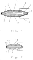
- a pressure sensor of the type shown in FIG. 1 has two lid-shaped steel disks 1, 2, which form a gap to one another in the membrane area by means of a lid-shaped profiling.
- the steel disks lie directly on top of one another in the edge region and are connected to one another on their outside by a weld seam 3 generated by means of a laser beam.
- the welding is carried out in particular on rotary welding systems. It has the advantage that the heating of the steel disks only occurs selectively and for a very short time, so that almost no interior heating occurs during welding. Due to the solder-free welding, the steel disks can also lie directly on top of each other. The weld is extremely strong and the entire load cell formed from the steel disks can therefore be used even under high pressures.
- the two steel disks have annular thickness weakenings 7, 8 in their outer membrane area, which enable the membrane surfaces to be deflected better.
- the steel disks are provided with piezo crystals 4, 5 which are glued to the outer surface of the steel disks in their membrane area. If it is desired to glue the piezocrystals in isolation from the steel disks, an insulating adhesive must be used. However, it is preferred to use a conductive adhesive, the conductivity of which is generated by adding silver powder to the adhesive, so that the poles of the piezo crystals directed against the steel disks have direct electrical contact with the steel disks.
- the outer surfaces of the piezo crystals are provided with connecting wires.
- This construction of the pressure sensor means that the piezo disks are switched in the opposite direction so that acceleration signals that act on both piezo sensors in the same direction cancel each other out.
- a prerequisite for this is the complete symmetry of the structure of the pressure sensor.
- the entire pressure sensor is then coated with a highly insulating synthetic resin coating, which preferably also includes the insulation of the connecting lines 9, 10. As a result, all areas of the pressure sensor are electrically isolated from the environment.
- UV radiation is used for curing. This avoids the formation of a gradient in the curing process and thus a possible non-uniformity in the coating.
- Urethane methyl acrylate or acrylic ester is preferably used.
- the deflection of the membranes depends on the depth of use under water.
- the distance between the membranes of the steel disks 1, 2 is preferably set such that the membrane inner surfaces touch one another from a water depth of about 30 m, so that at greater depths no more measurement signal can be removed from the piezo receivers, since there is no longer any deflection of the membranes is detectable.
- the inner distance between the membranes is about 0.3 to 0.4 mm.
- the thickness of the piezo disks is approximately 0.2 mm.
- FIG. 2 shows an alternative embodiment of a pressure sensor.
- Two flat steel disks 11, 12 are used, which are held on the edge side by a spacer ring 15 at a distance of approximately 0.5 mm.
- a profiling of the steel disks 11, 12 can be used in a manner similar to that in the embodiment in FIG. 1.
- Piezo crystals 13, 14 are glued to the top of the steel disks.
- the steel disks 11, 12 are welded to the spacer ring 15 via two circumferential weld seams.
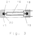
- FIG. 3 shows a pressure sensor according to FIG. 1, which is inserted into an annular holder 17.
- the holder has an annular inner groove 20 in which there is an elastic ring, in particular rubber ring 21, which receives the edge of the pressure sensor 16.
- connecting lines 18, 19 are connected, which are passed through the holder 17, which also has the function of strain relief.
- the hydrophones manufactured in this way are attached along a streamer at equidistant intervals and connected in groups.
- the profiles 7, 8 can be embossed during the deep-drawing of the steel disks, but machining can also be used. In cases in which the acceleration components cannot be compensated for, it can be provided that the symmetry of the pressure sensor is dispensed with and that only one disk is used as a membrane with a piezo crystal.
Claims (7)
- Hydrophone destiné en particulier à être utilisé dans une flûte sismique marine, comportant un détecteur de pression sur les surfaces formant membranes duquel sont fixés des détecteurs piézoélectriques (4, 5), étant précisé que le détecteur de pression se compose de deux plaques métalliques (1, 2) globalement en forme de disques et espacées à l'opposé l'une de l'autre dans la zone centrale, qui sont reliées sur leur bord de façon étanche au gaz, et qu'un détecteur piézoélectrique (4, 5) est fixé sur la face extérieure de chaque plaque métallique (1, 2), le détecteur de pression étant isolé électriquement par rapport à son environnement extérieur, caractérisé en ce que les plaques métalliques (1, 2) ont un profilage en forme de couvercle avec une zone de bord et, en retrait, une zone formant membrane globalement plane, en ce que les plaques métalliques (1, 2) sont reliées par une soudure au laser (3) réalisée sur le bord, et en ce que l'ensemble du détecteur de pression, y compris les détecteurs piézoélectriques et les lignes de raccordement, est recouvert d'une couche de matière synthétique (6) électriquement isolante.
- Hydrophone selon la revendication 1, caractérisé en ce qu'il est prévu, au bord de la zone formant membrane, un autre profilage annulaire (8) présentant une réduction partielle de l'épaisseur de membrane.
- Hydrophone selon la revendication 1, caractérisé en ce que les détecteurs piézoélectriques (4, 5) sont collés sur les plaques métalliques (1, 2) grâce à une couche adhésive conductrice, la conductivité de la couche adhésive étant obtenue grâce à l'adjonction de poudre d'argent à l'agent adhésif.
- Hydrophone selon la revendication 1, caractérisé en ce que la couche de matière synthétique est apte à être durcie par rayonnement UV.
- Hydrophone selon la revendication 4, caractérisé en ce que la couche de matière synthétique est constituée de méthylacrylate d'uréthanne ou d'ester acrylique.
- Hydrophone selon l'une au moins des revendications précédentes, caractérisé en ce que le détecteur de pression est logé dans un support annulaire (17) et plusieurs hydrophones sont placés, espacés les uns des autres, dans une flûte sismique marine.
- Procédé pour fabriquer un hydrophone selon l'une au moins des revendications précédentes, comprenant les phases suivantes : dans deux plaques métalliques planes (1, 2), on réalise par estampage une zone de bord en relief ; on relie les plaques estampées par soudage au laser dans les zones du bord qui se touchent ; on colle des détecteurs piézoélectriques sur la zone centrale des plaques métalliques ; et on scelle électriquement les plaques métalliques, y compris les détecteurs piézoélectriques et les éléments de raccordement électriques, à l'aide d'une couche de matière synthétique apte à être durcie par UV.
Applications Claiming Priority (2)
| Application Number | Priority Date | Filing Date | Title |
|---|---|---|---|
| DE4226485A DE4226485C1 (de) | 1992-08-11 | 1992-08-11 | Hydrophon, Verfahren zu seiner Herstellung und Verwendung |
| DE4226485 | 1992-08-11 |
Publications (3)
| Publication Number | Publication Date |
|---|---|
| EP0586828A2 EP0586828A2 (fr) | 1994-03-16 |
| EP0586828A3 EP0586828A3 (fr) | 1995-01-18 |
| EP0586828B1 true EP0586828B1 (fr) | 1997-03-05 |
Family
ID=6465258
Family Applications (1)
| Application Number | Title | Priority Date | Filing Date |
|---|---|---|---|
| EP93111073A Expired - Lifetime EP0586828B1 (fr) | 1992-08-11 | 1993-07-10 | Hydrophone |
Country Status (7)
| Country | Link |
|---|---|
| US (1) | US5394379A (fr) |
| EP (1) | EP0586828B1 (fr) |
| AU (1) | AU4458093A (fr) |
| CA (1) | CA2103598A1 (fr) |
| DE (2) | DE4226485C1 (fr) |
| ES (1) | ES2102556T3 (fr) |
| NO (1) | NO932840L (fr) |
Families Citing this family (17)
| Publication number | Priority date | Publication date | Assignee | Title |
|---|---|---|---|---|
| US5815466A (en) * | 1995-12-27 | 1998-09-29 | Syntron, Inc. | Hydrophone structure with reverse bend of piezoelectric element |
| US5677894A (en) * | 1995-12-27 | 1997-10-14 | Syntron Inc. | Hydrophone structure with center pin |
| FR2748183B1 (fr) * | 1996-04-29 | 1998-05-22 | Inst Francais Du Petrole | Hydrophone et procede pour sa fabrication |
| US6049511A (en) * | 1999-05-07 | 2000-04-11 | Geosensor Corporation | High sensitivity fiber optic hydrophone |
| US6498769B1 (en) | 2000-08-04 | 2002-12-24 | Input/Output, Inc. | Method and apparatus for a non-oil-filled towed array with a novel hydrophone design and uniform buoyancy technique |
| GB0020072D0 (en) | 2000-08-16 | 2000-10-04 | Geco As | A housing for a seismic sensing element and a seismic sensor |
| CA2426823A1 (fr) * | 2000-10-25 | 2002-10-24 | Washington State University Research Foundation | Microtransducteurs piezo-electriques, procedes d'utilisation et procedes de fabrication correspondants |
| US6571598B2 (en) * | 2001-08-13 | 2003-06-03 | The United States Of America As Represented By The Secretary Of The Navy | Calibration circuit for use with a differential input preamplifier in a sensor system |
| US7029488B2 (en) * | 2001-08-22 | 2006-04-18 | Gore Enterprise Holdings, Inc. | Mechanical thrombectomy device for use in cerebral vessels |
| FR2853968B1 (fr) * | 2003-04-17 | 2005-06-24 | Geophysique Cie Gle | Dispositif et procede de mesure d'ondes sismiques |
| US7573781B2 (en) * | 2004-07-30 | 2009-08-11 | Teledyne Technologies Incorporation | Streamer cable with enhanced properties |
| DE202005011044U1 (de) * | 2005-07-06 | 2006-11-16 | Brose Fahrzeugteile Gmbh & Co. Kommanditgesellschaft, Coburg | Sensorsystem für eine Einklemmschutzvorrichtung |
| US20080191584A1 (en) * | 2007-02-08 | 2008-08-14 | Malkin Matthew C | Spring disc energy harvester apparatus and method |
| US8415860B2 (en) * | 2007-02-08 | 2013-04-09 | The Boeing Company | Spring disc energy harvester apparatus and method |
| US9321630B2 (en) | 2013-02-20 | 2016-04-26 | Pgs Geophysical As | Sensor with vacuum-sealed cavity |
| PL3276313T3 (pl) * | 2016-07-26 | 2021-02-08 | Kistler Holding Ag | Czujnik WIM z pakietem czujnika |
| CN111337117B (zh) * | 2020-04-14 | 2022-07-05 | 青岛海洋科学与技术国家实验室发展中心 | 一种光纤激光水听器 |
Family Cites Families (12)
| Publication number | Priority date | Publication date | Assignee | Title |
|---|---|---|---|---|
| US3360664A (en) * | 1964-10-30 | 1967-12-26 | Gen Dynamics Corp | Electromechanical apparatus |
| FR2122675A5 (fr) * | 1971-01-19 | 1972-09-01 | Inst Francais Du Petrole | |
| GB1435125A (en) * | 1972-05-22 | 1976-05-12 | Texas Instruments Inc | Seismic cable |
| US3832762A (en) * | 1972-05-22 | 1974-09-03 | Texas Instruments Inc | Method of producing a matched parameter acceleration cancelling hydrophone |
| US5003285A (en) * | 1972-09-08 | 1991-03-26 | The United States Of America As Represented By The Secretary Of The Navy | Transducer array |
| US3970878A (en) * | 1975-03-31 | 1976-07-20 | Teledyne Exploration Company | Piezoelectric transducer unit and hydrophone assembly |
| DE2941028A1 (de) * | 1979-10-10 | 1981-04-23 | Honeywell Inc., Minneapolis, Minn. | Hydrophon-schleppkoerper |
| US4639283A (en) * | 1983-12-02 | 1987-01-27 | Nippon Gakki Seizo Kabushiki Kaisha | Method for making a diaphragm for an electro-acoustic transducer |
| NO155599C (no) * | 1984-09-19 | 1987-04-22 | Norway Geophysical Co | Anordning ved hydrofon. |
| NO160959C (no) * | 1986-09-26 | 1991-01-29 | Geco As | Piezoelektrisk hydrofon. |
| US4709361A (en) * | 1986-10-30 | 1987-11-24 | Allied Corporation | Flexural disk transducer |
| DE3931578A1 (de) * | 1989-09-22 | 1991-04-04 | Wolf Gmbh Richard | Piezoelektrisches membran-hydrophon |
-
1992
- 1992-08-11 DE DE4226485A patent/DE4226485C1/de not_active Expired - Fee Related
-
1993
- 1993-07-10 EP EP93111073A patent/EP0586828B1/fr not_active Expired - Lifetime
- 1993-07-10 DE DE59305576T patent/DE59305576D1/de not_active Expired - Fee Related
- 1993-07-10 ES ES93111073T patent/ES2102556T3/es not_active Expired - Lifetime
- 1993-08-04 US US08/101,975 patent/US5394379A/en not_active Expired - Fee Related
- 1993-08-09 CA CA002103598A patent/CA2103598A1/fr not_active Abandoned
- 1993-08-10 NO NO932840A patent/NO932840L/no unknown
- 1993-08-11 AU AU44580/93A patent/AU4458093A/en not_active Abandoned
Also Published As
| Publication number | Publication date |
|---|---|
| AU4458093A (en) | 1994-02-17 |
| DE59305576D1 (de) | 1997-04-10 |
| US5394379A (en) | 1995-02-28 |
| EP0586828A3 (fr) | 1995-01-18 |
| CA2103598A1 (fr) | 1994-02-12 |
| NO932840D0 (no) | 1993-08-10 |
| DE4226485C1 (de) | 1993-12-23 |
| EP0586828A2 (fr) | 1994-03-16 |
| ES2102556T3 (es) | 1997-08-01 |
| NO932840L (no) | 1994-02-14 |
Similar Documents
| Publication | Publication Date | Title |
|---|---|---|
| EP0586828B1 (fr) | Hydrophone | |
| DE2832762C2 (de) | Schwingungs- und Beschleunigungsaufnehmer | |
| DE2831938C2 (fr) | ||
| EP0178346B1 (fr) | Transducteur à ultrasons | |
| DE2820478A1 (de) | Kapazitiver druckfuehlerwandler und verfahren zu seiner herstellung | |
| DE2906407C2 (de) | Piezoelektrisches Wandlerelement zum Einbau in Druck-, Kraft- oder Beschleunigungsaufnehmer | |
| EP0654953A1 (fr) | Arrangement des transducteurs électroacoustiques | |
| DE2202290C2 (de) | Druckwandler zum Umwandeln von Flüssigkeitsdrucksignalen in elektrische Signale | |
| DE3423193C2 (fr) | ||
| DE3532615A1 (de) | Anordnung in einem hydrophon | |
| DE3032221A1 (de) | Schallwandler | |
| EP0436809A2 (fr) | Sonde ultrasonore comportant des éléments piézoélectriques | |
| EP0193886A2 (fr) | Membrane pour haut-parleur plan | |
| DE102008012591B4 (de) | Koaxialleitung mit Stützscheiben | |
| DE2326064A1 (de) | Seismische trosse | |
| DE1447995A1 (de) | Elektromechanischer Wandler | |
| EP0472085B1 (fr) | Capteur d'ultrason | |
| EP0548470B1 (fr) | Capteur de pression avec un diaphragme en matériau sémi-conducteur | |
| WO2001022039A2 (fr) | Dispositif pour mesurer la densite specifique d'un milieu gazeux ou liquide | |
| DE19717903A1 (de) | Hydrophon und Verfahren zu seiner Herstellung | |
| EP0036187A1 (fr) | Ensemble de support de têtes magnétiques pour magnétoscope | |
| DE3820878C2 (fr) | ||
| DE3149148C2 (de) | Verfahren zur Herstellung einer Kompensationsfilteranordnung für einen Strahlungsdetektor zum Messen einer ionisierenden Strahlung | |
| DE3146986A1 (de) | "elektromechanischer wandler" | |
| DE3821693A1 (de) | Kapazitiver druckwandler und verfahren zur herstellung dieses druckwandlers |
Legal Events
| Date | Code | Title | Description |
|---|---|---|---|
| PUAI | Public reference made under article 153(3) epc to a published international application that has entered the european phase |
Free format text: ORIGINAL CODE: 0009012 |
|
| AK | Designated contracting states |
Kind code of ref document: A2 Designated state(s): AT BE CH DE DK ES FR GB GR IT LI LU MC NL PT SE |
|
| RBV | Designated contracting states (corrected) |
Designated state(s): DE ES FR GB GR IT NL |
|
| PUAL | Search report despatched |
Free format text: ORIGINAL CODE: 0009013 |
|
| AK | Designated contracting states |
Kind code of ref document: A3 Designated state(s): AT BE CH DE DK ES FR GB GR IT LI LU MC NL PT SE |
|
| 17P | Request for examination filed |
Effective date: 19950717 |
|
| GRAG | Despatch of communication of intention to grant |
Free format text: ORIGINAL CODE: EPIDOS AGRA |
|
| 17Q | First examination report despatched |
Effective date: 19960426 |
|
| GRAH | Despatch of communication of intention to grant a patent |
Free format text: ORIGINAL CODE: EPIDOS IGRA |
|
| GRAH | Despatch of communication of intention to grant a patent |
Free format text: ORIGINAL CODE: EPIDOS IGRA |
|
| GRAA | (expected) grant |
Free format text: ORIGINAL CODE: 0009210 |
|
| AK | Designated contracting states |
Kind code of ref document: B1 Designated state(s): DE ES FR GB GR IT NL |
|
| PG25 | Lapsed in a contracting state [announced via postgrant information from national office to epo] |
Ref country code: GR Free format text: LAPSE BECAUSE OF FAILURE TO SUBMIT A TRANSLATION OF THE DESCRIPTION OR TO PAY THE FEE WITHIN THE PRESCRIBED TIME-LIMIT Effective date: 19970305 |
|
| GBT | Gb: translation of ep patent filed (gb section 77(6)(a)/1977) |
Effective date: 19970305 |
|
| REF | Corresponds to: |
Ref document number: 59305576 Country of ref document: DE Date of ref document: 19970410 |
|
| ET | Fr: translation filed | ||
| ITF | It: translation for a ep patent filed |
Owner name: MODIANO & ASSOCIATI S.R.L. |
|
| REG | Reference to a national code |
Ref country code: ES Ref legal event code: FG2A Ref document number: 2102556 Country of ref document: ES Kind code of ref document: T3 |
|
| PLBE | No opposition filed within time limit |
Free format text: ORIGINAL CODE: 0009261 |
|
| STAA | Information on the status of an ep patent application or granted ep patent |
Free format text: STATUS: NO OPPOSITION FILED WITHIN TIME LIMIT |
|
| 26N | No opposition filed | ||
| PGFP | Annual fee paid to national office [announced via postgrant information from national office to epo] |
Ref country code: GB Payment date: 19980708 Year of fee payment: 6 |
|
| PGFP | Annual fee paid to national office [announced via postgrant information from national office to epo] |
Ref country code: ES Payment date: 19980713 Year of fee payment: 6 |
|
| PGFP | Annual fee paid to national office [announced via postgrant information from national office to epo] |
Ref country code: NL Payment date: 19980724 Year of fee payment: 6 |
|
| PGFP | Annual fee paid to national office [announced via postgrant information from national office to epo] |
Ref country code: FR Payment date: 19980729 Year of fee payment: 6 |
|
| PGFP | Annual fee paid to national office [announced via postgrant information from national office to epo] |
Ref country code: DE Payment date: 19980824 Year of fee payment: 6 |
|
| PG25 | Lapsed in a contracting state [announced via postgrant information from national office to epo] |
Ref country code: GB Free format text: LAPSE BECAUSE OF NON-PAYMENT OF DUE FEES Effective date: 19990710 |
|
| PG25 | Lapsed in a contracting state [announced via postgrant information from national office to epo] |
Ref country code: ES Free format text: LAPSE BECAUSE OF NON-PAYMENT OF DUE FEES Effective date: 19990711 |
|
| PG25 | Lapsed in a contracting state [announced via postgrant information from national office to epo] |
Ref country code: FR Free format text: THE PATENT HAS BEEN ANNULLED BY A DECISION OF A NATIONAL AUTHORITY Effective date: 19990731 |
|
| PG25 | Lapsed in a contracting state [announced via postgrant information from national office to epo] |
Ref country code: NL Free format text: LAPSE BECAUSE OF NON-PAYMENT OF DUE FEES Effective date: 20000201 |
|
| GBPC | Gb: european patent ceased through non-payment of renewal fee |
Effective date: 19990710 |
|
| NLV4 | Nl: lapsed or anulled due to non-payment of the annual fee |
Effective date: 20000201 |
|
| PG25 | Lapsed in a contracting state [announced via postgrant information from national office to epo] |
Ref country code: DE Free format text: LAPSE BECAUSE OF NON-PAYMENT OF DUE FEES Effective date: 20000503 |
|
| REG | Reference to a national code |
Ref country code: FR Ref legal event code: ST |
|
| REG | Reference to a national code |
Ref country code: ES Ref legal event code: FD2A Effective date: 20000810 |
|
| PG25 | Lapsed in a contracting state [announced via postgrant information from national office to epo] |
Ref country code: IT Free format text: LAPSE BECAUSE OF NON-PAYMENT OF DUE FEES Effective date: 20050710 |