EP0585408B1 - Zahnbürste mit schaukelbewegung - Google Patents
Zahnbürste mit schaukelbewegung Download PDFInfo
- Publication number
- EP0585408B1 EP0585408B1 EP92916741A EP92916741A EP0585408B1 EP 0585408 B1 EP0585408 B1 EP 0585408B1 EP 92916741 A EP92916741 A EP 92916741A EP 92916741 A EP92916741 A EP 92916741A EP 0585408 B1 EP0585408 B1 EP 0585408B1
- Authority
- EP
- European Patent Office
- Prior art keywords
- bristle support
- toothbrush
- handle
- pad
- distal end
- Prior art date
- Legal status (The legal status is an assumption and is not a legal conclusion. Google has not performed a legal analysis and makes no representation as to the accuracy of the status listed.)
- Expired - Lifetime
Links
Images




Classifications
-
- A—HUMAN NECESSITIES
- A46—BRUSHWARE
- A46B—BRUSHES
- A46B5/00—Brush bodies; Handles integral with brushware
- A46B5/002—Brush bodies; Handles integral with brushware having articulations, joints or flexible portions
- A46B5/0025—Brushes with elastically deformable heads that change shape during use
-
- A—HUMAN NECESSITIES
- A46—BRUSHWARE
- A46B—BRUSHES
- A46B7/00—Bristle carriers arranged in the brush body
- A46B7/06—Bristle carriers arranged in the brush body movably during use, i.e. the normal brushing action causing movement
-
- A—HUMAN NECESSITIES
- A46—BRUSHWARE
- A46B—BRUSHES
- A46B2200/00—Brushes characterized by their functions, uses or applications
- A46B2200/10—For human or animal care
- A46B2200/1066—Toothbrush for cleaning the teeth or dentures
-
- Y—GENERAL TAGGING OF NEW TECHNOLOGICAL DEVELOPMENTS; GENERAL TAGGING OF CROSS-SECTIONAL TECHNOLOGIES SPANNING OVER SEVERAL SECTIONS OF THE IPC; TECHNICAL SUBJECTS COVERED BY FORMER USPC CROSS-REFERENCE ART COLLECTIONS [XRACs] AND DIGESTS
- Y10—TECHNICAL SUBJECTS COVERED BY FORMER USPC
- Y10T—TECHNICAL SUBJECTS COVERED BY FORMER US CLASSIFICATION
- Y10T403/00—Joints and connections
- Y10T403/54—Flexible member is joint component
Definitions
- the present invention is in the field of toothbrushes, particularly toothbrushes devised to impart an up-down motion as the brush is stroked side-to-side along a user's teeth.
- toothbrushes have in common an elongate member with a handle to be grasped by the user and bristles positioned at one end for brushing against the teeth.
- elongate members with straight handles and some have employed members with angled handles.
- DE-A-1805982 discloses a toothbrush having a head and a handle.
- the head is slidable along a path with respect to the handle.
- the path is non-parallel to the longitudinal axis of the handle.
- the friction between the teeth and the head of the toothbrush causes the head to repeatedly slide from end to end of the non-parallel path. This enables the user to brush in a conventional side to side manner whilst the head simultaneously executes and up and down motion.
- the present invention seeks to resolve the problem as noted above and to provide other improvements.
- One embodiment comprises a brush having an elongate handle with means at the distal end devised to hold the bristles.
- the bristles are affixed in separate bristle-holding elongate pads which are configured to as to be pivotally attached to cooperating pad-holding mean.
- the bristles are affixed in bristle-holding elongate pads which are integral with and configured so as to be hingedly attached to the pad-holding distal end of the toothbrush.
- each pad is of elongate configuration devised so as to secure, preferably, two elongate rows of bristles.
- the bristles are of conventional design as found in other toothbrushes.
- the pads are so sized and configured as to permit a pair of pads to be preferably positioned in a side-by-side relationship with a relatively small space between, for reasons explained below.
- a second similar pair of pads is preferably positioned in an end-to-end relationship to the first pair with a relatively small space between.
- the entire assembly of four pads is so sized and configured as to occupy approximately the same area at the distal end of the toothbrush as do the bristles in conventional toothbrushes.
- each pad is pivotally attached to the pad-holding distal end of the toothbrush.
- the pivotal attachment comprises, preferably, an elongate pivot hinge, positioned so as to have the pivotal axis form an acute angle with respect to the elongate axis of the pad.
- the pivotal axis of a pair of pads are preferably so arranged as to form a substantially "V" configuration.
- adjacent pads have a space between them, and therefore the apex at the "V" is open, i.e., the legs of the "V” do not come completely together.
- each pad is hingedly attached to the pad-holding distal end of the toothbrush.
- the hinged attachment comprises, preferably, an elongate web, interconnecting the pad to the distal end of the toothbrush, and positioned so as to have the hinge axis form an acute angle with respect to the elongate axis of the pad.
- the hinge axes of a pair of pads are preferably so arranged as to form a substantially "V" configuration.
- adjacent pads have a space between them, and therefore the apex at the "V" is open, i.e., the legs of the "V" do not come completely together.
- each pair of pads is, preferably, so arranged that the corresponding open apexes of the "V"s are adjacent to each other although there is a space between, as noted above.
- the pairs could be so arranged that the mouths of the "V"s were adjacent each other.
- the pivot hinge comprises, preferably, a rod-like member which is an integral part of the pad and is positioned at the bottom of the pad, and an elongate receiving receptor which is an integral part of the pad-holding end of the brush.
- the rod-like member comprises a rod having a truncated circular cross-section and also having an elongate protruding web which serves to connect the rod-like member to the bottom of the pad.
- the truncated circular segment of the perimeter comprises somewhat more than a semi-circle.
- the protruding web is configured with a relatively short, but preferred, connecting dimension, as to be described in more details below.
- the receiving receptor is fashioned as a groove in the pad-holding end of the brush, and likewise has a truncated circular cross section which comprises somewhat more than a semi-circle.
- the radius of the circular segment of the receiving receptor is slightly greater than the radius of the circular segment of the rod-like member, being so sized that when the rod-like member is engaged with the receiving receptor it fits snugly, but not tightly, therein, thus allowing it to pivot freely, but not loosely.
- the bristle-holding pad rocks back and forth. The importance of the connecting dimension of the protruding web on the rod-like member now becomes apparent.
- This dimension must be such as to permit the base of the pad to be spaced above the pad-holding end of the brush so as to allow the pad to rock a preferred amount before it strikes the pad-holding end. At the same time this dimension must not be too great or the pad would rock too far.
- the configuration will be such that the pad can rock back and forth through an angle of approximately ⁇ 45°.
- the reason for the spacing between adjacent pads also now becomes apparent.
- the spacing is preferably such that as adjacent pads rock oppositely so as to bring the bristles towards each other the bristles impact each other but do not significantly intermesh. Furthermore, the pads rock without mutual interference.
- the integral hinge comprises, preferably, a relatively thin elongate web which is an integral part of the distal end of the toothbrush and is positioned so as to interconnect the bottom of the pad to the pad-holding distal end of the brush.
- the web comprises a substantially hour-glass shaped cross-section which, as indicated, serves to connect the bottom of the pad to the distal end of the brush.
- the web is configured with a relatively short, but preferred, connecting dimension, as to be described in more detail below.
- the bristle-holding pad rocks back and forth.
- This dimension must be such as to permit the base of the pad to be spaced above the pad-holding end of the brush so as to allow the pad to rock a preferred amount before it strikes the pad-holding end. At the same time this dimension must not be too great or the pad would rock too far.
- the configuration will be such that the pad can rock back and forth through an angle of approximately 45°.
- the invention also comprises an alternate embodiment of the pivotal engagement means.
- a pair of knobs are employed rather than a rod-like member, and a pair of knob-receiving receptors ar employed rather than an elongate receiving receptor.
- the pair of knobs protrude from opposite ends of the pad and are positioned along the pivotal axis of the pad.
- the knob-receiving receptors are emplaced and configured so as to snugly, but not tightly, engage and secure therein the pair of knobs when emplaced therein.
- each pad has its pivotal axis arranged to be at an acute angle with respect to the elongate longitudinal axis of the pad.
- the pads move back and forth in a longitudinal direction.
- the pair of pads which has the apex of its "V" shape facing the direction of motion will rock transverse to the direction of motion, outwardly and oppositely to each other, thus spacing their bristles farther apart.
- the pads, webs and body of the toothbrush are preferably molded from a plastic which is sufficiently strong, but yet somewhat elastic, such that the rod-like members can be snapped into position in the receptors, at least when still warm after being removed from the molds.
- the web hinges preferably assume a neutral position when not being activated.
- drain holes are preferably provided through the body of the brush which communicate at one end with the pivotal engagement means or web hinges and at the other end with open space.
- the pivot or brush can be washed and kept free of debris.
- a still further embodiment of the invention employs means whereby the pads incorporate slide members which engage sideways, thus providing a sliding up-down motion of the bristles rather than a rocking up-down motion.
- a pair of transverse elongate rod-like members are incorporated respectively at opposite ends of each pad.
- These slide members protrude from the pad and are positioned such that their axes form an acute angle with the elongate axis of the pad, the angle being somewhat less than 90°.
- These slide members comprise rods having a truncated circular cross-section, and also having an elongate protruding web which serves to connect the rod to the bottom of the pad.
- the truncated circular segment of the perimeter comprises somewhat more than a semi-circle.
- the protruding web is configured with a relatively short connecting dimension servicing to connect the slide member to the pad and to space it slightly therefrom.
- the receiving receptor is fashioned as a groove in the pad-holding end of the brush, and likewise has a truncated circular cross section which comprises somewhat more than a semi-circle.
- the radius of the circular segment of the receiving receptor is slightly greater than the radius of the circular segment of the slide member, being so sized that when the slide member is engaged with the receiving receptor it fits snugly, but not tightly, therein, thus allowing it to slide freely, but not loosely.
- the bristle-holding pad slides back and forth.
- pads there are preferably two pairs of pads per toothbrush. These pads, in the illustrated embodiment, are configured and emplaced such that the slideway axes of a pair of pads form a substantially "V" configuration, with a slight space between them such that the apex of the "V” is open.
- the two pairs of pads are so emplaced that one pair is end-to-end adjacent to the other pair, and such that either the apexes of the "V"s, or, alternatively, the mouths of the "V”s are adjacent each other.
- transverse motion axis being the axis along which, or about which, a transverse motion of a pad takes place as the brush is stroked along the elongate axis of the pad.
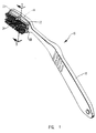
- the toothbrush 10 is shown having a conventional elongate handle 12 and a bristle pad-holding end 14 configured in conformity with the present invention. As shown in Figures 1 and 2, there are preferably four bristle-holding pads, 20, 22, 24, and 26, which engage the pad-holding end 14. Likewise, as shown, there are preferably two rows of bristles per pad although there may be more or less.
- each pad is devised so as to be pivotally attached to the pad-holding end 14.
- the pivotal attachment for each pad comprises a hinge which in turn comprises a rod-like member, such as 30, affixed to pad 26, and a receiving receptor 32 affixed to pad-holding end 14.
- rod-like members 33, 34, 35 there are receiving receptors 36, 37, 38.
- rod-like member 30 is fashioned as an integral part of pad 26, as shown best in Figure 3.
- receiving receptor 32 is fashioned as an integral part of pad-holding end 14.
- Rod-like member 30 is configured so as to be substantially circular, but truncated, in cross-section having an elongate protruding web 40 extending from a small segment of the perimeter of member 30, such that the circular segment of member 30 comprises somewhat more than a semi-circle.
- Receiving receptor 32 is an elongate groove configured so as to be substantially circular in cross section, but being truncated such that the circular engagement comprises somewhat more than a semi-circle.
- the radius of the circular segment of member 30 is slightly less than the radius of the circular segment of receptor 32.
- the radii are chosen such that member 30 engages receptor 32 snugly, but not tightly.
- member 30 can pivot freely in receptor 32 when a pivotal force is applied to pad-holding end 26, normally by way of the bristles.
- the engagement is snug enough that member 30 does not pivot by itself merely due to gravitational forces.
- Rod-like member 30 is assembled to pad-holding end 14 by being snapped into place.
- member 30 and pad-holding end 14 are fashioned, preferably, from a molded plastic material which has sufficient strength to make the toothbrush substantially rigid, but at the same time has sufficient elasticity that member 30 can be snapped into receptor 32 even though the opening in member 32 is less than the diameter of member 30. It has been found that this snap-fitting can be most easily effected when the parts are still warm as they come from the mold. Once engaged the assembly is substantially permanent.
- a satisfactory material is polycarbonate.
- pad 26 rocks back-and-forth.
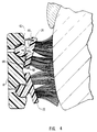
- the angle ⁇ (see Figure 4) through which the pad can rock is determined by the dimensions of protruding web40 and the contour of pad-holding end 14.
- pad-holding end 14 has inclined surfaces 42 and 44 against which surfaces 46 and 48 of pad 26 abut when pad 26 is rocked to its limits. This is shown best in Figures 4 and 5.
- the configuration is such that pad 26 can rock through the angle ⁇ of approximately ⁇ 45°, i.e. 22.5° in each direction, although this angle is not critical. However, it should preferably be within the range of 10° to 90°.
- the spacing "d,” see Figure 3, between adjacent pads 26 and 22 is such that when the pads are rocked towards each other the tips of the bristles impact each other but do not substantially intermesh, as shown in Figure 4.
- the spacing is also such that pads 26 and 22 do not interfere with each other when rocked through their respective maximum angles, as depicted in Figure 4.
- a significant advantage of the toothbrush of this invention is the greater area of a tooth that is covered as the brush is stroked from side-to-side by a user.
- the up-down dimension that is covered by a brush that did not rock is depicted as “k.”
- this dimension for a brush that does rock is depicted as “m.”
- "M" is significantly greater than "k.”
- drain holes such as 50 shown in Figures 2 and 3.
- a plurality of drain holes communicate at one end with the hinge and at the other end with open space, all as shown. These facilitate the cleaning of the brush, especially the hinge, by allowing water to circulate therethrough.
- each pad such as 26 is so positioned that it forms an acute angle " ⁇ " with respect to the elongate axis of the pad.
- the receptor 32 forms a similar angle with respect to the elongate axis of the pad-holding end 14 of the brush.
- Adjacent pads 22 and 26 are positioned such that rod-like members 30 and 33 form substantially a "V" shape with the apex of the "V" in the center of the brush and the mouth of the "V" at the end.
- pads 20 and 24 are similarly positioned, with the apex of the "V” formed by members 34 and 35 adjacent to the apex of the "V” formed by members 30 and 33. Although this is preferred configuration the pads can be so positioned that the mouths of the "V”s are adjacent rather than the apexes of the "V”s.
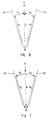
- FIGs 6 and 7 represent, in schematic form, the tips of bristles in pads 22 and 26.
- "a” represents the direction of a force transmitted to these bristle tips with a 1 being its magnitude.
- a 1 is composed of forces a 2 , directed along the elongate axis of the bristles, and a 3 , orthogonal thereto.
- the force a 3 acts at the end of a crank arm of the pivot comprised of rod-like member 30 and receptor 32.
- the crank arm is comprised of a combination of the bristles, the pad 26, and the protruding web 40.
- a 1 is composed of forces a 5 , directed along the elongate axis of the bristles, and a 4 , orthogonal thereto.
- a 4 rotates the tips of the bristles, and thus the pad, inwardly.
- each pad is devised so as to be hingedly attached to the pad-holding end 14a.
- the attachment for each pad comprises a web hinge, such as 30a, affixed to a pad such as 26a.
- a web hinge such as 30a
- a pad such as 26a.
- hinge 30a is fashioned as an integral part of pad 26a and pad-holding end 14a, as shown best in Figure 9.
- hinges 35a, 33a and 34a are fashioned as an integral part of pad-holding end 14a and their corresponding pads.
- Hinge 30a is configured so as to be substantially hour-glass shaped in cross section having an elongate web 40a extending from pad-holding end 14a to pad 26a.
- member 26a can pivot freely when a pivotal force is applied to pad-holding end 26a, normally by way of the bristles.
- the web is stiff enough that member 26a does not pivot by itself merely due to gravitational forces.
- pad 26a rocks back-and-forth.
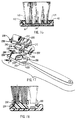
- the angle ⁇ (see Figure 10) through which the pad can rock is determined by the dimensions of web 40a and the contour of pad-holding end 14a.
- pad-holding end 14a has surfaces 42a and 44a against which surfaces 46a and 48a of pad 26a abut when pad 26a is rocked to its limits.
- the configuration is such that pad 26a can rock through an angle of approximately 45°, i.e., 22.5°( ⁇ ) in each direction, although this angle is not critical. However, it should preferably be within the range of 10° to 90°.
- the spacing "d,” see Figure 9, between adjacent pads 26a and 22a is such that when the pads are rocked towards each other the tips of the bristles impact each other but do not substantially intermesh, as shown in Figure 11.
- the spacing is also such that pads 26a and 22a do not interfere with each other when rocked through their respective maximum angles, as depicted in Figure 11.
- a significant advantage of the toothbrush of this invention is the greater area of a tooth that is covered as the brush is stroked from side-to-side by a user.
- the up-down dimension that is covered by a brush that did not rock is depicted as “k.”
- this dimension for a brush that does rock is depicted as “m.”
- "m" is significantly greater than "k.”
- drain holes such as 50a shown in Figures 8, 9, 10 and 11.
- a plurality of drain holes communicate at one end with the space near the hinge and at the other end with open space, all as shown. These facilitate the cleaning of the brush, especially the hinge, by allowing water to circulate therethrough.
- each pad such as 26a
- Adjacent pads 22a and 26a are positioned such that hinges 30a and 33a form substantially a "V" shape with the apex of the "V” in the center of the brush and the mouth of the "V” at the end.
- pads 20a and 24a are similarly positioned, with the apex of the "V” formed by hinges 34a and 35a adjacent to the apex of the "V” formed by hinges 30a and 33a.
- the pads can be so positioned that the mouths of the "V”s are adjacent rather than the apexes of the "V”s.
- 60a and 62a represent, in schematic form, the tips of bristles in pads 22a and 26a.
- "a" represents the direction of a force transmitted to these bristle tips with a 1 being its magnitude.
- a 1 is composed of forces a 2 , directed along the elongate axis of the bristles, and a 3 , orthogonal thereto.
- the force a 3 acts at the end of a crank arm of the hinge.
- the crank arm is comprised of a combination of the bristles, the pad 22a, and the web 33a.
- a 1 is composed of forces a 5 , directed along the elongate axis of the bristles, and a 4 , orthogonal thereto.
- a 4 rotates the tips of the bristles, and thus the pad, inwardly.
- the hinge means comprises a pair of knobs 100 and 102 integral with respective opposite ends of a pad 104. Knobs 100 and 102 protrude outwardly from pad 104 and are positioned so as to lie along a pivotal axis, ⁇ , as shown in Figure 15, wherein the pivotal axis forms an angel ⁇ with respect to the longitudinal axis of the pad within the range of 10° to 90°, preferably being about 45°.
- Pads 110, 112 and 114 have similar respective knobs, not shown, Each knob, such as 128 and 130 shown in Figure 16, is preferably configured as a short round post having a rounded semi-spherical end as shown.
- the pad-holding end 14 of the brush has a turned-up lip 142 fashioned around its perimeter, and also extending across the central region of pad-holding end 14, being orthogonal to the elongate axis of pad-holding end 14.
- Turned-up lip 142 has receptors such as 152, 154, 156, 158, 160, 162, 164, 166, fashioned therein, each of which, such as 152, is configured and emplaced so as to receive and secure a corresponding knob, such as 100, snugly but not nightly.
- Each receptor has a semi-spherical shape, having a radius slightly greater than the radius of a knob.
- Pads 104 and 110 are configured and emplaced such that their pivotal axes form a "V" shape, having an open apex which is adjacent to pads 112 and 114.
- Pads 112 and 114 are configured and emplaced such that their pivotal axes form a "V" shape with the apexes of the "V” being adjacent to the axis of the "V" of pads 104 and 110.
- FIG. 17 A still further embodiment of the invention is shown in Figure 17. This embodiment relies on a sliding action of the pads rather than a rocking action. As before, four pads 200, 202, 204 and 206 are emplaced, pads 200 and 202 being emplaced as an adjacent side-by-side pair, and 204 and 206 emplaced as an adjacent side-by-side pair, also being emplaced in an end-to-end fashion adjacent to pads 200 and 202.
- Each pad such as 200, has a pair of elongate slide members, such as 210 and 212, integral with the bottom of the pad, as shown in Figure 17. These slide members are emplaced near respective opposite ends of the pad, are parallel to each other, and have their axis forming an angle ⁇ within the range of 10° to 90°, preferably about 45°, with respect to the longitudinal axis of the pad.
- Pad-holding end 14 has slideways, such as 220 and 222, fashioned therein, configured and emplaced so as to receive, and secure, corresponding slide members 210 and 212.
- Slideways 220 and 222 are somewhat longer than slide members 210 and 212 so as to allow a controlled amount of sliding motion, as shown best in Figure 18.
- Slide members 210, 212, 230, 232, 234, 236, 238, and 240 are fashioned as rods having a truncated circular cross section comprising somewhat more than a semicircle, and being connected to the bottom of respective pads 200, 202, 204, and 206 by respective webs such as 250 shown in Figure 12.
- Slideways 220, 222, 260, 262, 264, 266, 268 and 270 are fashioned as groves also having a truncated circular cross section comprising somewhat more than a semicircle, and having a radius slightly greater than the radius of the slide members.
- an up-down motion is provided as the brush strokes the teeth in a side-to-side fashion. Further this up-down motion permits the bristles of the brush to penetrate the gum line, and to cover a wider area than would otherwise be possible. Additionally, the combination of the up-down motion and the side-to-side motion effects a brushing of the teeth at all angles, and imparts a swirling motion to the bristles as they cross the teeth. And lastly, this up-down motion is provided without the use of electric vibrators or equivalents.
Landscapes
- Brushes (AREA)
Claims (13)
- Zahnbürste (10) aufweisend einen länglichen Griff (12) mit einem nahen Ende und einem entfernten Ende, die zwischen sich eine Längsachse des Griffes festlegen, wobei die Zahnbürste (10) umfaßt:(a) einen Borstenträger mit einander gegenüberliegenden oberen und unteren Flächen,(b) Borsten, die von der oberen Fläche des Borstenträgers (20, 20a, 104) vorstehen, und(c) eine Borstenträger-Befestigungseinrichtung zum Befestigen des Borstenträgers an dem entfernten Ende des Griffes (12), wobei die Borsten von dem Griff (12) wegragen,
dadurch gekennzeichnet,
daß die Borstenträger-Befestigungseinrichtung (35, 35a, 37, 100, 102) den Borstenträger (20, 20a, 104) für eine Schwenkbewegung der Borsten nur in eine der einander gegenüberliegenden Richtungen um eine Schwenkachse (16) schwenkbar befestigt, die in einem spitzen Winkel zur Längsachse des Griffes (12) angeordnet ist, wobei die Schwenkachse mit der Borstenträger-Befestigungseinrichtung (35, 35a, 100, 102) ausgerichtet ist. - Zahnbürste (10) gemäß Anspruch 1, wobei die Borstenträger-Befestigungseinrichtung (35, 35a, 100, 102) eine erste Borstenträger-Befestigungseinrichtung umfaßt und wobei die Zahnbürste (10) weiterhin umfaßt:(a) einen zweiten Borstenträger (24, 24a, 114) mit einander gegenüberliegenden oberen und unteren Flächen,(b) Borsten, die von der oberen Fläche des zweiten Borstenträgers (24, 24a, 114) wegragen, und(c) einer zweiten Borstenträger-Befestigungseinrichtung (34, 34a, 164, 166) zum schwenkbaren Befestigen des zweiten Borstenträgers (24, 24a, 114) an dem entfernten Ende des Griffes (12) in der Nähe des ersten Borstenträgers (20, 20a, 104), wobei die Borsten an dem zweiten Borstenträger (24, 24a, 114) weg von dem Griff (12) zur Schwenkbewegung nur in eine der zwei einander gegenüberliegenden Richtungen um eine zweite Schwenkachse wegragen, wobei die zweite Schwenkachse mit der zweiten Borstenträger-Befestigungseinrichtung (34, 34a, 164, 166) ausgerichtet ist und die zweite Schwenkachse in einem spitzen Winkel zur ersten Schwenkachse angeordnet ist.
- Zahnbürste gemäß Anspruch 2, wobei die erste Schwenkachse in einem schiefen Winkel zu der zweiten Schwenkachse angeordnet ist.
- Zahnbürste (10) gemäß einem der Ansprüche 2 oder 3, wobei der zweite Borstenträger (24, 24a, 114) an dem entfernten Ende des Griffes (12) seitlich neben dem ersten Borstenträger (20, 20a, 104) angeordnet ist.
- Zahnbürste (10) gemäß einem der Ansprüche 2 oder 3, wobei der zweite Borstenträger (24, 24a, 114) an dem entfernten Ende des Griffes (12) in longitudinaler Ausrichtung mit dem ersten Borstenträger (20, 20a, 104) befestigt ist.
- Zahnbürste (10) gemäß einem der Ansprüche 1 bis 5, wobei die Borstenträger-Befestigungseinrichtung (35a) ein Drehgelenk (35a) umfaßt, das die untere Fläche des Borstenträgers (20a) mit dem entfernten Ende des Griffes (12) verbindet, wobei das Drehgelenk (35a) mit der Schwenkachse ausgerichtet ist.
- Zahnbürste (10) gemäß Anspruch 6, wobei das Drehgelenk (35a), der Borstenträger (20a) und der Griff (12) aus einem einstückigen Aufbau bestehen.
- Zahnbürste (10) gemäß einem der Ansprüche 6 oder 7, wobei das Drehgelenk (35a) einen länglichen Steg umfaßt, der von dem entfernten Ende des Griffes (12) entlang der Schwenkachse aufragt, wobei der Steg den Borstenträger (20a) in einer beabstandeten Beziehung zum Griff trägt.
- Zahnbürste (10) gemäß einem der Ansprüche 6 bis 8, wobei das Drehgelenk (35a) dergestalt aufgebaut ist, daß es den Borstenträger (20a) in einer vorbestimmten Position relativ zum entfernten Ende des Griffes (12) vorspannt, während es eine Schwenkbewegung des Borstenträgers (20a) aus seiner vorbestimmten Position um die Schwenkachse ermöglicht, wenn die von dem Borstenträger (20a) entfernten Enden der Borsten an einer Oberfläche anliegen und durch einen Benutzer eine Kraft senkrecht zur longitudinalen Achse des Griffes (12) ausgeübt wird.
- Zahnbürste (10) gemäß einem der Ansprüche 1 bis 5, wobei die Borstenträger-Befestigungseinrichtung (35) umfaßt:(a) eine längliche Befestigungsstange (35), die an der unteren Fläche des Borstenträgers (20) in einer beabstandeten Beziehung zu diesem befestigt ist, und(b) einen Schlitz (37) zum Aufnehmen der länglichen Befestigungsstange, der in dem entfernten Ende des Griffes (12) ausgebildet ist und eine longitudinale Achse aufweist, die mit der Schwenkachse der Borstenträger-Befestigungseinrichtung (35) zusammenfällt, wobei der aufnehmende Schlitz (37) eine solche Größe aufweist, daß er die Befestigungsstange (35) für eine Schwenkbewegung der Befestigungsstange (35) und des Borstenträgers (20) aufnehmen und halten kann.
- Zahnbürste (10) gemäß einem der Ansprüche 1 bis 5, wobei die Borstenträger-Befestigungseinrichtung (100, 102) umfaßt:(a) eine erste (100) und eine zweite (102) Befestigungsnoppe, die von einander gegenüberliegenden Enden des Borstenträgers (104) wegragen, und(b) eine erste (152) und eine zweite (154) Befestigungsnoppen-Aufnahmebuchse, die einander gegenüberliegen und in dem entfernten Ende des Griffes (12) in Ausrichtung mit der Schwenkachse der Borstenträger-Befestigungseinrichtung (100, 102) ausgebildet sind, wobei die erste (152) und die zweite (154) Aufnahmebuchse eine solche Größe aufweisen und dergestalt angeordnet sind, daß sie die entsprechende erste (100) und zweite (102) Befestigungsnoppe für eine Schwenkbewegung der ersten (100) und zweiten (102) Befestigungsnoppe und des Borstenträgers (104) empfangen und halten.
- Zahnbürste (10) gemäß Anspruch 11, weiterhin mit einer Borstenträger-Aufnahmeausnehmung, die in dem entfernten Ende des Griffes (12) ausgebildet ist, wobei die Borstenträger-Aufnahmeausnehmung eine solche Größe aufweist, daß sie den Borstenträger (104) aufnehmen kann, und wobei die erste (152) und die zweite (154) Aufnahmebuchse in Wänden gegenüberliegender Enden der Borstenträger-Aufnahmeausnehmung ausgebildet sind.
- Zahnbürste (10) gemäß einem der Ansprüche 1 bis 12, weiterhin mit einer Öffnung (50), die in dem entfernten Ende des Griffes (12) in der Nähe der Borstenträger-Befestigungseinrichtung (35) ausgebildet ist.
Applications Claiming Priority (5)
| Application Number | Priority Date | Filing Date | Title |
|---|---|---|---|
| US67765691A | 1991-03-29 | 1991-03-29 | |
| US677656 | 1991-03-29 | ||
| US07/745,892 US5269038A (en) | 1991-03-29 | 1991-08-16 | Rocker toothbrush |
| US745892 | 1991-08-16 | ||
| PCT/US1992/002937 WO1992017094A1 (en) | 1991-03-29 | 1992-03-30 | Rocker toothbrush |
Publications (3)
| Publication Number | Publication Date |
|---|---|
| EP0585408A1 EP0585408A1 (de) | 1994-03-09 |
| EP0585408A4 EP0585408A4 (en) | 1995-11-08 |
| EP0585408B1 true EP0585408B1 (de) | 1999-01-07 |
Family
ID=27101853
Family Applications (1)
| Application Number | Title | Priority Date | Filing Date |
|---|---|---|---|
| EP92916741A Expired - Lifetime EP0585408B1 (de) | 1991-03-29 | 1992-03-30 | Zahnbürste mit schaukelbewegung |
Country Status (5)
| Country | Link |
|---|---|
| US (1) | US5269038A (de) |
| EP (1) | EP0585408B1 (de) |
| AU (1) | AU2400092A (de) |
| DE (1) | DE69228115D1 (de) |
| WO (1) | WO1992017094A1 (de) |
Cited By (1)
| Publication number | Priority date | Publication date | Assignee | Title |
|---|---|---|---|---|
| KR20160120873A (ko) * | 2015-04-09 | 2016-10-19 | 주식회사 네오비 | 칫솔 |
Families Citing this family (55)
| Publication number | Priority date | Publication date | Assignee | Title |
|---|---|---|---|---|
| JPH09506014A (ja) * | 1993-11-05 | 1997-06-17 | シモンズ、ジェームズ・エイ | 歯ブラシ |
| US5481775A (en) * | 1994-03-22 | 1996-01-09 | Chesebrough-Pond's Usa Co., Division Of Conopco, Inc. | Toothbrush with movable head |
| IL109622A (en) * | 1994-05-11 | 1998-06-15 | Amir Ganei Yehudayehuda And Ad | Toothbrushes |
| US5622502A (en) * | 1994-11-22 | 1997-04-22 | Wilkes; David B. | Tooth brush with helical bristles and method |
| US5471702A (en) * | 1995-01-13 | 1995-12-05 | Chesebrough-Pond's Usa Co., Division Of Conopco, Inc. | Toothbrush with lateral stroke correcting features |
| GB2299264B (en) * | 1995-03-27 | 1999-10-20 | Naresh Gathani | A toothbrush to reduce tooth abrasion and improve efficiency |
| GB9524580D0 (en) * | 1995-12-01 | 1996-01-31 | Unilever Plc | A toothbrush with flexibly mounted bristles |
| TW384214B (en) | 1995-12-29 | 2000-03-11 | Colgate Palmolive Co | Contouring toothbrush head |
| US6996870B2 (en) | 1995-12-29 | 2006-02-14 | Colgate-Palmolive Company | Contouring toothbrush head |
| US6006395A (en) * | 1996-01-12 | 1999-12-28 | 500 Group, Inc. | Cushion brush |
| US6408476B1 (en) | 1996-01-18 | 2002-06-25 | The Procter & Gamble Company | Toothbrush with elastomer filled flexible head |
| GB9606900D0 (en) * | 1996-04-02 | 1996-06-05 | Unilever Plc | Toothbrush |
| EP0888072B1 (de) * | 1996-06-27 | 1999-12-08 | M + C SCHIFFER GmbH | Bürste und verfahren zu deren herstellung |
| US5839149A (en) * | 1996-08-26 | 1998-11-24 | Scheier; Paul A. | Toothbrush with resilient flexible bristle support |
| GB9620092D0 (en) * | 1996-09-26 | 1996-11-13 | Unilever Plc | A brush and method for producing same |
| USD390706S (en) | 1996-10-24 | 1998-02-17 | Colgate-Palmolive Company | Toothbrush |
| GB9703274D0 (en) * | 1997-02-17 | 1997-04-09 | Unilever Plc | A toothbrush with flexibly mounted bristles |
| US5799354A (en) * | 1997-02-27 | 1998-09-01 | Amir; Ehud | Toothbrush |
| US5839148A (en) * | 1997-04-17 | 1998-11-24 | The Procter & Gamble Company | Toothbrush with both stationary and moving tufts |
| US5836036A (en) * | 1997-06-20 | 1998-11-17 | Ivory; Brian | Self cleaning toothbrush |
| US6279189B1 (en) * | 1999-11-22 | 2001-08-28 | Simon Ralph Cassar | Flexible insert with stop limits for brush broom handles |
| US6553604B1 (en) | 2000-03-16 | 2003-04-29 | Gillette Canada Company | Toothbrush |
| US20040128784A1 (en) * | 2000-07-18 | 2004-07-08 | Ramy Weitz | Toothbrush with longitudinal to lateral motion conversion |
| IL144053A0 (en) | 2001-06-28 | 2002-12-01 | Medic Nrg Ltd | Improved toothbrush |
| US7908699B2 (en) | 2001-07-03 | 2011-03-22 | Colgate-Palmolive Company | Oral care implement |
| DE10164336A1 (de) | 2001-12-28 | 2003-07-17 | Trisa Holding Ag Triengen | Zahnbürste und Verfahren zur Herstellung einer solchen Zahnbürste |
| US20030126704A1 (en) * | 2002-01-04 | 2003-07-10 | Kristina Bailey-Teets | Toothbrush with a curve |
| US6742951B2 (en) * | 2002-07-23 | 2004-06-01 | S.C. Johnson & Son, Inc. | Cleaning implement |
| US7841041B2 (en) * | 2002-08-09 | 2010-11-30 | Colgate-Palmolive Company | Oral care implement |
| US8876221B2 (en) | 2002-08-09 | 2014-11-04 | Colgate-Palmolive Company | Oral care implement |
| US7845042B2 (en) | 2002-08-09 | 2010-12-07 | Colgate-Palmolive Company | Oral care implement |
| US20060026784A1 (en) | 2002-08-09 | 2006-02-09 | Colgate-Palmolive Company | Oral care implement |
| US8990996B2 (en) * | 2002-08-09 | 2015-03-31 | Colgate-Palmolive Company | Toothbrush |
| US7721376B2 (en) | 2002-09-20 | 2010-05-25 | Colgate-Palmolive Company | Oral care implement |
| US7614111B2 (en) * | 2002-08-09 | 2009-11-10 | Colgate-Palmolive Company | Oral care implement |
| US8806695B2 (en) | 2002-08-09 | 2014-08-19 | Colgate-Palmolive Company | Oral care implement having flexibly supported cleaning elements extending in opposite directions |
| EP2510830B1 (de) * | 2002-08-09 | 2013-12-25 | Colgate-Palmolive Company | Verfahren zum herstellen einer zahnbürste |
| US6931688B2 (en) | 2002-08-09 | 2005-08-23 | Colgate-Palmolive Company | Toothbrush |
| DE10259723A1 (de) | 2002-12-19 | 2004-07-01 | Trisa Holding Ag | Zahnbürste und Verfahren zu deren Herstellung |
| US20060272112A9 (en) * | 2003-03-14 | 2006-12-07 | The Gillette Company | Toothbrush |
| US20040177462A1 (en) | 2003-03-14 | 2004-09-16 | The Gillette Company | Toothbrush head |
| US7941886B2 (en) | 2003-09-19 | 2011-05-17 | Braun Gmbh | Toothbrushes |
| US8141958B2 (en) * | 2004-03-24 | 2012-03-27 | Trisa Holding Ag | Device for holding the head of a toothbrush |
| PY0626124A (es) * | 2005-09-09 | 2011-04-01 | Colgate Palmolive Co | Cepillo dental |
| US8281448B2 (en) | 2005-10-24 | 2012-10-09 | Colgate-Palmolive Company | Oral care implement having one or more moving sections |
| USD637003S1 (en) * | 2006-05-08 | 2011-05-03 | Colgate-Palmolive Company | Toothbrush |
| USD637400S1 (en) * | 2006-05-08 | 2011-05-10 | Colgate-Palmolive Company | Toothbrush |
| US20070277339A1 (en) * | 2006-05-30 | 2007-12-06 | Barsheshet Michael | Toothbrushing system for specialized cleaning |
| USD598198S1 (en) * | 2007-11-15 | 2009-08-18 | Ranir, Llc | Replacement head for an electric toothbrush |
| US8448287B2 (en) | 2010-10-22 | 2013-05-28 | Mcneil-Ppc, Inc. | Replaceable toothbrush head |
| USD675447S1 (en) | 2010-12-21 | 2013-02-05 | Colgate-Palmolive Company | Oral care implement |
| USD675448S1 (en) | 2010-12-21 | 2013-02-05 | Colgate-Palmolive Company | Oral care implement |
| USD675831S1 (en) | 2010-12-21 | 2013-02-12 | Colgate-Palmolive Company | Oral care implement |
| WO2012121806A2 (en) * | 2011-03-10 | 2012-09-13 | Lavery Terrence J | Razor blade cleaning brush |
| MX2018012073A (es) | 2016-04-20 | 2019-05-22 | Trisa Holding Ag | Producto para cepillar y metodo para su produccion. |
Family Cites Families (34)
| Publication number | Priority date | Publication date | Assignee | Title |
|---|---|---|---|---|
| US1225955A (en) * | 1915-06-03 | 1917-05-15 | John Hickman | Rotary tooth-brush. |
| US1212001A (en) * | 1916-03-01 | 1917-01-09 | Harry T Baxter | Tooth-brush. |
| US1270233A (en) * | 1918-03-02 | 1918-06-18 | Max Stoorman | Rotary tooth-brush. |
| GB141640A (en) * | 1919-12-02 | 1920-04-22 | William Edwards Booth | Improvements in or relating to tooth brushes |
| US1620330A (en) * | 1926-02-24 | 1927-03-08 | Samuel E Douglass | Toothbrush |
| US1968303A (en) * | 1931-10-12 | 1934-07-31 | John F Mcmath | Toothbrush |
| US2122619A (en) * | 1936-09-05 | 1938-07-05 | John F Mcmath | Dental instrument |
| US2172624A (en) * | 1937-08-25 | 1939-09-12 | Gabriel Romani Y Robert | Tooth brush |
| US2220053A (en) * | 1938-12-10 | 1940-10-29 | Ibbie L Pruner | Rotary toothbrush |
| US2263802A (en) * | 1939-05-18 | 1941-11-25 | Grusin Arthur | Toothbrush |
| US2246867A (en) * | 1940-06-22 | 1941-06-24 | Arthur J Thomas | Toothbrush |
| US2655674A (en) * | 1946-09-30 | 1953-10-20 | Donald P Grover | Multiple rotary toothbrush with lip guard |
| US2583886A (en) * | 1947-10-17 | 1952-01-29 | Alvin J Schlegel | Power-driven toothbrush with demountably supported rotary brushes |
| US2582552A (en) * | 1949-05-04 | 1952-01-15 | Frederick J Marco | Brush having bristle cleaning apertures |
| US2691187A (en) * | 1952-01-11 | 1954-10-12 | American Hard Rubber Co | Hinge construction for lid members for refrigerator chests |
| US2935755A (en) * | 1955-10-14 | 1960-05-10 | Leira Alberto Ramon | Tooth-brushes and the like |
| US2882544A (en) * | 1957-10-23 | 1959-04-21 | Puzant H Hadidian | Tooth brush |
| GB989953A (en) * | 1960-09-13 | 1965-04-22 | Bernard Cyzer | Improvements in or relating to toothbrushes |
| US3082457A (en) * | 1961-05-26 | 1963-03-26 | Florio R Lucibello | Self-adapting tufts for brushes |
| DE1210409B (de) * | 1961-09-19 | 1966-02-10 | Herbert Schmidt | Buerste mit maschinell in Umlauf setzbarem endlosem Band als Besteckungstraeger |
| US3152349A (en) * | 1963-07-22 | 1964-10-13 | Du Pont | Toothbrush |
| US3290949A (en) * | 1963-12-18 | 1966-12-13 | Gen Precision Inc | Flexural pivot |
| DE1805982A1 (de) * | 1967-11-03 | 1969-06-04 | Vittorino Rainis | Zahnbuerste |
| US3879791A (en) * | 1973-12-14 | 1975-04-29 | Stuart Isler | Training toothbrush |
| US3978852A (en) * | 1975-04-07 | 1976-09-07 | Annoni Jerry D | Plaque jack toothbrush |
| IT1097220B (it) * | 1978-07-13 | 1985-08-26 | Massetti Alessandro | Struttura di spazzolino da denti |
| US4333199A (en) * | 1980-02-22 | 1982-06-08 | Rosario M Del | Toothbrush |
| US4488328A (en) * | 1983-01-24 | 1984-12-18 | Hyman Richard M | Floating head toothbrush |
| IL71065A (en) * | 1984-02-27 | 1989-09-28 | Marta N Berl | Toothbrush |
| FR2562775B1 (fr) * | 1984-04-13 | 1989-12-22 | Taravel Bernard | Brosse a poils retractables elastiquement, notamment pour le brossage de surfaces de relief complexe telles que les dents |
| US4575894A (en) * | 1984-11-02 | 1986-03-18 | Joy Stevens | Vertical action tooth brush |
| JPS622905A (ja) * | 1985-06-29 | 1987-01-08 | 株式会社 サンギ | 歯ブラシ |
| US4712267A (en) * | 1986-12-04 | 1987-12-15 | Cheng Peter S C | Convertible toothbrush |
| US5121520A (en) * | 1990-07-24 | 1992-06-16 | Inter-X Scientific, Inc. | Twin-headed toothbrush |
-
1991
- 1991-08-16 US US07/745,892 patent/US5269038A/en not_active Expired - Fee Related
-
1992
- 1992-03-30 DE DE69228115T patent/DE69228115D1/de not_active Expired - Lifetime
- 1992-03-30 AU AU24000/92A patent/AU2400092A/en not_active Abandoned
- 1992-03-30 EP EP92916741A patent/EP0585408B1/de not_active Expired - Lifetime
- 1992-03-30 WO PCT/US1992/002937 patent/WO1992017094A1/en not_active Ceased
Cited By (1)
| Publication number | Priority date | Publication date | Assignee | Title |
|---|---|---|---|---|
| KR20160120873A (ko) * | 2015-04-09 | 2016-10-19 | 주식회사 네오비 | 칫솔 |
Also Published As
| Publication number | Publication date |
|---|---|
| WO1992017094A1 (en) | 1992-10-15 |
| US5269038A (en) | 1993-12-14 |
| EP0585408A4 (en) | 1995-11-08 |
| DE69228115D1 (de) | 1999-02-18 |
| EP0585408A1 (de) | 1994-03-09 |
| AU2400092A (en) | 1992-11-02 |
Similar Documents
| Publication | Publication Date | Title |
|---|---|---|
| US5398366A (en) | Rocker toothbrush | |
| US5269038A (en) | Rocker toothbrush | |
| EP0669091B1 (de) | ZAHNBüRSTE UND ELEKTRISCH ANGETRIEBENE ZAHNBüRSTE | |
| CN100398033C (zh) | 牙刷 | |
| JP3392864B2 (ja) | ヘッドにて可撓的に連結したゾーンを有する歯ブラシ | |
| US5884354A (en) | Toothbrush | |
| KR100896361B1 (ko) | 칫솔 | |
| RU2430667C2 (ru) | Зубная щетка (варианты) и способ ее изготовления | |
| CA2298578C (en) | Toothbrush with individual standing bristles | |
| CA2277792A1 (en) | A toothbrush with flexibly mounted bristles | |
| KR19990071809A (ko) | 가요성 장착 칫솔모를 갖는 칫솔 | |
| JPH11503623A (ja) | 歯ブラシ | |
| US20020152563A1 (en) | Toothbrush and electric toothbrush | |
| PL170045B1 (pl) | Szczoteczka do zebów PL | |
| US6094768A (en) | Transversal toothbrush | |
| CZ288851B6 (cs) | Zubní kartáček | |
| JP2004514524A (ja) | 長手方向の剛毛補強措置を施された歯ブラシ | |
| MXPA05001587A (es) | Cepillo de dientes. | |
| CA1289703C (en) | Tooth and sulcus brush | |
| RU2066541C1 (ru) | Зубная щетка | |
| CA1326334C (en) | Toothbrush | |
| CA2618892C (en) | Toothbrush with fixed and movable cleaning elements | |
| RU2113813C1 (ru) | Зубная щетка "кит" | |
| MXPA99007260A (en) | A toothbrush with flexibly mounted bristles | |
| HK1110757A (en) | Toothbrush |
Legal Events
| Date | Code | Title | Description |
|---|---|---|---|
| PUAI | Public reference made under article 153(3) epc to a published international application that has entered the european phase |
Free format text: ORIGINAL CODE: 0009012 |
|
| 17P | Request for examination filed |
Effective date: 19931029 |
|
| AK | Designated contracting states |
Kind code of ref document: A1 Designated state(s): DE ES FR GB IT |
|
| A4 | Supplementary search report drawn up and despatched | ||
| AK | Designated contracting states |
Kind code of ref document: A4 Designated state(s): DE ES FR GB IT |
|
| 17Q | First examination report despatched |
Effective date: 19970305 |
|
| GRAG | Despatch of communication of intention to grant |
Free format text: ORIGINAL CODE: EPIDOS AGRA |
|
| GRAG | Despatch of communication of intention to grant |
Free format text: ORIGINAL CODE: EPIDOS AGRA |
|
| GRAH | Despatch of communication of intention to grant a patent |
Free format text: ORIGINAL CODE: EPIDOS IGRA |
|
| GRAH | Despatch of communication of intention to grant a patent |
Free format text: ORIGINAL CODE: EPIDOS IGRA |
|
| GRAA | (expected) grant |
Free format text: ORIGINAL CODE: 0009210 |
|
| AK | Designated contracting states |
Kind code of ref document: B1 Designated state(s): DE ES FR GB IT |
|
| PG25 | Lapsed in a contracting state [announced via postgrant information from national office to epo] |
Ref country code: IT Free format text: LAPSE BECAUSE OF FAILURE TO SUBMIT A TRANSLATION OF THE DESCRIPTION OR TO PAY THE FEE WITHIN THE PRE;WARNING: LAPSES OF ITALIAN PATENTS WITH EFFECTIVE DATE BEFORE 2007 MAY HAVE OCCURRED AT ANY TIME BEFORE 2007. THE CORRECT EFFECTIVE DATE MAY BE DIFFERENT FROM THE ONE RECORDED.SCRIBED TIME-LIMIT Effective date: 19990107 Ref country code: FR Free format text: LAPSE BECAUSE OF FAILURE TO SUBMIT A TRANSLATION OF THE DESCRIPTION OR TO PAY THE FEE WITHIN THE PRESCRIBED TIME-LIMIT Effective date: 19990107 Ref country code: ES Free format text: THE PATENT HAS BEEN ANNULLED BY A DECISION OF A NATIONAL AUTHORITY Effective date: 19990107 |
|
| REF | Corresponds to: |
Ref document number: 69228115 Country of ref document: DE Date of ref document: 19990218 |
|
| PG25 | Lapsed in a contracting state [announced via postgrant information from national office to epo] |
Ref country code: DE Free format text: LAPSE BECAUSE OF FAILURE TO SUBMIT A TRANSLATION OF THE DESCRIPTION OR TO PAY THE FEE WITHIN THE PRESCRIBED TIME-LIMIT Effective date: 19990408 |
|
| EN | Fr: translation not filed | ||
| PLBE | No opposition filed within time limit |
Free format text: ORIGINAL CODE: 0009261 |
|
| 26N | No opposition filed | ||
| REG | Reference to a national code |
Ref country code: GB Ref legal event code: IF02 |
|
| REG | Reference to a national code |
Ref country code: GB Ref legal event code: 746 Effective date: 20050812 |
|
| PGFP | Annual fee paid to national office [announced via postgrant information from national office to epo] |
Ref country code: GB Payment date: 20050928 Year of fee payment: 14 |
|
| PG25 | Lapsed in a contracting state [announced via postgrant information from national office to epo] |
Ref country code: GB Free format text: LAPSE BECAUSE OF NON-PAYMENT OF DUE FEES Effective date: 20060330 |
|
| GBPC | Gb: european patent ceased through non-payment of renewal fee |
Effective date: 20060330 |