EP0585064B1 - Motorisierte Führung zum Ausfräsen und Sägen von Schiebefenstern - Google Patents
Motorisierte Führung zum Ausfräsen und Sägen von Schiebefenstern Download PDFInfo
- Publication number
- EP0585064B1 EP0585064B1 EP93306592A EP93306592A EP0585064B1 EP 0585064 B1 EP0585064 B1 EP 0585064B1 EP 93306592 A EP93306592 A EP 93306592A EP 93306592 A EP93306592 A EP 93306592A EP 0585064 B1 EP0585064 B1 EP 0585064B1
- Authority
- EP
- European Patent Office
- Prior art keywords
- guide
- sash
- rod
- cutting tool
- members
- Prior art date
- Legal status (The legal status is an assumption and is not a legal conclusion. Google has not performed a legal analysis and makes no representation as to the accuracy of the status listed.)
- Expired - Lifetime
Links
- 239000011521 glass Substances 0.000 abstract description 20
- 241000283973 Oryctolagus cuniculus Species 0.000 abstract description 14
- 239000011324 bead Substances 0.000 abstract description 5
- 238000003780 insertion Methods 0.000 abstract description 3
- 230000037431 insertion Effects 0.000 abstract description 3
- 230000006378 damage Effects 0.000 description 4
- 150000001875 compounds Chemical class 0.000 description 3
- 239000002184 metal Substances 0.000 description 2
- 239000012858 resilient material Substances 0.000 description 2
- 238000009966 trimming Methods 0.000 description 2
- 208000008035 Back Pain Diseases 0.000 description 1
- 208000025940 Back injury Diseases 0.000 description 1
- VYZAMTAEIAYCRO-UHFFFAOYSA-N Chromium Chemical compound [Cr] VYZAMTAEIAYCRO-UHFFFAOYSA-N 0.000 description 1
- 230000005484 gravity Effects 0.000 description 1
- 239000011440 grout Substances 0.000 description 1
- 238000012986 modification Methods 0.000 description 1
- 230000004048 modification Effects 0.000 description 1
- 238000010422 painting Methods 0.000 description 1
- 238000007665 sagging Methods 0.000 description 1
- 210000003813 thumb Anatomy 0.000 description 1
- 239000002023 wood Substances 0.000 description 1
- 230000003245 working effect Effects 0.000 description 1
Images
Classifications
-
- B—PERFORMING OPERATIONS; TRANSPORTING
- B27—WORKING OR PRESERVING WOOD OR SIMILAR MATERIAL; NAILING OR STAPLING MACHINES IN GENERAL
- B27C—PLANING, DRILLING, MILLING, TURNING OR UNIVERSAL MACHINES FOR WOOD OR SIMILAR MATERIAL
- B27C1/00—Machines for producing flat surfaces, e.g. by rotary cutters; Equipment therefor
- B27C1/10—Hand planes equipped with power-driven cutter blocks
-
- B—PERFORMING OPERATIONS; TRANSPORTING
- B23—MACHINE TOOLS; METAL-WORKING NOT OTHERWISE PROVIDED FOR
- B23Q—DETAILS, COMPONENTS, OR ACCESSORIES FOR MACHINE TOOLS, e.g. ARRANGEMENTS FOR COPYING OR CONTROLLING; MACHINE TOOLS IN GENERAL CHARACTERISED BY THE CONSTRUCTION OF PARTICULAR DETAILS OR COMPONENTS; COMBINATIONS OR ASSOCIATIONS OF METAL-WORKING MACHINES, NOT DIRECTED TO A PARTICULAR RESULT
- B23Q1/00—Members which are comprised in the general build-up of a form of machine, particularly relatively large fixed members
- B23Q1/25—Movable or adjustable work or tool supports
- B23Q1/44—Movable or adjustable work or tool supports using particular mechanisms
- B23Q1/56—Movable or adjustable work or tool supports using particular mechanisms with sliding pairs only, the sliding pairs being the first two elements of the mechanism
- B23Q1/60—Movable or adjustable work or tool supports using particular mechanisms with sliding pairs only, the sliding pairs being the first two elements of the mechanism two sliding pairs only, the sliding pairs being the first two elements of the mechanism
- B23Q1/62—Movable or adjustable work or tool supports using particular mechanisms with sliding pairs only, the sliding pairs being the first two elements of the mechanism two sliding pairs only, the sliding pairs being the first two elements of the mechanism with perpendicular axes, e.g. cross-slides
- B23Q1/621—Movable or adjustable work or tool supports using particular mechanisms with sliding pairs only, the sliding pairs being the first two elements of the mechanism two sliding pairs only, the sliding pairs being the first two elements of the mechanism with perpendicular axes, e.g. cross-slides a single sliding pair followed perpendicularly by a single sliding pair
-
- B—PERFORMING OPERATIONS; TRANSPORTING
- B23—MACHINE TOOLS; METAL-WORKING NOT OTHERWISE PROVIDED FOR
- B23Q—DETAILS, COMPONENTS, OR ACCESSORIES FOR MACHINE TOOLS, e.g. ARRANGEMENTS FOR COPYING OR CONTROLLING; MACHINE TOOLS IN GENERAL CHARACTERISED BY THE CONSTRUCTION OF PARTICULAR DETAILS OR COMPONENTS; COMBINATIONS OR ASSOCIATIONS OF METAL-WORKING MACHINES, NOT DIRECTED TO A PARTICULAR RESULT
- B23Q9/00—Arrangements for supporting or guiding portable metal-working machines or apparatus
-
- B—PERFORMING OPERATIONS; TRANSPORTING
- B27—WORKING OR PRESERVING WOOD OR SIMILAR MATERIAL; NAILING OR STAPLING MACHINES IN GENERAL
- B27B—SAWS FOR WOOD OR SIMILAR MATERIAL; COMPONENTS OR ACCESSORIES THEREFOR
- B27B5/00—Sawing machines working with circular or cylindrical saw blades; Components or equipment therefor
- B27B5/02—Sawing machines working with circular or cylindrical saw blades; Components or equipment therefor characterised by a special purpose only
- B27B5/06—Sawing machines working with circular or cylindrical saw blades; Components or equipment therefor characterised by a special purpose only for dividing plates in parts of determined size, e.g. panels
- B27B5/065—Sawing machines working with circular or cylindrical saw blades; Components or equipment therefor characterised by a special purpose only for dividing plates in parts of determined size, e.g. panels with feedable saw blades, e.g. arranged on a carriage
- B27B5/07—Sawing machines working with circular or cylindrical saw blades; Components or equipment therefor characterised by a special purpose only for dividing plates in parts of determined size, e.g. panels with feedable saw blades, e.g. arranged on a carriage the plate being positioned in a substantially vertical plane
-
- B—PERFORMING OPERATIONS; TRANSPORTING
- B27—WORKING OR PRESERVING WOOD OR SIMILAR MATERIAL; NAILING OR STAPLING MACHINES IN GENERAL
- B27F—DOVETAILED WORK; TENONS; SLOTTING MACHINES FOR WOOD OR SIMILAR MATERIAL; NAILING OR STAPLING MACHINES
- B27F1/00—Dovetailed work; Tenons; Making tongues or grooves; Groove- and- tongue jointed work; Finger- joints
- B27F1/02—Making tongues or grooves, of indefinite length
- B27F1/04—Making tongues or grooves, of indefinite length along only one edge of a board
-
- B—PERFORMING OPERATIONS; TRANSPORTING
- B27—WORKING OR PRESERVING WOOD OR SIMILAR MATERIAL; NAILING OR STAPLING MACHINES IN GENERAL
- B27F—DOVETAILED WORK; TENONS; SLOTTING MACHINES FOR WOOD OR SIMILAR MATERIAL; NAILING OR STAPLING MACHINES
- B27F5/00—Slotted or mortised work
- B27F5/02—Slotting or mortising machines tools therefor
- B27F5/12—Slotting or mortising machines tools therefor for making holes designed for taking up fittings, e.g. in frames of doors, windows, furniture
-
- Y—GENERAL TAGGING OF NEW TECHNOLOGICAL DEVELOPMENTS; GENERAL TAGGING OF CROSS-SECTIONAL TECHNOLOGIES SPANNING OVER SEVERAL SECTIONS OF THE IPC; TECHNICAL SUBJECTS COVERED BY FORMER USPC CROSS-REFERENCE ART COLLECTIONS [XRACs] AND DIGESTS
- Y10—TECHNICAL SUBJECTS COVERED BY FORMER USPC
- Y10T—TECHNICAL SUBJECTS COVERED BY FORMER US CLASSIFICATION
- Y10T29/00—Metal working
- Y10T29/49—Method of mechanical manufacture
- Y10T29/49718—Repairing
- Y10T29/49721—Repairing with disassembling
- Y10T29/4973—Replacing of defective part
-
- Y—GENERAL TAGGING OF NEW TECHNOLOGICAL DEVELOPMENTS; GENERAL TAGGING OF CROSS-SECTIONAL TECHNOLOGIES SPANNING OVER SEVERAL SECTIONS OF THE IPC; TECHNICAL SUBJECTS COVERED BY FORMER USPC CROSS-REFERENCE ART COLLECTIONS [XRACs] AND DIGESTS
- Y10—TECHNICAL SUBJECTS COVERED BY FORMER USPC
- Y10T—TECHNICAL SUBJECTS COVERED BY FORMER US CLASSIFICATION
- Y10T29/00—Metal working
- Y10T29/51—Plural diverse manufacturing apparatus including means for metal shaping or assembling
- Y10T29/5168—Multiple-tool holder
- Y10T29/5173—Longitudinally and transversely movable
- Y10T29/5174—Rotary tool spindle
-
- Y—GENERAL TAGGING OF NEW TECHNOLOGICAL DEVELOPMENTS; GENERAL TAGGING OF CROSS-SECTIONAL TECHNOLOGIES SPANNING OVER SEVERAL SECTIONS OF THE IPC; TECHNICAL SUBJECTS COVERED BY FORMER USPC CROSS-REFERENCE ART COLLECTIONS [XRACs] AND DIGESTS
- Y10—TECHNICAL SUBJECTS COVERED BY FORMER USPC
- Y10T—TECHNICAL SUBJECTS COVERED BY FORMER US CLASSIFICATION
- Y10T409/00—Gear cutting, milling, or planing
- Y10T409/30—Milling
- Y10T409/306216—Randomly manipulated, work supported, or work following device
- Y10T409/306384—Randomly manipulated, work supported, or work following device with work supported guide means
-
- Y—GENERAL TAGGING OF NEW TECHNOLOGICAL DEVELOPMENTS; GENERAL TAGGING OF CROSS-SECTIONAL TECHNOLOGIES SPANNING OVER SEVERAL SECTIONS OF THE IPC; TECHNICAL SUBJECTS COVERED BY FORMER USPC CROSS-REFERENCE ART COLLECTIONS [XRACs] AND DIGESTS
- Y10—TECHNICAL SUBJECTS COVERED BY FORMER USPC
- Y10T—TECHNICAL SUBJECTS COVERED BY FORMER US CLASSIFICATION
- Y10T74/00—Machine element or mechanism
- Y10T74/20—Control lever and linkage systems
- Y10T74/20207—Multiple controlling elements for single controlled element
- Y10T74/20341—Power elements as controlling elements
- Y10T74/20354—Planar surface with orthogonal movement only
-
- Y—GENERAL TAGGING OF NEW TECHNOLOGICAL DEVELOPMENTS; GENERAL TAGGING OF CROSS-SECTIONAL TECHNOLOGIES SPANNING OVER SEVERAL SECTIONS OF THE IPC; TECHNICAL SUBJECTS COVERED BY FORMER USPC CROSS-REFERENCE ART COLLECTIONS [XRACs] AND DIGESTS
- Y10—TECHNICAL SUBJECTS COVERED BY FORMER USPC
- Y10T—TECHNICAL SUBJECTS COVERED BY FORMER US CLASSIFICATION
- Y10T83/00—Cutting
- Y10T83/667—Tool carrier or guide affixed to work during cutting
- Y10T83/68—Entirely work supported
-
- Y—GENERAL TAGGING OF NEW TECHNOLOGICAL DEVELOPMENTS; GENERAL TAGGING OF CROSS-SECTIONAL TECHNOLOGIES SPANNING OVER SEVERAL SECTIONS OF THE IPC; TECHNICAL SUBJECTS COVERED BY FORMER USPC CROSS-REFERENCE ART COLLECTIONS [XRACs] AND DIGESTS
- Y10—TECHNICAL SUBJECTS COVERED BY FORMER USPC
- Y10T—TECHNICAL SUBJECTS COVERED BY FORMER US CLASSIFICATION
- Y10T83/00—Cutting
- Y10T83/768—Rotatable disc tool pair or tool and carrier
- Y10T83/7755—Carrier for rotatable tool movable during cutting
- Y10T83/7763—Tool carrier reciprocable rectilinearly
- Y10T83/7776—With means to reciprocate carrier
- Y10T83/778—And means to rotate tool
Definitions
- the present invention relates to a motorized guide for grouting and sawing devices, which by a first operation removes glazing from a window sash, thereby allowing removal of the original glass, and which by a second operation grouts out the rabbit joints (also known as rabbett joints) of a sash to allow insertion of double pane glass, and which by a third operation cuts grooves in the rabbit joints to receive glazing beads, and which by a fourth operation saws the sides of the sash equally using a centering device.
- the device is designed to operate in a vertical position mounted on a window frame (for the first two operations only), or mounted on a separate rack holding the window vertically (for all four operations).
- Removing the old glazing by a tool such as a router requires a guide to avoid harm to the sash.
- Some previous guides allow the router to be used in only one direction along a straight line.
- Dokument US-A-4 995 277 discloses a drive system comprising a rectangular frame and first and second pairs of rotable guide means an corresponding first and second pairs of parallel sides of the frame, said guide means being powered by motors so that by rotating the guide means travellers on the guide means and a supporting tools device connected thereto are moved.
- the guide must then be moved to allow the router to be used in another direction. Requiring the guide to be constantly moved is time consuming. Pins or other sharp objects are commonly used to hold the guide in position and these objects often harm the sash or window frame. Curved sashes are difficult to grout as previous guides allow the router to be used only in a straight line.
- Hand-guided saw cuts on the sides of window sashes are often imprecise, leading to imperfections and unevenness in the cut surfaces allowing drafts to pass through such uneven surfaces.
- Trimming work evenly on two opposite parallel surfaces is difficult when measuring and cutting by hand. Maintaining smooth parallel centered surfaces is very difficult without mechanical guiding means.
- the present invention seeks to solve these problems.
- a vertically mounted motorized guide device for grouting and sawing tools, controlled in X, Y and Z coordinates, adapts to clamp onto window frames of various sizes and to receive window sashes of various sizes clamped onto the device.
- the guide device performs four operations to insulate existing windows while retaining the original character of the windows. It guides a grouter for (1) removing old glazing compound to remove the single-pane glass and (2) deepening the rabbit joint to receive double-pane glass. It guides a rotary saw for (3) cutting a slot in the rabbit joint to receive glazing beads.
- the first operation (removing old glazing compound) is performed without harming the sash, glass, or operator. If the original glass is double-pane glass, the glass is then replaced, if necessary, and the new glazing applied. If the original glass is not double-pane glass, the second operation is performed upon the sash by the cutting tool as guided by the guide system again without harming the sash or operator. In this second operation, the rabbit joint is made deeper by grouting to allow insertion of double-pane glass.
- a router tool guide frame having both vertical and horizontal bars along which to slide the router tool permits full flexibility of movement over the full plane of the window in any direction or movement pattern: horizontal, vertical, angled or arched. Motorizing the vertical and horizontal bars transforms them into smooth drive rods for greater ease and precision.
- a spring mounted adjustable plungeable router allows changes in the Z-coordinate perpendicular to the glass to be performed quickly and easily, particularly the adjustment in depth which must be made between the upper and lower panes in a double hung sliding window. For applications where the outside of the wood grills are not cut and just the glazing putty holding the glass is removed for reglazing and painting, a router must move in the Z-direction easily and return to the original setting quickly.
- the guide device is held in position by blocks of resilient material extending from the guide device. These blocks securely hold the guide device in position without harming the window frames or other surfaces to which they are secured.
- a spring-loaded pulley or counterweight is strung from the top of the vertical bar and connected to the cutting tools to hold them up, thereby eliminating strain and fatigue for the operator and allowing greater precision because of the ease of moving the tools.
- Pins rigidly mounted in front of and behind the cutting edges of the rotary saw blade act as guides and stops for the saw, thereby preventing overcutting and avoiding damage to the edges of the window frame as the saw cuts slots in the rabbit joint to receive the glazing beads.
- Horizontal drive rods with opposing right and left threads on either side of the center of the horizontal rod act as centering devices to control the movement of a pair of adjustable stops on each horizontal drive rod.
- One centering rod mounted on a clamp for the sash centers the sash within the clamp.
- the other centering rod controls the horizontal limits of movement of the saw guide to,insure equal cuts on both edges of the sash.
- the present invention operates by attaching the guide device vertically on a window frame in place on a building or vertically on a separate frame holding the window.
- the vertical orientation provides ease of operation by standing in front of the window to reach easily in all directions, saving back injury and back pain.
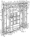
- FIG. 1 shows a motorized guide device 10 for cutting tools to reglaze and weatherize a window sash 74.
- the device comprises an adjustable rectangular frame which includes two vertical frame members 12 and 14 and two horizontal frame members 34 and 36 positioned between and substantially perpendicular to the vertical frame members thereby forming the adjustable rectangular frame.
- Connecting means 24 rotatably connect the horizontal frame members to the vertical frame members at each of four corners formed by intersection of the vertical and horizontal members.
- the connecting means could be formed from any rigid elements having circular openings at right angles to receive the vertical and horizontal frame members.
- a rigid rectangular frame 32 has two parallel vertical members 7 and 8 and two parallel horizontal members 9 and 11 rigidly connected to form a rectangular shape.
- a pair of parallel rigid vertical rod members 48 and 50 is secured between the horizontal members with each parallel rigid rod member adjacent to a vertical member of the sash clamping frame.
- a parallel pair of long L-shaped clamp members 52 and 54 is slidably attached to the rigid vertical rod members 48 and 50, perpendicular to the rigid vertical rod members.
- a power track 61 connects the two L-shaped clamp members 52 and 54.
- the power track comprises a shaft enclosing a movable track and a power wheel 60 which causes the track to move. Turning the power wheel in one direction causes the L-shaped clamp members to move closer together to clamp a sash 74 inbetween, and moving the power wheel in an opposite direction causes the L-shaped clamp members to move further apart to release the sash 74.
- a securing means 30 is attached to the frame at each of four corners of the adjustable rectangular frame for removably and vertically securing the adjustable rectangular frame reversibly to a window frame on a building and to the rigid vertical rectangular frame 32.
- Adjustable blocks of resilient material 31 with clamps on the securing means 30 enable the adjustable frame to be secured by tension.
- Bolts 22 from the rigid frame 32 may also be secured through plates 21 attached to vertical frame members 12 and 14 at connecting means 29.
- the horizontal frame members 34 and 36 are rigid cylindrical rods threaded along their length. A single threaded rod could be used as a drive, but two threaded rods produce a more even movement.
- the threaded rods 34 and 36 fit rotatably in the connecting means 24.
- the guide means 41 is movably connected to the horizontal frame members 34 and 36 by housings 42 and 44 respectively. In this case the guide means are mounted vertically between the horizontal frame members 34 and 36, but they could also be mounted horizontally between the vertical members 12 and 14.
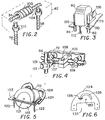
- housing 42 similar to housing 44, has a ball bearing collar 100 encircling the horizontal threaded rod 34 and bushings 102 and 104 encircling threaded guide rods 56 and 58.
- the ball bearings spirally arranged within the ball bearing collar 100 fit within the threads of each threaded rod to cause movement of the ball bearing collars reversibly along the threaded rods as the rods are rotated clockwise and counterclockwise.
- a motor 16 is connected to the adjustable frame on vertical member 12.
- a drive train reversibly turns the two threaded rods 34 and 36 simultaneously thereby causing the guide means 41 to move reversibly along the threaded rods.
- a drive shaft 18 may be used to turn worm gears 20 and rotate the horizontal threaded shafts 34 and 36 or a chain and sprockets (not shown) may be substituted as a drive means.
- the guide means 41 comprises a pair of parallel rigid cylindrical rods 56 and 58.
- the rods are threaded along their length.
- the threaded guide rods 56 and 58 fit rotatably at each end within a housing 42 and 44.
- a second motor 92 secured to the lower housing 44, rotates the threaded guide shafts 56 and 58 simultaneously by means of a drive shaft 94 and worm gears 20 or a chain and sprockets (not shown) thereby moving the cutting tool holding member 78 reversibly along the guide means.
- a tool holding plate 79 is movably connected to the threaded guide rods 56 and 58 by ball bearing collars similar to the collar shown in FIG. 2. As the second motor 92 rotates the threaded guide rods 56 and 58 reversibly the tool holding plate 79 moves up and down the guide rods.
- the tool receiving means comprises a pair of cylindrical receptacles 82 and 84 rigidly mounted on the cutting tool holding plate 79 to form a receptacle for a pair of springs 110 adjustably attached between the cylindrical receptacle and the cutting tool, a plungeable router 80 in this case.
- This spring connected tool receiving means enables the router 80 to be moved adjustably by handles 108 to a desired distance perpendicular to the plane of the adjustable rectangular frame allowing the router blade 112 to contact work surfaces at various distances, where it can be secured at the desired distance.
- the plungeable router 80 removes old glazing compound to remove the old single pane glass and routes deeper into the rabbit joints 76 to accommodate a double-paned insulating glass.
- a C-shaped rigid beam 26 is rigidly secured to the tops of the two vertical frame members 12 and 14 to form a track along the top of the motorized guide device.
- At least one roller 28 is securely attached to a top end of the rods of the guide device. The roller 28 or wheel fits into the track formed by the C-shaped rigid beam 26, thereby supporting the weight of the guide device 41 as it moves along the track, helping to prevent sagging of the horizontal rods which could lead to inaccuracy.
- a pair of parallel horizontal smooth cylindrical rods 23 and 43 are rigidly attached to the vertical frame members 12 and 14 along extensions of the vertical frame members above and below the first horizontal frame members 34 and 36, respectively.
- a second guide means 69 is movably connected to the smooth rods by housings 62 and 64.
- the second guide member comprises a pair of rigid cylindrical rods 66 and 68 forming second guide rods movably mounted in a vertical orientation between the two smooth horizontal rods 23 and 43 and perpendicular to the horizontal frame members.
- the housing 62 for the second guide means has two pair of grooved rollers 107 and 109 riding on the horizontal smooth rod 23 and a clamp 105 with a knob 103 for tightening the clamp around the smooth rod 23.
- the upper tool holding means on the second guide means 81 comprises a rigid plate 75 having two rigidly connected flanges each with a pair of ball bearing bushings 49 movably secured around the smooth guide rods 66 and 68. Chrome rods and ball bearings insure accurate movement.
- the upper cutting tool 73 is a rotary saw rigidly attached to the cutting tool holding plate 75.
- a spring loaded metal band pulley 46 is attached to the top housing 62 of the second guide means. An end of the metal band attaches to the rotary saw to help support it.
- a weight on a cord and pulley may be attached to the top housing of the second guide means, wherein an end of the cord attaches to the rotary saw to help support it.
- a spring loaded clip 47 is attached to the top housing 62 of the second guide means to engage the rotary saw and hold it when not in use.
- the clip 47 is released, the rotary saw 73 slides down the smooth guide rods to trim sash sides evenly and smoothly on two opposite parallel sides of a sash to accommodate a weatherized air-tight track between the window frame and the sash.
- a guide centering device 93 is mounted above the upper smooth horizontal rod 23 parallel to the horizontal frame members and perpendicular to the guide rods for limiting the movement of the second guide member 69 to position a cutting tool into at least two operating positions which are equidistant from the center of the centering guide device.
- the guide centering device comprises a rigid centering rod 25 extending horizontally rotatably connected to a top portion of the first and second vertical frame members 12 and 14. At one end of the guide centering rod 25 is a rigidly connected crank 39 for turning the guide centering rod.
- the guide centering rod is threaded from the center of the rod outwardly with right screw threads in one direction and left screw threads in the opposite direction.
- a depressable spring-loaded guide centering stop 27 and 37 is mounted on each side of the center of the guide centering rod evenly spaced from the center. Turning the crank 39 rotates the guide centering rod 25 causing each of the guide centering stops 27 and 37 to move along the threads of the rod an equal distance from the center to stop the second guide member 69 and position a cutting tool.
- each smooth guide rod 66 and 68 stop engaging tabs 33 and 35 are rigidly attached to engage the stops 27 and 37 respectively to stop the panel saw in positions equidistant from the center of the centering rod 25 to insure even cuts on both sides of the sash 74.
- a sash centering means 59 comprises a sash centering rod 63 mounted rotatably on one of the L-shaped clamping members 54 parallel to the L-shaped clamping member.
- a crank 65 turns the sash centering rod.
- the sash centering rod 63 is threaded from the center of the rod outwardly with right screw threads in one direction and left screw threads in the opposite direction.
- One depressable spring-loaded sash centering stop 55 and 57 is mounted on each side of the center of the sash centering rod evenly spaced from the center.
- crank 65 rotates the sash centering rod 63 causing each of the sash centering stops 55 and 57 to move along the threads of the rod an equal distance from the center and each sash centering stop engages a side of a window sash 74 to center the sash.
- the guide centering device 93 and the sash centering device 59 together insure that the sash will be trimmed evenly and accurately on both sides of the sash to provide an airtight fit with a weatherized track on the window frame.
- a lower cutting tool mounting means 91 comprises a swivel plate 124 adjustably attached to the cutting tool holding member 72 (FIG. 1) to permit rotation of the cutting tool (in this case, rotary saw 70) within the plane of the adjustable rectangular frame.
- a semicircular slot 128 on the swivel plate 124 admits a bolt from the tool holding member.
- the swivel plate may be turned to the desired angle and secured in place by a thumb screw 126.
- the rotary saw is moved adjustably to a desired distance perpendicular to the plane of the adjustable rectangular frame by adjusting the depth of the saw blade 118 relative to the saw guide plate 123.
- the rotary saw 70 of FIG. 5 further comprises a pair of guide pins 120 and 122 connected by a rigid bar 121 securely attached to the rotary saw by screws or rivets.
- One guide pin 122 is positioned directly in front of the cutting edge of the rotary blade 118 and the other guide pin 120 is positioned directly behind the cutting edge of the rotary blade to prevent overcutting in cutting slots in the rabbit joints 76 on window sashes.
- the guide pins position the blade of the saw away from the window frame adjacent to the rabbit joint 76.
- the swivel plate 124 enables the rotary saw to be turned vertically and horizontally to work on all of the rabbit joints in a sash.
- the rotary saw 70 cuts slots in rabbit joints to receive the glazing beads for retaining the double-pane glass.
- the cutting tools may be moved over the entire vertical plane (X and Y directions) because of combined vertical and horizontal movement and also over a wide range of distance in the Z direction toward the work because of the spring connection as well as adjustments of the tools themselves. They may be operated at any angle or over any curved surface as in the case of arched windows.
Landscapes
- Engineering & Computer Science (AREA)
- Life Sciences & Earth Sciences (AREA)
- Mechanical Engineering (AREA)
- Wood Science & Technology (AREA)
- Forests & Forestry (AREA)
- Processing Of Stones Or Stones Resemblance Materials (AREA)
- Drilling Tools (AREA)
- Investigating Or Analyzing Materials By The Use Of Magnetic Means (AREA)
- Pinball Game Machines (AREA)
- Adjustment And Processing Of Grains (AREA)
- Milling, Drilling, And Turning Of Wood (AREA)
- Door And Window Frames Mounted To Openings (AREA)
- Earth Drilling (AREA)
Claims (10)
- Motorisierte Führungsvorrichtung für Schneidwerkzeuge zum Nach- bzw. Wiederverglasen und Wetterfestmachen eines schiebbaren Fensterrahmens, wobei die Vorrichtung folgendes umfaßt:einen einstellbaren rechteckigen Rahmen, umfassend:ein erstes und ein zweites vertikales Rahmenelement bzw. -teil (12, 14) undein erstes und ein zweites horizontales Rahmenelement bzw. -teil (34, 36), die zwischen und im wesentlichen rechtwinkelig zum ersten und zweiten vertikalen Rahmenelement positioniert sind, wodurch der einstellbare rechteckige Rahmen entsteht;Verbindungsmittel (24), die die vertikalen Rahmenelemente mit den horizontalen Rahmenelementen an jeder der vier Ecken, die durch den Schnittpunkt der vertikalen und horizontalen Elemente gebildet werden, drehbar verbinden;ein Führungsmittel (41), das beweglich zwischen zwei gegenüberliegenden Rahmenelementen parallel zur Ebene des rechteckigen Rahmens montiert ist; worin das Führungsmittel (41) in vertikaler Ausrichtung zwischen den zwei horizontalen Rahmenelementen (34, 36) montiert ist und die motorisierte Führungsvorrichtung weiters einen C-förmigen starren Balken (26), der starr an den oberen Enden der zwei vertikalen Rahmenelemente (12, 14) befestigt ist, um eine Schiene entlang des oberen Endes der motorisierten Führungsvorrichtung zu bilden, und zumindest eine Rolle (28) umfaßt, die fix an einem Spitzenende des Führungsmittels (41) angebracht ist, welche Rolle (28) in die durch den C-förmigen starren Balken (26) gebildete Schiene paßt, wodurch das Gewicht des Führungsmittels (41) während dessen Fortbewegung entlang der Schiene abgestützt wird;ein erstes motorisiertes Mittel (16), das die Kraft liefert, das Führungsmittel (41) reversibel entlang der zwei gegenüberliegenden horizontalen Rahmenelemente (34, 36) zu bewegen;ein Schneidwerkzeug-Halterungselement (78), das beweglich am Führungsmittel montiert ist, um für Bewegung entlang des Führungsmittels zu sorgen;ein Schneidwerkzeug-Montagemittel auf bzw. an dem Schneidwerkzeug-Halterungselement (78), das eine einstellbare Bewegung des Schneidwerkzeugs in einer zur Ebene des einstellbaren rechteckigen Rahmens rechtwinkelig positionierten Richtung ermöglicht;ein am einstellbaren rechteckigen Rahmen befestigter, starrer, vertikaler, rechteckiger Rahmen (32) mit einem Fensterrahmen-Klemmittel;ein am Rahmen an jeder der vier Ecken des einstellbaren rechteckigen Rahmens angebrachtes Befestigungsmittel (30), um den einstellbaren rechteckigen Rahmen entfernbar, vertikal und reversibel an einem Fensterrahmen an einem Gebäude und am starren, vertikalen, rechteckigen Rahmen zu befestigen.
- Vorrichtung nach Anspruch 1, worin der starre, vertikale, rechteckige Rahmen (32) mit einem Fensterrahmen-Klemmittel folgendes umfaßt:einen starren rechteckigen Rahmen mit zwei parallelen vertikalen Elementen (7, 8) und zwei parallelen horizontalen Elementen (9, 11), die starr verbunden sind, um eine rechteckige Form zu bilden;ein Paar paralleler starrer Stangenelemente (48, 50), die zwischen den horizontalen Elementen befestigt sind, wobei jedes parallele starre Stangenelement angrenzend zu einem vertikalen Element des Fensterrahmen-Klemmrahmens angeordnet ist;ein paralleles Paar langer L-förmiger Klemmelemente (52, 54), die gleitend an den starren Stangenelementen senkrecht zu den starren Stangenelementen befestigt sind;eine Kraftschiene (61), die die zwei L-förmigen Klemmelemente (52, 54) verbindet, worin die Kraftschiene (61) eine Welle umfaßt, die eine bewegliche Schiene und ein Kraftrad (60) umschließt, das die Bewegung der Schiene verursacht, worin das Drehen des Kraftrads in einer Richtung bewirkt, daß sich die L-förmigen Klemmelemente näher zueinanderbewegen, um einen Fensterrahmen dazwischen einzuklemmen, und das Drehen des Kraftrads in der entgegengesetzten Richtung bewirkt, daß sich die L-förmigen Klemmelemente voneinander wegbewegen, um den Fensterrahmen zu lösen.
- Vorrichtung nach Anspruch 2, worin das gegenüberliegende Paar Rahmenelemente, an dem das Führungsmittel (41) im einstellbaren Rahmen montiert ist, ein erstes Paar paralleler, starrer, zylindrischer Stangen (34, 36) ist, von denen zumindest eine auf ihrer Länge mit einem Gewinde versehen ist, wobei die Gewindestange drehbar in das Verbindungsmittel (24) paßt, und worin das Führungsmittel (41) durch ein bewegliches Gehäusemittel (42) beweglich mit der Gewindestange verbunden ist, und worin das erste motorisierte Antriebsmittel (16) folgendes umfaßt:
einen ersten Motor, der mit dem einstellbaren Rahmen und einem ersten Antriebszugmittel verbunden ist, um die Gewindestange reversibel zu drehen, wodurch bewirkt wird, daß sich das Führungsmittel (41) reversibel entlang des ersten Paars starrer zylindrischer Stangen bewegt. - Vorrichtung nach Anspruch 3, worin das Führungsmittel (41) ein zweites Paar paralleler, starrer, zylindrischer Stangen (56, 58) umfaßt, die Führungsstangen bilden, die rechtwinkelig zum ersten Paar zylindrischer Stangen (34, 36) angeordnet und durch ein bewegliches Gehäuse (42) mit den zylindrischen Stangen verbunden sind, worin zumindest eine der Führungsstangen auf ihrer Länge mit einem Gewinde versehen ist, um eine Gewindeführungsstange zu bilden, die drehbar an jedem Ende in das Gehäuse (42) paßt, worin das Schneidwerkzeug-Halterungselement ein bewegliches Werkzeughalterungs-Gehäusemittel enthält, worin die Vorrichtung weiters ein zweites motorisiertes Mittel (92) zum Bewegen des Schneidwerkzeug-Halterungselements in reversibler Weise entlang des Führungsmittels (41) umfaßt, wobei das zweite motorisierte Antriebsmittel folgendes enthält:
einen zweiten Motor (92), der mit einem der Gehäuse verbunden ist, und ein zweites Antriebszugmittel, um die Gewindeführungsstange reversibel zu drehen, wodurch sich das Werkzeughalterungselement reversibel entlang der Führungsstangen bewegt. - Vorrichtung nach Anspruch 4, worin das Schneidwerkzeug-Montagemittel folgendes umfaßt:
ein Paar zylindrischer Aufnahmen (82, 84), die starr auf dem Schneidwerkzeug-Halterungselement montiert sind, worin ein Federnpaar (110) einstellbar zwischen der zylindrischen Aufnahme und dem Schneidwerkzeug befestigt ist, wodurch dieses in der Lage ist, einstellbar über eine erwünschte Distanz senkrecht zur Ebene des einstellbaren rechteckigen Rahmens bewegt zu werden; worin das Schneidwerkzeug ein Senkfräser ist. - Vorrichtung nach Anspruch 2, weiters umfassend ein zweites Führungsmittel (69), worin das zweite Führungsmittel ein Paar starrer zylindrischer Stangen (66, 68) enthält, die zweite Führungsstangen bilden, die in einer vertikalen Ausrichtung zwischen den zwei horizontalen Rahmenelementen und rechtwinkelig zu den horizontalen Rahmenelementen beweglich montiert sind, worin zumindest ein Schneidwerkzeug auf dem Schneidwerkzeug-Halterungselement des zweiten Führungsmittels montiert ist und worin die Vorrichtung weiters eine Führungszentriervorrichtung (93) parallel zu den horizontalen Rahmenelementen und rechtwinkelig zu den Führungsstangen umfaßt, um die Bewegung des zweiten Führungselements zu begrenzen, um ein Schneidwerkzeug in zumindest zwei Betriebspositionen zu positionieren, die sich in einem gleichen Abstand vom Mittelpunkt der Zentrierführungsvorrichtung befinden.
- Vorrichtung nach Anspruch 6, worin die Führungszentriervorrichtung folgendes umfaßt: eine starre Zentrierstange (25), die horizontal verläuft und drehbar mit einem Spitzenabschnitt des ersten und des zweiten vertikalen Rahmenelements verbunden ist, und ein Kurbel mittel (39) zum Drehen der Führungszentrierstange, worin die Führungszentrierstange vom Mittelpunkt der Stange nach außen in eine Richtung mit einem Rechtsschraubengewinde und in die andere Richtung mit einem Linksschraubengewinde versehen ist, und worin eine Führungszentrierungs-Stoppvorrichtung (27, 37) auf jeder Seite des Mittelpunkts der Führungszentrierstange im gleichen Abstand vom Mittelpunkt montiert ist, sodaß das Drehen des Kurbel mittels eine Drehung der Führungszentrierstange bewirkt, wodurch sich jede der Führungszentrierungs-Stoppvorrichtungen entlang der Gewinde der Stange um einen gleichen Abstand vom Mittelpunkt bewegt, um das zweite Führungsmittel anzuhalten und ein Schneidwerkzeug zu positionieren.
- Vorrichtung nach Anspruch 7, weiters umfassend ein Fensterrahmenzentriermittel (59), bestehend aus einer Fensterrahmenzentrierstange (63), die drehbar auf einem der L-förmigen Klemmelemente (54) parallel zum L-förmigen Klemmelement montiert ist, und ein Kurbelmittel zum Drehen der Fensterrahmenzentrierstange, die vom Mittelpunkt der Stange nach außen in eine Richtung mit einem Rechtsschraubengewinde und in die andere Richtung mit einem Linksschraubengewinde versehen ist, und worin eine Fensterrahmenzentrierungs-Stoppvorrichtung (55, 57) auf jeder Seite des Mittelpunkts der Fensterrahmenzentrierstange im gleichen Abstand vom Mittelpunkt montiert ist, sodaß das Drehen des Kurbelmittels die Fensterrahmenzentrierstange dreht, wodurch sich jede der Fensterrahmenzentrierungs-Stoppvorrichtungen entlang der Gewinde der Stange über eine gleiche Entfernung vom Mittelpunkt bewegt und jede Fensterrahmenzentrierungs-Stoppvorrichtung an einer Seite eines Fensterrahmens angreift, um den Fensterrahmen zu zentrieren; worin das Schneidwerkzeug eine Kreissäge ist, die starr am Schneidwerkzeug-Halterungselement befestigt ist, das gleitend am zweiten Führungsmittel angebracht ist, um einen Fensterrahmen gleichmäßig auf zwei gegenüberliegenden parallelen Seiten eines Fensterrahmens zuzurichten.
- Vorrichtung nach Anspruch 2, weiters umfassend ein zweites Führungsmittel (69), das ein Paar starrer zylindrischer Stangen (66, 68) umfaßt, die zweite Führungsstangen bilden, die in einer vertikalen Ausrichtung zwischen den zwei horizontalen Rahmenelementen und senkrecht zu den horizontalen Rahmenelementen beweglich montiert sind, worin zumindest ein Schneidwerkzeug auf dem Schneidwerkzeug-Halterungselement des zweiten Führungsmittels montiert ist, worin das Schneidwerkzeug eine Kreissäge mit einer Blatttiefeneinstellung ist und das Schneidwerkzeug-Halterungsmittel eine Schwenkplatte umfaßt, die einstellbar am Schneidwerkzeug-Halterungselement befestigt ist, um die Drehung der Kreissäge innerhalb der Ebene des einstellbaren rechteckigen Rahmens zu ermöglichen.
- Vorrichtung nach Anspruch 9, worin die Kreissäge weiters ein Paar Führungsstifte umfaßt, die an der Kreissäge befestigt sind, wobei ein Führungsstift direkt vor der Schneidkante des Kreissägeblatts und der andere Führungsstift direkt hinter der Schneidkante des Kreissägeblatts positioniert ist, um Überschneiden zu vermeiden.
Applications Claiming Priority (2)
| Application Number | Priority Date | Filing Date | Title |
|---|---|---|---|
| US07/934,857 US5253400A (en) | 1992-08-24 | 1992-08-24 | Motorized guide for grouting and sawing window sashes |
| US934857 | 1992-08-24 |
Publications (3)
| Publication Number | Publication Date |
|---|---|
| EP0585064A2 EP0585064A2 (de) | 1994-03-02 |
| EP0585064A3 EP0585064A3 (de) | 1994-10-05 |
| EP0585064B1 true EP0585064B1 (de) | 1996-11-20 |
Family
ID=25466188
Family Applications (1)
| Application Number | Title | Priority Date | Filing Date |
|---|---|---|---|
| EP93306592A Expired - Lifetime EP0585064B1 (de) | 1992-08-24 | 1993-08-20 | Motorisierte Führung zum Ausfräsen und Sägen von Schiebefenstern |
Country Status (7)
| Country | Link |
|---|---|
| US (1) | US5253400A (de) |
| EP (1) | EP0585064B1 (de) |
| AT (1) | ATE145447T1 (de) |
| AU (1) | AU668402B2 (de) |
| CA (1) | CA2104500A1 (de) |
| DE (1) | DE69306066T2 (de) |
| NZ (1) | NZ248464A (de) |
Cited By (1)
| Publication number | Priority date | Publication date | Assignee | Title |
|---|---|---|---|---|
| CN104074441A (zh) * | 2014-06-19 | 2014-10-01 | 德清艾希德卫浴洁具有限公司 | 淋浴房玻璃固定机构 |
Families Citing this family (22)
| Publication number | Priority date | Publication date | Assignee | Title |
|---|---|---|---|---|
| JPH0790437B2 (ja) * | 1992-05-12 | 1995-10-04 | 健 柳沢 | 2次元運動機構 |
| GB2324759B (en) * | 1997-05-01 | 1999-10-20 | Britannia Commerce Limited | Apparatus for machining vertical panels |
| FI110584B (fi) * | 1997-05-05 | 2003-02-28 | Rautaruukki Oy | Koksausuunin ovenkarmin tiivistepinnan työstö |
| IT1295636B1 (it) * | 1997-10-22 | 1999-05-24 | Selco Spa | Macchina sezionatrice per il taglio di corpi piani. |
| IT1318111B1 (it) * | 2000-07-03 | 2003-07-23 | Re M S R L | Macchina foratrice per pannelli |
| US7555976B2 (en) * | 2002-05-30 | 2009-07-07 | Tapco International Corporation | Portable saw table assembly |
| WO2005077624A1 (de) * | 2004-02-17 | 2005-08-25 | Stuckateur- + Malerbetrieb Heinz Schmider | Vorrichtung zum bearbeiten von plattenförmigen gegenständen, vorrichtung zur veränderung der arbeitsposition eines werkzeuges, verfahren zur bearbeitung von plattenförmigen gegenständen |
| US7354227B2 (en) * | 2004-05-20 | 2008-04-08 | Pro-Line Automation Systems Ltd. | Apparatus and method for manufacturing plastic frameworks such as window frames |
| US7779737B2 (en) * | 2004-08-12 | 2010-08-24 | The Chisel Works, LLC. | Multi-axis panel saw |
| US20060060049A1 (en) * | 2004-09-21 | 2006-03-23 | Stanley Learnard | Panel saw |
| US20060123962A1 (en) * | 2004-11-23 | 2006-06-15 | Norston Fontaine | Portable saw guide |
| DE102006061235B4 (de) * | 2006-12-22 | 2019-06-06 | Robert Bosch Gmbh | Oberfräse |
| KR100921985B1 (ko) * | 2007-09-10 | 2009-10-14 | (주)케이엘메드 | 보행 재활 기구의 보행 궤적 유도 장치 |
| JP2009113216A (ja) * | 2007-11-01 | 2009-05-28 | Makita Corp | ルータ |
| US20100077877A1 (en) * | 2008-09-26 | 2010-04-01 | Ming-Hung Hsieh | Rotary micro-adjustment mechanism for a synchronous double-drive positioning platform |
| CA2752168A1 (en) * | 2009-02-13 | 2010-08-19 | Black & Decker Inc. | Router |
| US20170008188A1 (en) * | 2015-07-10 | 2017-01-12 | Justin Staffen | Cutting apparatus |
| US11155001B2 (en) * | 2018-03-21 | 2021-10-26 | Safety Speed Cut Manufacturing Co., Inc. | Panel cutter with efficient and effective clamping system |
| CN108973474A (zh) * | 2018-10-12 | 2018-12-11 | 湖州张师傅胎毛文化有限公司 | 一种胎毛笔笔杆加工装置 |
| CN113720587B (zh) * | 2021-06-07 | 2024-12-13 | 重庆大学 | 一种竖向加载系统及在竖向加载条件下的构件侧向受力测试方法 |
| CH718875B9 (de) * | 2021-08-04 | 2024-09-30 | Striebig Ag | Vertikale Plattensäge mit Plattenabsenkvorrichtung. |
| CN116275196B (zh) * | 2023-05-22 | 2023-08-15 | 安徽维鸿电子科技有限公司 | 一种插片散热器定位钻孔加工设备 |
Family Cites Families (10)
| Publication number | Priority date | Publication date | Assignee | Title |
|---|---|---|---|---|
| US1825684A (en) * | 1928-07-26 | 1931-10-06 | Cons Machine Tool Corp Of Amer | Milling machine |
| US2113016A (en) * | 1938-02-02 | 1938-04-05 | Rene J Demers | Process of removing glass and putty from sash |
| US3557659A (en) * | 1969-05-08 | 1971-01-26 | United States Steel Corp | Apparatus for machining coke oven door jambs |
| US4102245A (en) * | 1976-04-28 | 1978-07-25 | Hallmor, Inc. | Door frame truing apparatus |
| FR2501563B1 (fr) * | 1981-03-10 | 1986-07-18 | Sormel Sa | Manipulateur automatique |
| FR2600277B1 (fr) * | 1986-06-20 | 1988-10-21 | Dassonville Joel | Dispositif de pilotage automatique d'un outil, notamment pour les travaux de finition de menuiseries |
| US4787786A (en) * | 1987-08-24 | 1988-11-29 | Freud Ivan B | Laminate cutting device |
| US4830555A (en) * | 1988-01-11 | 1989-05-16 | Conachen James A | Guide for window grouting device |
| US4995277A (en) * | 1988-05-31 | 1991-02-26 | Ken Yanagisawa | Two dimensional drive system |
| US5106243A (en) * | 1990-09-28 | 1992-04-21 | Climax Portable Machine Tools, Inc. | Portable machine tool |
-
1992
- 1992-08-24 US US07/934,857 patent/US5253400A/en not_active Expired - Lifetime
-
1993
- 1993-08-20 AT AT93306592T patent/ATE145447T1/de not_active IP Right Cessation
- 1993-08-20 DE DE69306066T patent/DE69306066T2/de not_active Expired - Fee Related
- 1993-08-20 CA CA 2104500 patent/CA2104500A1/en not_active Abandoned
- 1993-08-20 EP EP93306592A patent/EP0585064B1/de not_active Expired - Lifetime
- 1993-08-23 AU AU44804/93A patent/AU668402B2/en not_active Ceased
- 1993-08-23 NZ NZ248464A patent/NZ248464A/en unknown
Cited By (2)
| Publication number | Priority date | Publication date | Assignee | Title |
|---|---|---|---|---|
| CN104074441A (zh) * | 2014-06-19 | 2014-10-01 | 德清艾希德卫浴洁具有限公司 | 淋浴房玻璃固定机构 |
| CN104074441B (zh) * | 2014-06-19 | 2015-09-09 | 德清艾希德卫浴洁具有限公司 | 淋浴房玻璃固定机构 |
Also Published As
| Publication number | Publication date |
|---|---|
| EP0585064A2 (de) | 1994-03-02 |
| NZ248464A (en) | 1995-10-26 |
| AU668402B2 (en) | 1996-05-02 |
| ATE145447T1 (de) | 1996-12-15 |
| DE69306066D1 (de) | 1997-01-02 |
| DE69306066T2 (de) | 1997-04-10 |
| US5253400A (en) | 1993-10-19 |
| CA2104500A1 (en) | 1994-02-25 |
| AU4480493A (en) | 1994-03-03 |
| EP0585064A3 (de) | 1994-10-05 |
Similar Documents
| Publication | Publication Date | Title |
|---|---|---|
| US5253400A (en) | Motorized guide for grouting and sawing window sashes | |
| US4516612A (en) | Multipurpose table saw | |
| US3323507A (en) | Concrete cutting machine | |
| EP2432618B1 (de) | Werkzeugmaschine | |
| US11376696B2 (en) | Converting a CNC milling machine to a CNC wire saw | |
| US4830555A (en) | Guide for window grouting device | |
| KR101859164B1 (ko) | 절단각도 가변형 석재 절단기 | |
| US6877238B2 (en) | System for precision miter cutting | |
| US20130139663A1 (en) | Panel saw and method of operation | |
| USRE17087E (en) | Pekcy leon billingrsley | |
| CN119772257A (zh) | 一种断桥铝型材切割锯床 | |
| US6736043B1 (en) | Apparatus for machining vertical panels | |
| CN118060910A (zh) | 一种锯切端铣一体机 | |
| CN210208884U (zh) | 一种铝合金节能防火窗用双角锯床 | |
| US2949826A (en) | Device for removing and routing putties and other material | |
| CN224158651U (zh) | 一种玻璃多角度切割机 | |
| CN212795476U (zh) | 便携式板材切割器 | |
| CN220052013U (zh) | 一种切槽机 | |
| CN223737942U (zh) | 一种光学玻璃切削装置 | |
| GB2182280A (en) | Improvements in or relating to guide apparatus for cutting tools | |
| CN223733899U (zh) | 一种门窗锁孔槽加工设备 | |
| US20230100775A1 (en) | Portable digital device for machining a workpiece | |
| CN113275641B (zh) | 铝门窗组角机 | |
| CN220516935U (zh) | 一种门窗型材在线压条切割装置 | |
| CN219900473U (zh) | 一种铝门窗型材双头数控切割锯 |
Legal Events
| Date | Code | Title | Description |
|---|---|---|---|
| PUAI | Public reference made under article 153(3) epc to a published international application that has entered the european phase |
Free format text: ORIGINAL CODE: 0009012 |
|
| AK | Designated contracting states |
Kind code of ref document: A2 Designated state(s): AT BE CH DE DK ES FR GB GR IE IT LI LU MC NL PT SE |
|
| PUAL | Search report despatched |
Free format text: ORIGINAL CODE: 0009013 |
|
| AK | Designated contracting states |
Kind code of ref document: A3 Designated state(s): AT BE CH DE DK ES FR GB GR IE IT LI LU MC NL PT SE |
|
| 17P | Request for examination filed |
Effective date: 19950404 |
|
| 17Q | First examination report despatched |
Effective date: 19951005 |
|
| GRAH | Despatch of communication of intention to grant a patent |
Free format text: ORIGINAL CODE: EPIDOS IGRA |
|
| GRAH | Despatch of communication of intention to grant a patent |
Free format text: ORIGINAL CODE: EPIDOS IGRA |
|
| GRAA | (expected) grant |
Free format text: ORIGINAL CODE: 0009210 |
|
| AK | Designated contracting states |
Kind code of ref document: B1 Designated state(s): AT BE CH DE DK ES FR GB GR IE IT LI LU MC NL PT SE |
|
| PG25 | Lapsed in a contracting state [announced via postgrant information from national office to epo] |
Ref country code: LI Effective date: 19961120 Ref country code: IT Free format text: LAPSE BECAUSE OF FAILURE TO SUBMIT A TRANSLATION OF THE DESCRIPTION OR TO PAY THE FEE WITHIN THE PRE;WARNING: LAPSES OF ITALIAN PATENTS WITH EFFECTIVE DATE BEFORE 2007 MAY HAVE OCCURRED AT ANY TIME BEFORE 2007. THE CORRECT EFFECTIVE DATE MAY BE DIFFERENT FROM THE ONE RECORDED.SCRIBED TIME-LIMIT Effective date: 19961120 Ref country code: GR Free format text: LAPSE BECAUSE OF FAILURE TO SUBMIT A TRANSLATION OF THE DESCRIPTION OR TO PAY THE FEE WITHIN THE PRESCRIBED TIME-LIMIT Effective date: 19961120 Ref country code: ES Free format text: THE PATENT HAS BEEN ANNULLED BY A DECISION OF A NATIONAL AUTHORITY Effective date: 19961120 Ref country code: DK Effective date: 19961120 Ref country code: CH Effective date: 19961120 Ref country code: BE Effective date: 19961120 Ref country code: AT Effective date: 19961120 |
|
| REF | Corresponds to: |
Ref document number: 145447 Country of ref document: AT Date of ref document: 19961215 Kind code of ref document: T |
|
| REG | Reference to a national code |
Ref country code: IE Ref legal event code: FG4D Free format text: 70690 |
|
| REF | Corresponds to: |
Ref document number: 69306066 Country of ref document: DE Date of ref document: 19970102 |
|
| PG25 | Lapsed in a contracting state [announced via postgrant information from national office to epo] |
Ref country code: SE Effective date: 19970220 Ref country code: PT Effective date: 19970220 |
|
| ET | Fr: translation filed | ||
| ET | Fr: translation filed |
Free format text: CORRECTIONS |
|
| REG | Reference to a national code |
Ref country code: CH Ref legal event code: PL |
|
| PGFP | Annual fee paid to national office [announced via postgrant information from national office to epo] |
Ref country code: FR Payment date: 19970820 Year of fee payment: 5 |
|
| PGFP | Annual fee paid to national office [announced via postgrant information from national office to epo] |
Ref country code: NL Payment date: 19970826 Year of fee payment: 5 |
|
| PGFP | Annual fee paid to national office [announced via postgrant information from national office to epo] |
Ref country code: DE Payment date: 19970827 Year of fee payment: 5 |
|
| PG25 | Lapsed in a contracting state [announced via postgrant information from national office to epo] |
Ref country code: LU Free format text: LAPSE BECAUSE OF NON-PAYMENT OF DUE FEES Effective date: 19970831 |
|
| PLBE | No opposition filed within time limit |
Free format text: ORIGINAL CODE: 0009261 |
|
| STAA | Information on the status of an ep patent application or granted ep patent |
Free format text: STATUS: NO OPPOSITION FILED WITHIN TIME LIMIT |
|
| 26N | No opposition filed | ||
| PG25 | Lapsed in a contracting state [announced via postgrant information from national office to epo] |
Ref country code: MC Free format text: LAPSE BECAUSE OF NON-PAYMENT OF DUE FEES Effective date: 19980228 |
|
| PG25 | Lapsed in a contracting state [announced via postgrant information from national office to epo] |
Ref country code: NL Free format text: LAPSE BECAUSE OF NON-PAYMENT OF DUE FEES Effective date: 19990301 |
|
| PG25 | Lapsed in a contracting state [announced via postgrant information from national office to epo] |
Ref country code: FR Free format text: LAPSE BECAUSE OF NON-PAYMENT OF DUE FEES Effective date: 19990430 |
|
| NLV4 | Nl: lapsed or anulled due to non-payment of the annual fee |
Effective date: 19990301 |
|
| PG25 | Lapsed in a contracting state [announced via postgrant information from national office to epo] |
Ref country code: DE Free format text: LAPSE BECAUSE OF NON-PAYMENT OF DUE FEES Effective date: 19990601 |
|
| REG | Reference to a national code |
Ref country code: FR Ref legal event code: ST |
|
| PGFP | Annual fee paid to national office [announced via postgrant information from national office to epo] |
Ref country code: GB Payment date: 20000810 Year of fee payment: 8 |
|
| PGFP | Annual fee paid to national office [announced via postgrant information from national office to epo] |
Ref country code: IE Payment date: 20000822 Year of fee payment: 8 |
|
| PG25 | Lapsed in a contracting state [announced via postgrant information from national office to epo] |
Ref country code: IE Free format text: LAPSE BECAUSE OF NON-PAYMENT OF DUE FEES Effective date: 20010820 Ref country code: GB Free format text: LAPSE BECAUSE OF NON-PAYMENT OF DUE FEES Effective date: 20010820 |
|
| GBPC | Gb: european patent ceased through non-payment of renewal fee |
Effective date: 20010820 |
|
| REG | Reference to a national code |
Ref country code: IE Ref legal event code: MM4A |