EP0584714A1 - System zur Verabreichung einer medizinischen Lösung - Google Patents
System zur Verabreichung einer medizinischen Lösung Download PDFInfo
- Publication number
- EP0584714A1 EP0584714A1 EP93113225A EP93113225A EP0584714A1 EP 0584714 A1 EP0584714 A1 EP 0584714A1 EP 93113225 A EP93113225 A EP 93113225A EP 93113225 A EP93113225 A EP 93113225A EP 0584714 A1 EP0584714 A1 EP 0584714A1
- Authority
- EP
- European Patent Office
- Prior art keywords
- plunger
- container
- medical solution
- delivery system
- solution delivery
- Prior art date
- Legal status (The legal status is an assumption and is not a legal conclusion. Google has not performed a legal analysis and makes no representation as to the accuracy of the status listed.)
- Withdrawn
Links
Images


Classifications
-
- A—HUMAN NECESSITIES
- A61—MEDICAL OR VETERINARY SCIENCE; HYGIENE
- A61M—DEVICES FOR INTRODUCING MEDIA INTO, OR ONTO, THE BODY; DEVICES FOR TRANSDUCING BODY MEDIA OR FOR TAKING MEDIA FROM THE BODY; DEVICES FOR PRODUCING OR ENDING SLEEP OR STUPOR
- A61M5/00—Devices for bringing media into the body in a subcutaneous, intra-vascular or intramuscular way; Accessories therefor, e.g. filling or cleaning devices, arm-rests
- A61M5/14—Infusion devices, e.g. infusing by gravity; Blood infusion; Accessories therefor
- A61M5/142—Pressure infusion, e.g. using pumps
- A61M5/145—Pressure infusion, e.g. using pumps using pressurised reservoirs, e.g. pressurised by means of pistons
- A61M5/1452—Pressure infusion, e.g. using pumps using pressurised reservoirs, e.g. pressurised by means of pistons pressurised by means of pistons
- A61M5/1454—Pressure infusion, e.g. using pumps using pressurised reservoirs, e.g. pressurised by means of pistons pressurised by means of pistons spring-actuated, e.g. by a clockwork
-
- A—HUMAN NECESSITIES
- A61—MEDICAL OR VETERINARY SCIENCE; HYGIENE
- A61M—DEVICES FOR INTRODUCING MEDIA INTO, OR ONTO, THE BODY; DEVICES FOR TRANSDUCING BODY MEDIA OR FOR TAKING MEDIA FROM THE BODY; DEVICES FOR PRODUCING OR ENDING SLEEP OR STUPOR
- A61M5/00—Devices for bringing media into the body in a subcutaneous, intra-vascular or intramuscular way; Accessories therefor, e.g. filling or cleaning devices, arm-rests
- A61M5/14—Infusion devices, e.g. infusing by gravity; Blood infusion; Accessories therefor
- A61M5/142—Pressure infusion, e.g. using pumps
- A61M5/145—Pressure infusion, e.g. using pumps using pressurised reservoirs, e.g. pressurised by means of pistons
- A61M5/1452—Pressure infusion, e.g. using pumps using pressurised reservoirs, e.g. pressurised by means of pistons pressurised by means of pistons
- A61M5/1456—Pressure infusion, e.g. using pumps using pressurised reservoirs, e.g. pressurised by means of pistons pressurised by means of pistons with a replaceable reservoir comprising a piston rod to be moved into the reservoir, e.g. the piston rod is part of the removable reservoir
Definitions
- the present invention relates to a medical solution delivery system and, more particularly, a system suitable for continuously delivering a certain amount of a medical solution to a blood vessel, extraduramater, subcutaneous tissue, or the bladder of a patient by little and little.
- Such delivery system comprises an expanded balloon of an elastic material with a medical solution filled therein, a housing for holding the balloon therein, and a flow control means connected to the balloon to control a flow rate of the solution.
- the medical solution is delivered from the balloon little by little by means of shrinkage thereof.
- the balloon is used as a container for storing a medical solution and as a motive power source for delivering the solution therefrom.
- the balloon is made of an elastomeric gum rubber, the force applied to the medical solution varies with time during injection, thus making it impossible to delivery a fixed amount of the medical solution at a uniform flow rate.
- it is required to use an elastomeric gum rubber having no problem caused by elution of chemical substances.
- Another object of the present invention is to provide an inexpensive medical solution delivery system which is simple in structure, easy to operate, and small in the number of components, and which is free from elution of chemical substances into a medical solution.
- a medical solution delivery system comprising:
- the plunger-driving means used as a motive power source for the delivery system there may be used those such as constant force springs, rubber strings, coil springs and the like.
- a medical solution is firstly drawn into the container in the same manner as a well-known syringe and then the flow control means is connected to the port of the container at one end thereof and at the opposite end to a catheter.
- the catheter is inserted into the blood vessel of a patient and the plunger is forced by the plunger driving means to move toward the front end of the container 1 so that the medical solution in the container is delivered therefrom through the port and then injected into the blood vessel at a certain flow rate determined by the flow control means.
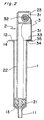
- a medical solution delivery system of the present invention which comprises a cylindrical container 1 having a port 11 at one end 13 thereof and a flanged opening 12 at the opposite end, a plunger 2 slidably arranged therein, a plunger-driving means 3 having an elasticity as a source of motive power for forcing the plunger 2 to move smoothly within the container 1 toward the port 11 thereof, and a flow control means 6 used for controlling a flow rate of a medical solution and provided with a connecting means such as a flexible connecting tube 5.
- the container 1 is a cylindrical receptacle, usually made of glass or a transparent synthetic resin such as polypropylene, polyester, poly(4-methylpentene-1), polycarbonate, or the like, with a narrow mouth serving as the port 11, the part below swelling out and then continuing straight down to the lower end having a flange 14.
- a plunger-driving means Fixed to the flange 14 is a plunger-driving means mentioned below.
- the plunger 2 used in combination with the container 1 comprises a plunger rod 22 with a cross section of a circular arc and a gasket 21 attached to a front end thereof.
- the plunger rod 22 is usually made of glass or a synthetic resin such as polypropylene, polyethylene, polyester, polycarbonate, or the like, and provided at the rear end thereof with a spring chamber 23 for holding a part of the plunger-driving means therein.
- the gasket 21 is usually made of butyl rubber or an olefin elastomer to seal an contacting area between the plunger 2 and container 1 against leakage.
- the container 1 and the plunger 2 combined therewith constitute a syringe or a plunger device for injecting or withdrawing medical solutions, like as a well-known syringe.
- the plunger-driving means 3 comprises a constant force spring 31 such as CONSTON (Trademark, Sanko Hatsujo Corporation).
- the spring 31 is fixed at one end thereof to a drum 32 and wound around the same. A part of the spring 31, wound on the drum 32, is arranged in the spring chamber 23 on the rear side of the plunger 2 and brought into contact with the rear end of the plunger 2.
- the drum 32 may be rotatably arranged in the spring chamber 23 of the plunger 2 by means of a shaft (not illustrated).
- the opposite end or free end of the spring 31 is fixed to the flange 14 of the container 1 by a fixing member such as a bolt or a pin 34. To that end, the spring 31 is bent at the opposite end thereof to form a fixing portion 33 having a hole 35 through which the pin 34 is fixed to the flange 14 of the container 1.
- the flow control means 6 is connected to the port of the container 1 by means of a connecting tube 5 to control a flow rate of the medical solution to be delivered from the container 1.
- the connecting tube 5 is separated into two parts, i.e., an upstream part and a downstream part by means of the flow control means 6.
- the upstream part of the connecting tube 5 is connected at one end thereof to the container 1 by a connector 51 and at the opposite end to one end of the flow control means 6 by a connector 52, whereas the downstream part of the connecting tube 5 is connected at one end thereof to the opposite end of the flow control means 6 by a connector 53 and at the other end to a connector 54 used for attachment of a catheter (not illustrated).
- the connecting tube 5 is unnecessarily required for the delivery system of the present invention.
- the flow control means 6 may be connected to the port 11 of the container 1.
- the flow control means 6 may have any configuration depending on the time required for administration of the medical solution or on an amount of the medical solution per unit time.
- Examples of preferred flow control means are those comprising a narrow tube provided with a very small bore as disclosed in the Japanese Patent Gazettes JP-A- S64-70069 or JP-A-H1-135359, or those comprising a pipe with a very small diameter as disclosed in JP-A- H2-11159 or JP-A- H3-140163.
- the flow control means 6 is removed first from the port 11 of the container 1 and then a medical solution to be transfused into a vein of a patient is drawn into the container 1 by pulling the plunger 2 toward the flanged opening 12 of the container 1. This may be done with ease after the wound part of the spring 31 has been taken off from the spring chamber 23 of the plunger 2. Of course, the wound part of the spring 31 is put in the spring chamber 23 of the plunger 2 after the medical solution has been drawn into the container 1. In that case, the spring 31 is deflected through a certain displacement, thereby storing energy.
- the flow control means 6 is then connected to the port 11 of the container 1 by the tube 5 at one end thereof and at the opposite end to a catheter by the connector 54.
- the connecting tube 5 is closed by a suitable closing means such as a clamp (not illustrated in the drawings).
- the closing means is removed from the tube 5 so that air in the container 1 and the tube 5 is expelled therefrom as the force is applied to the plunger 2 by the plunger-driving means 3.
- the tube 5 or the catheter is clamped again by the clamping means and then the catheter is inserted into the vein of the patient.
- the clamping means is removed form the tube 5 or the catheter so that the plunger 2 is forced again by the constant force spring 31 to move towards the front side of the container 1.
- the medical solution in the container 1 is delivered therefrom through the port 11 and injected into the vein of the patient at a fixed flow rate determined by the flow control means 6.
- the sliding movement of the plunger may be disturbed by motion of a patient.
- the plunger 2 may be disturbed its movement by the clothes.
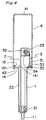
- the medical solution delivery system may be buried beneath the body of the patient then turning in bed. In order to avoid such obstructions due to the clothes or motion of the patient, it is preferred to protect the plunger and the plunger-driving means from the influence of motion of the patient with a cap 4 as shown in Fig. 3 and 4.
- FIG. 3 and 4 there is shown another embodiment of the medical solution delivery system of the present invention.
- This system further comprises a cap 4 in addition to a cylindrical container 1, a plunger 2, a plunger-driving means 3, and a flow control means 6.
- the plunger 2 is provided at the flange 14 thereof with a cylindrical portion 15 having a male screw 151 so that a cap 4 may be screwed thereon.
- the fixing portion 33 of the spring 31 is fixed to an inside wall 141 of the flange 14 surrounded by the cylindrical portion 15.
- the cap 4 may be attached to the cylindrical container 1 in various manners such as screw-mounting, or press-fitting, fusion-mounting, or bolts.
- the cap may be fixed to the flange 14 of the container 1 by a bolt (not shown). In that case, it is required to provide a hole in the closed end 41 of the cap 4 to allow the plunger 2 to be moved backward by an actuating rod which may be inserted into the cap through the hole when drawing a medical solution in the container.
- the cylindrical portion 15 is provided with an annular rib and the cap 4 is provided with a corresponding annular groove or a rib.
- Fig. 5 shows a modified form of the medical solution delivery system of Figs. 3 and 4, which comprises a solid plunger having a structure similar to that of a commercially available syringe, and a cylindrical container shown in Figs. 3 and 4.
- the wound part of the constant force spring 3 is brought into contact with the flange 24 of the plunger 2, while the free end of the constant force spring 3 is fixed to the inside wall 141 of the flange 14 surrounded by the cylindrical portion 15 of the cylinder 1.
- the cap 4 is screwed on the cylindrical portion 15 of the cylinder 1.
- the medical solution delivery system of the present invention is simple in structure and small in the number of components, thus making it possible to provide inexpensive medical solution delivery systems. Also, the system is free from elution of chemical substances as the container is of glass or a polyolefine resin.
- the constant force spring By employing the constant force spring, it is possible to provide a medical solution delivery system capable of injecting a medical solution accurately at a well-controlled flow rate. Further, it is possible to inject the medical solution into the patient safely and certainly since the plunger and plunger-driving means can be protected from external influences such as, for example, pressures caused by movement of the body of the patient.
Landscapes
- Health & Medical Sciences (AREA)
- Vascular Medicine (AREA)
- Engineering & Computer Science (AREA)
- Anesthesiology (AREA)
- Biomedical Technology (AREA)
- Heart & Thoracic Surgery (AREA)
- Hematology (AREA)
- Life Sciences & Earth Sciences (AREA)
- Animal Behavior & Ethology (AREA)
- General Health & Medical Sciences (AREA)
- Public Health (AREA)
- Veterinary Medicine (AREA)
- Infusion, Injection, And Reservoir Apparatuses (AREA)
Applications Claiming Priority (2)
| Application Number | Priority Date | Filing Date | Title |
|---|---|---|---|
| JP245488/92 | 1992-08-21 | ||
| JP4245488A JPH0663134A (ja) | 1992-08-21 | 1992-08-21 | 薬液注入具 |
Publications (1)
| Publication Number | Publication Date |
|---|---|
| EP0584714A1 true EP0584714A1 (de) | 1994-03-02 |
Family
ID=17134411
Family Applications (1)
| Application Number | Title | Priority Date | Filing Date |
|---|---|---|---|
| EP93113225A Withdrawn EP0584714A1 (de) | 1992-08-21 | 1993-08-18 | System zur Verabreichung einer medizinischen Lösung |
Country Status (2)
| Country | Link |
|---|---|
| EP (1) | EP0584714A1 (de) |
| JP (1) | JPH0663134A (de) |
Cited By (2)
| Publication number | Priority date | Publication date | Assignee | Title |
|---|---|---|---|---|
| US20090270843A1 (en) * | 2008-04-03 | 2009-10-29 | The Brigham And Women's Hospital, Inc. | Micromechanical force devices for wound healing acceleration |
| US9816903B2 (en) | 2015-02-19 | 2017-11-14 | Sartorius Stedim Biotech Gmbh | Filtration device for liquid samples |
Families Citing this family (1)
| Publication number | Priority date | Publication date | Assignee | Title |
|---|---|---|---|---|
| CN105900162B (zh) | 2014-01-21 | 2018-10-16 | 卡贝欧洲有限公司 | 注射练习装置 |
Citations (6)
| Publication number | Priority date | Publication date | Assignee | Title |
|---|---|---|---|---|
| US4298000A (en) * | 1978-11-08 | 1981-11-03 | Minnesota Mining And Manufacturing Company | Fluid dispensing device |
| US4381006A (en) * | 1980-11-10 | 1983-04-26 | Abbott Laboratories | Continuous low flow rate fluid dispenser |
| EP0223346A1 (de) * | 1985-09-25 | 1987-05-27 | Henley Investments, Inc. | Gerät zur sequentiellen Infusion von medizinischen Lösungen |
| EP0265724A2 (de) * | 1986-10-30 | 1988-05-04 | B. Braun Melsungen AG | Federaufzugsgetriebe für das Laufwerk eines Gerätes mit Durchlaufsicherung |
| US4863429A (en) * | 1987-06-30 | 1989-09-05 | Baldwin Brian E | Syringe driver/syringe/tube connecting set fluid delivery arrangement, and tube connecting sets therefor |
| EP0462508A1 (de) * | 1990-06-19 | 1991-12-27 | Toichi Ishikawa | Medizinischer Flüssigkeitsinjektor zur kontinuierlichen Transfusion |
-
1992
- 1992-08-21 JP JP4245488A patent/JPH0663134A/ja active Pending
-
1993
- 1993-08-18 EP EP93113225A patent/EP0584714A1/de not_active Withdrawn
Patent Citations (6)
| Publication number | Priority date | Publication date | Assignee | Title |
|---|---|---|---|---|
| US4298000A (en) * | 1978-11-08 | 1981-11-03 | Minnesota Mining And Manufacturing Company | Fluid dispensing device |
| US4381006A (en) * | 1980-11-10 | 1983-04-26 | Abbott Laboratories | Continuous low flow rate fluid dispenser |
| EP0223346A1 (de) * | 1985-09-25 | 1987-05-27 | Henley Investments, Inc. | Gerät zur sequentiellen Infusion von medizinischen Lösungen |
| EP0265724A2 (de) * | 1986-10-30 | 1988-05-04 | B. Braun Melsungen AG | Federaufzugsgetriebe für das Laufwerk eines Gerätes mit Durchlaufsicherung |
| US4863429A (en) * | 1987-06-30 | 1989-09-05 | Baldwin Brian E | Syringe driver/syringe/tube connecting set fluid delivery arrangement, and tube connecting sets therefor |
| EP0462508A1 (de) * | 1990-06-19 | 1991-12-27 | Toichi Ishikawa | Medizinischer Flüssigkeitsinjektor zur kontinuierlichen Transfusion |
Cited By (4)
| Publication number | Priority date | Publication date | Assignee | Title |
|---|---|---|---|---|
| US20090270843A1 (en) * | 2008-04-03 | 2009-10-29 | The Brigham And Women's Hospital, Inc. | Micromechanical force devices for wound healing acceleration |
| US9039678B2 (en) * | 2008-04-03 | 2015-05-26 | The Brigham And Women's Hospital, Inc | Micromechanical force devices for wound healing acceleration |
| US20160015592A1 (en) * | 2008-04-03 | 2016-01-21 | The Brigham And Women's Hospital | Micromechanical Force Devices for Wound Healing Acceleration |
| US9816903B2 (en) | 2015-02-19 | 2017-11-14 | Sartorius Stedim Biotech Gmbh | Filtration device for liquid samples |
Also Published As
| Publication number | Publication date |
|---|---|
| JPH0663134A (ja) | 1994-03-08 |
Similar Documents
| Publication | Publication Date | Title |
|---|---|---|
| US5380287A (en) | Medical solution delivery system | |
| US4813937A (en) | Ambulatory disposable infusion delivery system | |
| EP0737484B1 (de) | Vorgefüllte Spritze zum Einspritzen von zwei Flüssigkeiten | |
| EP1071487B1 (de) | Spritzvorrichtung | |
| CA2209956C (en) | Cannula sealing shield assembly | |
| US5356379A (en) | Disposable ambulatory infusion pump assembly | |
| US4116196A (en) | Additive adapter | |
| US4867743A (en) | Ambulatory disposable infusion delivery system | |
| EP0847770B1 (de) | Vorgefüllte Spritze | |
| US5318539A (en) | Liquid feeding apparatus utilizing capillary tubing, and syringe driver | |
| US3570484A (en) | Intravenous valve assembly | |
| US5178610A (en) | Liquid infusion device | |
| EP1455870B1 (de) | Medizinische abgabevorrichtung | |
| CN1139010A (zh) | 用于医疗注射装置的带阀连接器 | |
| NZ510060A (en) | Container for intravenous administration with container extending into insert having non-return valve, for insertion of cannula | |
| JP3275083B2 (ja) | 精密放出注入器 | |
| EP0584714A1 (de) | System zur Verabreichung einer medizinischen Lösung | |
| EP0327555B1 (de) | Einrichtung zum zuführen von medikamenten | |
| JPH10113385A (ja) | 薬液持続注入具 | |
| EP0245056A1 (de) | Ambulante Einweginfusionspumpe | |
| JP4096349B2 (ja) | 薬液持続注入器 | |
| JPH03155872A (ja) | バルーンインフューザー |
Legal Events
| Date | Code | Title | Description |
|---|---|---|---|
| PUAI | Public reference made under article 153(3) epc to a published international application that has entered the european phase |
Free format text: ORIGINAL CODE: 0009012 |
|
| AK | Designated contracting states |
Kind code of ref document: A1 Designated state(s): DE FR GB IT |
|
| STAA | Information on the status of an ep patent application or granted ep patent |
Free format text: STATUS: THE APPLICATION IS DEEMED TO BE WITHDRAWN |
|
| 18D | Application deemed to be withdrawn |
Effective date: 19940903 |