EP0582802B1 - Device for producing cables with alternating twist direction - Google Patents
Device for producing cables with alternating twist direction Download PDFInfo
- Publication number
- EP0582802B1 EP0582802B1 EP93109183A EP93109183A EP0582802B1 EP 0582802 B1 EP0582802 B1 EP 0582802B1 EP 93109183 A EP93109183 A EP 93109183A EP 93109183 A EP93109183 A EP 93109183A EP 0582802 B1 EP0582802 B1 EP 0582802B1
- Authority
- EP
- European Patent Office
- Prior art keywords
- stranding
- disc
- elements
- guide
- guide disc
- Prior art date
- Legal status (The legal status is an assumption and is not a legal conclusion. Google has not performed a legal analysis and makes no representation as to the accuracy of the status listed.)
- Expired - Lifetime
Links
Images

Classifications
-
- H—ELECTRICITY
- H01—ELECTRIC ELEMENTS
- H01B—CABLES; CONDUCTORS; INSULATORS; SELECTION OF MATERIALS FOR THEIR CONDUCTIVE, INSULATING OR DIELECTRIC PROPERTIES
- H01B13/00—Apparatus or processes specially adapted for manufacturing conductors or cables
- H01B13/02—Stranding-up
- H01B13/0235—Stranding-up by a twisting device situated between a pay-off device and a take-up device
- H01B13/0257—Stranding-up by a twisting device situated between a pay-off device and a take-up device being a perforated disc
-
- D—TEXTILES; PAPER
- D07—ROPES; CABLES OTHER THAN ELECTRIC
- D07B—ROPES OR CABLES IN GENERAL
- D07B3/00—General-purpose machines or apparatus for producing twisted ropes or cables from component strands of the same or different material
- D07B3/005—General-purpose machines or apparatus for producing twisted ropes or cables from component strands of the same or different material with alternating twist directions
Definitions
- the invention relates to a device for reversing Stranding of stranding elements, consisting of a fixed guide disc and from a distance to this arranged stranding disk rotatable about its axis, the two axially extending through holes for passage of the stranding elements, as well as from a fixed point Fixing the stranded stranding elements at a stranding point, and with at least one between the guide disc and Stranding disc arranged, thread-shaped, tensile support element, on the one hand at a distance from the guide disc and to the stranding disk, on the other hand, at least one disk-shaped Holding element is attached, which extends in the axial direction Through holes for the passage of the stranding elements has, the support element in the tensioned state between Guide disc and stranding disc is arranged.
- Stranding elements in the sense of the invention are, for example Cores of electrical and optical cables or lines of all kinds. Stranding elements can also be components of higher Be order in which several parts are already combined are. These are, for example, pairs, quads or bundles. At the stranding elements can also be threads made of plastic or bare metallic wires, for example used for the concentric protective conductor in power cables become.
- the reversing stranding in which the lay direction the stranding elements change at intervals compared to Stranding process with constant lay direction the advantage that no rotating spools (baskets) are required that are only a limited length for the to be manufactured Allow stranded goods.
- the reversing stranding offers the Possibility of continuous production with high take-off speeds.
- a known device for reversing stranding of stranding elements consisting of a fixed guide washer and from a distance from it, Stranding disk rotatable about its axis, both axially extending Through holes for the passage of the stranding elements have, as well as from a fixed point for fixing the stranded stranding elements in the stranding point, which from DE-A 22 62 705 is known, the stranding elements between the Guide washer and the stranding washer in tubes.
- These hoses are made of a plastic with low Coefficient of friction. They are meant to tangle the individual Prevent stranding elements between the two washers. In front The individual stranding elements must be put into operation of the device threaded into the hoses with some effort become.
- the hoses can easily become dirty, so that result in poorer coefficients of friction compared to the stranding elements. They also have a relatively large mass when dimensioning the device and in particular for the drive the stranding disc must be taken into account. Furthermore can not be excluded that the hoses themselves together tangle, especially when the distance between Guide washer and stranding washer is large.
- EP A1 0 031 081 is a generic device known, in which a support element, which is designed as a torsion element is non-rotatable with the guide washer and the stranding washer connected is. Between the guide disc and the stranding disk several holding elements are arranged, the are rotatably connected to the torsion element. By the Twisting the stranding disc will twist the torsion element whereby at the same time the holding elements, as well as the the stranding elements guided therein are also rotated.
- the invention has for its object the above Develop device so that with simple Structure and simple setup of the same a tangling of the Stranding elements is avoided with certainty.
- This device is very simple. It consists of the guide washer and the stranding washer and from a number of holding elements that depend on the length of the distance between Guide and stranding disc is determined. While decorating the device only need the stranding elements the through holes of all axially relatively short holding elements to be drawn.
- the holding elements can be made of one material are produced with a low coefficient of friction, so that the stranding elements during the production of a relative exposed to low friction.
- the holding elements are low in mass, so that even with a large number the same no significant additional masses during the stranding of the stranding elements are to be moved. You have a total a low rotational moment of inertia, so that the reversal times can be kept very small during stranding. At the stranding elements are a sufficiently high number of holding elements performed properly during the stranding. A tangle the same is excluded.
- Fig. 1 gives only one Schematic diagram again, in which the actual stranding line or the stranding memory is only indicated.
- the stranding disk 5 is rotatably supported by what Bearing 9 is indicated. She can reverse her Axis are rotated. For this purpose, an electric motor is used in known technology 10 used. In operation of the device, the Stranding disk 5, for example, eight revolutions in each in both directions. Apart from the zero position, these are four turns in each direction.
- the stranding point 6 is a fixed point in which the wires 1 are so be held firm because of the reversing stranding loosely connected association can not open again.
- a pair of rollers, an eyelet or a Nipples are used.
- the soul 7 can be wound on a spool or other processing stations be fed.
- the holding elements 11 are on a thread-like, tensile support member 12 attached between the guide washer 3 and stranding disk 5 along their common axis is arranged.
- the support element 12 can be made of Steel or plastic consist, for example, of aramid. It is firmly attached in the guide disc 3 and stranding disc 5, can, however, in one embodiment of the device in turn both discs freely. The latter also applies to the holding elements 11.
- the support member 12 is in a preferred embodiment between the guide washer 3 and the stranding washer 5 curious; excited.
- a clamping element can be used for this on the side of the guide disc 3 or the stranding disc 5 is attached.
- a Spring, a weight or a pneumatic cylinder can be used.
- the guide disk 3 and the stranding disk 5 preferably consist of metal
- she consist for example of polyamide or polytetrafluoroethylene. These materials have particularly good sliding properties.
- the through holes 13 of the washers 11 can be used for easier pulling of the wires 1 against the pull-off direction (Arrow 8) preferably be flared, as in Fig. 5 is shown.
- Guide disc 3, stranding disc 5 and holding elements 11 can ( 4 also a central through hole 14 to have.
- a core can pass through the central through holes 14 or basic element of any structure can be drawn around the or that the wires 1 are reversed stranded. It is also possible, a tube in the central through holes 14 to arrange, pulled through the core or base element become.
- the central support element 12 is in this embodiment the discs 3 and 5 and the holding elements 11 through replaced at least two support members 15, as it is from the 4 and 8 emerges.
- the support elements 15 are preferred Embodiment symmetrical in the circumferential direction of all Disks and holding elements 11 distributed. Also on the support elements 15, the holding elements 11 are loose and axially per se movably attached.
- a holding element 11 is arranged.
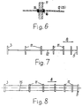
- the number of holding elements 11 depends on the properties of the processed Veins 1 and after the distance between the guide disc 3 and Stranding washer 5. The greater this distance, the more Holding washers 11 are used. Your distance from each other can be constant but also arbitrary. In the preferred embodiment is the distance between the holding elements 11 from each other with increasing distance from the guide disc 3 smaller, as can be seen from FIGS. 7 and 8. In the area of the stranding disk 5 are therefore for guiding Veins 1 more holding elements 11 available than in the area of Guide disc 3. The wires 1 are in the area with the larger angles of rotation led closer.
Landscapes
- Engineering & Computer Science (AREA)
- Manufacturing & Machinery (AREA)
- Ropes Or Cables (AREA)
- Vessels, Lead-In Wires, Accessory Apparatuses For Cathode-Ray Tubes (AREA)
- Wire Processing (AREA)
- Processes Specially Adapted For Manufacturing Cables (AREA)
- Investigating Strength Of Materials By Application Of Mechanical Stress (AREA)
Abstract
Description
Die Erfindung bezieht sich auf eine Vorrichtung zur reversierenden Verseilung von Verseilelementen, bestehend aus einer feststehenden Führungsscheibe und aus einer mit Abstand zu dieser angeordneten, um ihre Achse drehbaren Verseilscheibe, die beide axial verlaufende Durchgangslöcher zum Durchführen der Verseilelemente aufweisen, sowie aus einem Festpunkt zur Fixierung der verseilten Verseilelemente in einem Verseilpunkt, und mit mindestens einem zwischen Führungsscheibe und Verseilscheibe angeordneten, fadenförmigen, zugfesten Tragelement, an dem mit Abstand zur Führungsscheibe einerseits und zur Verseilscheibe andererseits mindestens ein scheibenförmiges Halteelement angebracht ist, das in axialer Richtung verlaufende Durchgangslöcher zur Durchführung der Verseilelemente aufweist, wobei das Tragelement in gespanntem Zustand zwischen Führungsscheibe und Verseilscheibe angeordnet ist.The invention relates to a device for reversing Stranding of stranding elements, consisting of a fixed guide disc and from a distance to this arranged stranding disk rotatable about its axis, the two axially extending through holes for passage of the stranding elements, as well as from a fixed point Fixing the stranded stranding elements at a stranding point, and with at least one between the guide disc and Stranding disc arranged, thread-shaped, tensile support element, on the one hand at a distance from the guide disc and to the stranding disk, on the other hand, at least one disk-shaped Holding element is attached, which extends in the axial direction Through holes for the passage of the stranding elements has, the support element in the tensioned state between Guide disc and stranding disc is arranged.
"Verseilelemente" im Sinne der Erfindung sind beispielsweise Adern von elektrischen und optischen Kabeln bzw. Leitungen aller Art. Verseilelemente können aber auch Bauteile höherer Ordnung sein, in denen schon mehrere Teile zusammengefaßt sind. Das sind beispielsweise Paare, Vierer oder Bündel. Bei den Verseilelementen kann es sich auch um Fäden aus Kunststoff oder um blanke metallische Drähte handeln, die beispielsweise für den konzentrischen Schutzleiter bei Starkstromkabeln eingesetzt werden."Stranding elements" in the sense of the invention are, for example Cores of electrical and optical cables or lines of all kinds. Stranding elements can also be components of higher Be order in which several parts are already combined are. These are, for example, pairs, quads or bundles. At the stranding elements can also be threads made of plastic or bare metallic wires, for example used for the concentric protective conductor in power cables become.
Die reversierende Verseilung, bei welcher die Schlagrichtung der Verseilelemente in Abständen wechselt, hat gegenüber dem Verseilverfahren mit gleichbleibender Schlagrichtung den Vorteil, daß keine rotierenden Spulenabläufe (Körbe) benötigt werden, die eine nur begrenzte Länge für das herzustellende Verseilgut zulassen. Die reversierende Verseilung bietet die Möglichkeit einer kontinuierlichen Fertigung mit hohen Abzugsgeschwindigkeiten. The reversing stranding, in which the lay direction the stranding elements change at intervals compared to Stranding process with constant lay direction the advantage that no rotating spools (baskets) are required that are only a limited length for the to be manufactured Allow stranded goods. The reversing stranding offers the Possibility of continuous production with high take-off speeds.
Bei einer bekannten Vorrichtung zur reversierenden Verseilung von Verseilelementen, bestehend aus einer feststehenden Führungsscheibe und aus einer mit Abstand zu dieser angeordneten, um ihre Achse drehbaren Verseilscheibe, die beide axial verlaufende Durchgangslöcher zur Durchführung der Verseilerelemente aufweisen, sowie aus einem Festpunkt zur Fixierung der verseilten Verseilelemente im Verseilpunkt, die aus der DE-A 22 62 705 bekannt ist, werden die Verseilelemente zwischen der Führungsscheibe und der Verseilscheibe in Schläuchen geführt. Diese Schläuche bestehen aus einem Kunststoff mit niedrigem Reibungskoeffizienten. Sie sollen ein Verheddern der einzelnen Verseilelemente zwischen den beiden Scheiben verhindern. Vor Inbetriebnahme der Vorrichtung müssen die einzelnen Verseilelemente mit einigem Aufwand in die Schläuche eingefädelt werden. Die Schläuche können leicht verschmutzen, so daß sich gegenüber den Verseilelementen schlechtere Reibwerte ergeben. Sie haben außerdem eine relativ große Masse, die bei der Dimensionierung der Vorrichtung und insbesondere für den Antrieb der Verseilscheibe zu berücksichtigen ist. Weiterhin kann nicht ausgeschlossen werden, daß die Schläuche selbst miteinander verheddern, insbesondere dann, wenn der Abstand zwischen Führungsscheibe und Verseilscheibe groß ist.In a known device for reversing stranding of stranding elements, consisting of a fixed guide washer and from a distance from it, Stranding disk rotatable about its axis, both axially extending Through holes for the passage of the stranding elements have, as well as from a fixed point for fixing the stranded stranding elements in the stranding point, which from DE-A 22 62 705 is known, the stranding elements between the Guide washer and the stranding washer in tubes. These hoses are made of a plastic with low Coefficient of friction. They are meant to tangle the individual Prevent stranding elements between the two washers. In front The individual stranding elements must be put into operation of the device threaded into the hoses with some effort become. The hoses can easily become dirty, so that result in poorer coefficients of friction compared to the stranding elements. They also have a relatively large mass when dimensioning the device and in particular for the drive the stranding disc must be taken into account. Furthermore can not be excluded that the hoses themselves together tangle, especially when the distance between Guide washer and stranding washer is large.
Aus der EP A1 0 031 081 ist eine gattungsgemäße Vorrichtung bekannt, bei der ein Tragelement, das als Torsionselement ausgebildet ist, drehfest mit der Führungsscheibe und der Verseilscheibe verbunden ist. Zwischen der Führungsscheibe und der Verseilscheibe sind mehrere Haltelemente angeordnet, die drehfest mit dem Torsionselement verbunden sind. Durch das Verdrehen der Verseilscheibe wird das Torsionselement verdreht, wodurch gleichzeitig auch die Haltelemente, sowie die darin geführten Verseilelemente mitgedreht werden.EP A1 0 031 081 is a generic device known, in which a support element, which is designed as a torsion element is non-rotatable with the guide washer and the stranding washer connected is. Between the guide disc and the stranding disk several holding elements are arranged, the are rotatably connected to the torsion element. By the Twisting the stranding disc will twist the torsion element whereby at the same time the holding elements, as well as the the stranding elements guided therein are also rotated.
Der Erfindung liegt die Aufgabe zugrunde, die eingangs beschriebene Vorrichtung so weiterzubilden, daß bei einfachem Aufbau und einfacher Einrichtung derselben ein Verheddern der Verseilelemente mit Sicherheit vermieden ist.The invention has for its object the above Develop device so that with simple Structure and simple setup of the same a tangling of the Stranding elements is avoided with certainty.
Diese Aufgabe wird gemäß der Erfindung dadurch gelöst, daß das scheibenförmige Halteelement lose, aber in axialer Richtung fixiert an dem Tragelement angebracht ist.This object is achieved according to the invention in that the disc-shaped holding element loose, but in the axial direction is fixedly attached to the support element.
Diese Vorrichtung ist sehr einfach aufgebaut. Sie besteht aus der Führungsscheibe und der Verseilscheibe und aus einer Anzahl von Halteelementen, die von der Länge des Abstands zwischen Führungs- und Verseilscheibe bestimmt wird. Beim Einrichten der Vorrichtung brauchen die Verseilelemente nur durch die Durchgangslöcher aller axial relativ kurzen Halteelemente gezogen zu werden. Die Halteelemente können aus einem Werkstoff mit niedrigem Reibungskoeffizienten hergestellt werden, so daß die Verseilelemente während der Fertigung einer verhältnismäßig geringen Reibung ausgesetzt sind. Die Halteelemente sind massearm, so daß selbst bei einer größeren Anzahl derselben keine wesentlichen Zusatzmassen während der Verseilung der Verseilelemente zu bewegen sind. Sie haben insgesamt ein geringes Rotationsträgheitsmoment, so daß die Umkehrzeiten bei der Verseilung sehr klein gehalten werden können. Bei ausreichend hoher Anzahl von Halteelementen sind die Verseilelemente während der Verseilung einwandfrei geführt. Ein Verheddern derselben ist ausgeschlossen.This device is very simple. it consists of the guide washer and the stranding washer and from a number of holding elements that depend on the length of the distance between Guide and stranding disc is determined. While decorating the device only need the stranding elements the through holes of all axially relatively short holding elements to be drawn. The holding elements can be made of one material are produced with a low coefficient of friction, so that the stranding elements during the production of a relative exposed to low friction. The holding elements are low in mass, so that even with a large number the same no significant additional masses during the stranding of the stranding elements are to be moved. You have a total a low rotational moment of inertia, so that the reversal times can be kept very small during stranding. At the stranding elements are a sufficiently high number of holding elements performed properly during the stranding. A tangle the same is excluded.
Weitere vorteilhafte Ausgestaltungen der Erfindung gehen aus den Unteransprüchen hervor.Further advantageous embodiments of the invention are based the subclaims.
Ausführungsbeispiele des Erfindungsgegenstandes sind in den Zeichnungen dargestellt.Embodiments of the subject matter of the invention are in the Drawings shown.
Es zeigt:
Die Erfindung wird im folgenden für eine Vorrichtung erläutert, mit der drei Verseilelemente verseilt werden können. Bei entsprechender Gestaltung von Führungs- und Verseilscheibe sowie Halteelementen können auch zwei oder mehr als drei Verseilelemente verarbeitet werden. Fig. 1 gibt dabei nur eine Prinzipdarstellung wieder, in der die eigentliche Verseilstrecke bzw. der Verseilspeicher nur angedeutet ist.The invention is explained below for a device with which three stranding elements can be stranded. At appropriate design of guide and stranding washer and holding elements can also be two or more than three stranding elements are processed. Fig. 1 gives only one Schematic diagram again, in which the actual stranding line or the stranding memory is only indicated.
Gemäß Fig. 1 werden drei Verseilelemente 1 - im folgenden
stellvertretend für alle anderen Möglichkeiten als "Adern 111
bezeichnet - von Spulen 2 abgezogen und einer Führungsscheibe
3 zugeführt. Nach Durchlaufen einer Verseilstrecke 4, deren
genauerer Aufbau aus den Fig. 2, 7 und 8 hervorgeht, gelangen
die Adern 1 zu einer Verseilscheibe 5. Sie werden in einem
Verseilpunkt 6 reversierend zu einer Seele 7 miteinander verseilt,
die in Richtung des Pfeiles 8 abgezogen wird.1, three stranding elements 1 - in the following
representative of all options other than "wires 111
designated - deducted from coils 2 and a
Die Verseilscheibe 5 ist drehbar gelagert, was durch eine
Lagerstelle 9 angedeutet ist. Sie kann reversierend um ihre
Achse gedreht werden. Dazu wird in bekannter Technik ein Elektromotor
10 verwendet. Im Betrieb der Vorrichtung führt die
Verseilscheibe 5 beispielsweise jeweils acht Umdrehungen in
beiden Drehrichtungen aus. Von der Nullage ausgesehen sind das
in jeder Drehrichtung vier Umdrehungen.The
Der Verseilpunkt 6 ist ein Fixpunkt, in dem die Adern 1 so
fest gehalten werden, daß ihr wegen der reversierenden Verseilung
an sich lockerer Verbund nicht wieder aufgehen kann.
Hier kann beispielsweise ein Rollenpaar, eine Öse oder ein
Nippel eingesetzt werden. Hinter dem Verseilpunkt 6 wird eine
Halterung auf die Seele 7 aufgebracht. Dazu kann ein Band
aufgewickelt oder ein Mantel aufgespritzt werden. Die Seele 7
kann auf eine Spule aufgewickelt oder weiteren Bearbeitungsstationen
zugeführt werden.The
In der Verseilstrecke 4 sind gemäß Fig. 2 zwei als Scheiben
dargestellte Halteelemente 11 angebracht, und zwar mit Abstand
zueinander sowie zu der Führungsscheibe 3 und der Verseilscheibe
5. Die Halteelemente 11 sind an einem fadenförmigen,
zugfesten Tragelement 12 befestigt, das zwischen Führungsscheibe
3 und Verseilscheibe 5 entlang deren gemeinsamer Achse
angeordnet ist.2 are two as disks in
Führungsscheibe 3, Verseilscheibe 5 und Halteelemente 11 haben
im dargestellten Ausführungsbeispiel jeweils drei in axialer
Richtung verlaufende Durchgangslöcher 13, durch welche die
Adern 1 hindurchgezogen werden. Das Tragelement 12 kann aus
Stahl oder Kunststoff bestehen, beispielsweise aus Aramid. Es
ist fest in Führungsscheibe 3 und Verseilscheibe 5 angebracht,
kann sich aber in einer Ausführungsform der Vorrichtung in
beiden Scheiben frei drehen. Letzteres gilt auch für die Halteelemente
11. Das Tragelement 12 ist in bevorzugter Ausführungsform
zwischen Führungsscheibe 3 und Verseilscheibe 5
gespannt. Dazu kann ein Spannelement eingesetzt werden, das
auf der Seite der Führungsscheibe 3 oder der Verseilscheibe 5
angebracht wird. Als Spannelement können beispielsweise eine
Feder, ein Gewicht oder ein Pneumatikzylinder eingesetzt werden.Have
Während die Führungsscheibe 3 und die Verseilscheibe 5 vorzugsweise
aus Metall bestehen, wird für die Halteelemente 11
leichteres Material, insbesondere Kunststoff, bevorzugt. Sie
bestehen beispielsweise aus Polyamid oder Polytetrafluorethylen.
Diese Materialien haben besonders gute Gleiteigenschaften.
Die Durchgangslöcher 13 der Haltescheiben 11 können zum
leichteren Durchziehen der Adern 1 entgegen der Abzugsrichtung
(Pfeil 8) vorzugsweise konisch aufgeweitet sein, so wie es in
Fig. 5 dargestellt ist. While the
Führungsscheibe 3, Verseilscheibe 5 und Halteelemte 11 können (
gemäß Fig. 4 jeweils auch ein zentrales Durchgangsloch 14
haben. Durch die zentralen Durchgangslöcher 14 kann ein Kern
oder Grundelement beliebigen Aufbaus gezogen werden, um den
bzw. das die Adern 1 reversierend herumverseilt werden. Es ist
auch möglich, in den zentralen Durchgangslöchern 14 ein Rohr
anzuordnen, durch das Kern oder Grundelement hindurchgezogen
werden. Das zentrale Tragelement 12 wird bei dieser Ausführungsform
der Scheiben 3 und 5 und der Halteelemente 11 durch
mindestens zwei Tragelemente 15 ersetzt, so wie es aus den
Fig. 4 und 8 hervorgeht. Die Tragelemente 15 sind in bevorzugter
Ausführungsform symmetrisch in Umfangsrichtung aller
Scheiben und Halteelemente 11 verteilt. Auch auf den Tragelementen
15 sind die Halteelemente 11 lose und an sich axial
beweglich angebracht. Die axiale Position der Halteelemente 11
auf den Tragelementen 12 bzw. 15 wird entsprechend Fig. 6
durch Klemmen 16 fixiert, die auf beiden Seiten der Halteelemente
11 fest auf dem jeweiligen Tragelement 12 bzw. 15
angebracht sind. Wenn zwei oder mehr Tragelemente 15 vorhanden
sind, reicht es aus, wenn die Klemmen 16 nur auf einem dieser
Tragelemente angebracht werden.
Zwischen Führungsscheibe 3 und Verseilscheibe 5 ist mindestens
ein Halteelement 11 angeordnet. Die Anzahl der Halteelemente
11 richtet sich nach den Eigenschaften der zu verarbeitenden
Adern 1 und nach der Entfernung zwischen Führungsscheibe 3 und
Verseilscheibe 5. Je größer diese Entfernung ist, desto mehr
Haltescheiben 11 werden eingesetzt. Ihr jeweiliger Abstand
voneinander kann gleichbleibend aber auch beliebig sein. In
bevorzugter Ausführungsform wird der Abstand der Halteelemente
11 voneinander mit zunehmender Entfernung von der Führungsscheibe
3 kleiner, so wie es aus den Fig. 7 und 8 hervorgeht.
Im Bereich der Verseilscheibe 5 sind also zur Führung der
Adern 1 mehr Halteelemente 11 vorhanden als im Bereich der
Führungsscheibe 3. Die Adern 1 sind dadurch in dem Bereich mit
den größeren Drehwinkeln enger geführt.At least between the
Claims (4)
- Device for the reversing stranding of stranding elements (1), consisting of a fixed guide disc (3) and of a stranding disc (5), rotatable about its axis and disposed at a spacing from the guide disc, said discs both having through holes (13) running axially and through which the stranding elements (1) are led, as well as of a fixed point for fixing the stranded stranding elements (1) in a stranding point (6), and with at least one threadlike supporting member (12, 15) having tensile strength and disposed between guide disc (3) and stranding disc (5) and to which there is attached at a spacing from the guide disc (3) on the one hand and from the stranding disc (5) on the other hand at least one disc-shaped retaining member (11) which has through holes (13) running in an axial direction and through which the stranding elements (1) are led, the supporting member (12, 15) being disposed in a tensioned state between guide disc (3) and stranding disc (5), characterised in that the disc-shaped retaining member (11) is loosely attached to the supporting member (12, 15) but fixed in an axial direction.
- Device according to claim 1, characterised in that two or more supporting members (12, 15) are attached between guide disc (3) and stranding disc (5) and are distributed symmetrically in the peripheral direction of the discs (3, 5) and of the retaining member (11).
- Device according to one of claims 1 or 2, characterised in that the guide disc (3) and the stranding disc (5) as well as all the retaining members (11) have a central through hole (14).
- Device according to one of claims 1 to 3, characterised in that, where more than three retaining members (11) are used, their mutual spacing decreases with increasing distance from the guide disc (3).
Applications Claiming Priority (4)
| Application Number | Priority Date | Filing Date | Title |
|---|---|---|---|
| DE19924226514 DE4226514A1 (en) | 1992-08-11 | 1992-08-11 | Guide for making alternating twist cable |
| DE4226514 | 1992-08-11 | ||
| DE4317496 | 1993-05-26 | ||
| DE19934317496 DE4317496A1 (en) | 1993-05-26 | 1993-05-26 | Apparatus for the reversing stranding of stranding elements |
Publications (2)
| Publication Number | Publication Date |
|---|---|
| EP0582802A1 EP0582802A1 (en) | 1994-02-16 |
| EP0582802B1 true EP0582802B1 (en) | 1999-03-10 |
Family
ID=25917409
Family Applications (1)
| Application Number | Title | Priority Date | Filing Date |
|---|---|---|---|
| EP93109183A Expired - Lifetime EP0582802B1 (en) | 1992-08-11 | 1993-06-08 | Device for producing cables with alternating twist direction |
Country Status (6)
| Country | Link |
|---|---|
| EP (1) | EP0582802B1 (en) |
| AT (1) | ATE177485T1 (en) |
| CA (1) | CA2103746C (en) |
| DE (1) | DE59309423D1 (en) |
| ES (1) | ES2131084T3 (en) |
| FI (1) | FI100893B (en) |
Families Citing this family (7)
| Publication number | Priority date | Publication date | Assignee | Title |
|---|---|---|---|---|
| AT401533B (en) * | 1994-06-28 | 1996-09-25 | Bergsmann Ludwig | DEVICE FOR MANUFACTURING A CABLE WIRING WITH ALTERNATING PUNCHING DIRECTION |
| AT478U1 (en) * | 1994-10-25 | 1995-11-27 | Schwechater Kabelwerke | DEVICE FOR FEEDING ROPE ELEMENTS TO THE ROPE HEAD OF AN INTERCHANGEABLE STRING MACHINE |
| AT402305B (en) * | 1995-06-06 | 1997-04-25 | Seibert Gerhard Ing | DEVICE FOR PRODUCING A CABLE WIRING |
| AT404265B (en) * | 1995-06-12 | 1998-10-27 | Gerhard Ing Seibert | Method for the production of cable stranding |
| FR2737337B1 (en) * | 1995-07-26 | 1997-09-19 | Kertscher Sa E | WIRING STATION FOR ALTERNATE OR SZ TYPE WIRING MACHINE |
| EP0932165B1 (en) * | 1998-01-23 | 2007-05-16 | Rosendahl Maschinen GmbH | Cable-twist manufacturing device |
| AT407266B (en) * | 1999-03-24 | 2001-02-26 | Schwechater Kabelwerke | Device for feeding rope elements to the stranding head of a reverse-lay stranding machine |
Family Cites Families (3)
| Publication number | Priority date | Publication date | Assignee | Title |
|---|---|---|---|---|
| NL6716538A (en) * | 1967-12-05 | 1969-06-09 | ||
| AU3212571A (en) * | 1970-08-13 | 1973-02-15 | Dunlop Australia Limited | Improvements in reinforced articles |
| CA1113806A (en) * | 1979-12-19 | 1981-12-08 | Bretislav P. Zuber | Apparatus for stranding wire |
-
1993
- 1993-06-08 AT AT93109183T patent/ATE177485T1/en not_active IP Right Cessation
- 1993-06-08 DE DE59309423T patent/DE59309423D1/en not_active Expired - Fee Related
- 1993-06-08 ES ES93109183T patent/ES2131084T3/en not_active Expired - Lifetime
- 1993-06-08 EP EP93109183A patent/EP0582802B1/en not_active Expired - Lifetime
- 1993-08-10 CA CA002103746A patent/CA2103746C/en not_active Expired - Fee Related
- 1993-08-10 FI FI933530A patent/FI100893B/en not_active IP Right Cessation
Also Published As
| Publication number | Publication date |
|---|---|
| CA2103746A1 (en) | 1994-02-12 |
| FI933530A (en) | 1994-02-12 |
| FI933530A0 (en) | 1993-08-10 |
| EP0582802A1 (en) | 1994-02-16 |
| CA2103746C (en) | 1997-10-21 |
| FI100893B (en) | 1998-03-13 |
| DE59309423D1 (en) | 1999-04-15 |
| ATE177485T1 (en) | 1999-03-15 |
| ES2131084T3 (en) | 1999-07-16 |
Similar Documents
| Publication | Publication Date | Title |
|---|---|---|
| DE3779755T2 (en) | ALTERNATIVE REVERSE TWIST AND ALTERNATIVE REVERSE TWIST. | |
| DE2330409C2 (en) | Double twist stranding machine | |
| EP0582802B1 (en) | Device for producing cables with alternating twist direction | |
| DE69203179T2 (en) | Reversing stranding device. | |
| DE69604543T2 (en) | Stranding system for reversing or SZ stranding machine | |
| DE2813966C2 (en) | ||
| DE1134130B (en) | Method for layer stranding of telecommunication cable stranding elements | |
| DE3109756C2 (en) | Vertical stranding machine | |
| EP0663101B1 (en) | Process and arrangement for stranding elongated elements | |
| DE1105015B (en) | Machine for the production of stranding elements for the construction of electrical cables | |
| DE2615275A1 (en) | Stranding machine for making cables - has guiding disc and perforated disc with perforated ring around it, driven by motor | |
| DE3023257C2 (en) | ||
| DE3013933C2 (en) | Device for layer-by-layer SZ stranding of stranding elements of electrical cables | |
| DE19501001C2 (en) | Device for reversing stranding of stranding elements | |
| DE4226514A1 (en) | Guide for making alternating twist cable | |
| DE1811176A1 (en) | Cable winding machine | |
| DE69203180T2 (en) | Reversing stranding device. | |
| DE2123852C3 (en) | Device for stranding stranding elements for telecommunication cables | |
| DE2412199C2 (en) | Method for stranding electrical cables or lines in sections with alternating twist direction or twist length | |
| DE1510121C3 (en) | Wing twisting machine for the production of a wire rope consisting of steel wires with a small cross-section | |
| DE1785448A1 (en) | Multiple twist spindle | |
| DE4317496A1 (en) | Apparatus for the reversing stranding of stranding elements | |
| DE2213917C3 (en) | Device on a winding machine for reinforcing winding ends | |
| EP3775367B1 (en) | Stranding machine | |
| DE4001837C2 (en) |
Legal Events
| Date | Code | Title | Description |
|---|---|---|---|
| PUAI | Public reference made under article 153(3) epc to a published international application that has entered the european phase |
Free format text: ORIGINAL CODE: 0009012 |
|
| 17P | Request for examination filed |
Effective date: 19931206 |
|
| AK | Designated contracting states |
Kind code of ref document: A1 Designated state(s): AT CH DE ES FR GB IT LI SE |
|
| 17Q | First examination report despatched |
Effective date: 19960429 |
|
| RAP1 | Party data changed (applicant data changed or rights of an application transferred) |
Owner name: FRISCH GMBH |
|
| GRAG | Despatch of communication of intention to grant |
Free format text: ORIGINAL CODE: EPIDOS AGRA |
|
| GRAG | Despatch of communication of intention to grant |
Free format text: ORIGINAL CODE: EPIDOS AGRA |
|
| GRAH | Despatch of communication of intention to grant a patent |
Free format text: ORIGINAL CODE: EPIDOS IGRA |
|
| GRAH | Despatch of communication of intention to grant a patent |
Free format text: ORIGINAL CODE: EPIDOS IGRA |
|
| GRAA | (expected) grant |
Free format text: ORIGINAL CODE: 0009210 |
|
| AK | Designated contracting states |
Kind code of ref document: B1 Designated state(s): AT CH DE ES FR GB IT LI SE |
|
| REF | Corresponds to: |
Ref document number: 177485 Country of ref document: AT Date of ref document: 19990315 Kind code of ref document: T |
|
| REG | Reference to a national code |
Ref country code: CH Ref legal event code: EP |
|
| REF | Corresponds to: |
Ref document number: 59309423 Country of ref document: DE Date of ref document: 19990415 |
|
| ET | Fr: translation filed | ||
| REG | Reference to a national code |
Ref country code: CH Ref legal event code: NV Representative=s name: RIEDERER HASLER & PARTNER PATENTANWAELTE AG |
|
| REG | Reference to a national code |
Ref country code: ES Ref legal event code: FG2A Ref document number: 2131084 Country of ref document: ES Kind code of ref document: T3 |
|
| GBV | Gb: ep patent (uk) treated as always having been void in accordance with gb section 77(7)/1977 [no translation filed] |
Effective date: 19990310 |
|
| REG | Reference to a national code |
Ref country code: GB Ref legal event code: 710B Free format text: REQUEST HAS BEEN FILED UNDER RULE 110(4) OF THE RULES 1995 TO EXTEND THE PERIOD FOR FILING A TRANSLATION OF THE SPECIFICATION. THIS PATENT WAS ANNOUNCED AS VOID IN THE PATENT AND DESIGNS JOURNAL 5757 DATED 08.09.1999. |
|
| GBT | Gb: translation of ep patent filed (gb section 77(6)(a)/1977) |
Effective date: 19991122 |
|
| REG | Reference to a national code |
Ref country code: GB Ref legal event code: 710B Free format text: FOLLOWING A REQUEST UNDER RULE 110(4) OF THE RULES 1995 TO EXTEND THE PERIOD FOR FILING A TRANSLATION OF THE SPECIFICATION, A TRANSLATION HAS NOW BEEN FILED IN ACCORDANCE WITH SECTION 77(6)(A). |
|
| PLBE | No opposition filed within time limit |
Free format text: ORIGINAL CODE: 0009261 |
|
| STAA | Information on the status of an ep patent application or granted ep patent |
Free format text: STATUS: NO OPPOSITION FILED WITHIN TIME LIMIT |
|
| 26N | No opposition filed | ||
| REG | Reference to a national code |
Ref country code: GB Ref legal event code: IF02 |
|
| PGFP | Annual fee paid to national office [announced via postgrant information from national office to epo] |
Ref country code: GB Payment date: 20030604 Year of fee payment: 11 |
|
| PGFP | Annual fee paid to national office [announced via postgrant information from national office to epo] |
Ref country code: FR Payment date: 20030605 Year of fee payment: 11 |
|
| PGFP | Annual fee paid to national office [announced via postgrant information from national office to epo] |
Ref country code: ES Payment date: 20030606 Year of fee payment: 11 |
|
| PGFP | Annual fee paid to national office [announced via postgrant information from national office to epo] |
Ref country code: DE Payment date: 20030611 Year of fee payment: 11 |
|
| PGFP | Annual fee paid to national office [announced via postgrant information from national office to epo] |
Ref country code: AT Payment date: 20030618 Year of fee payment: 11 |
|
| PGFP | Annual fee paid to national office [announced via postgrant information from national office to epo] |
Ref country code: SE Payment date: 20030626 Year of fee payment: 11 |
|
| PGFP | Annual fee paid to national office [announced via postgrant information from national office to epo] |
Ref country code: CH Payment date: 20030702 Year of fee payment: 11 |
|
| PG25 | Lapsed in a contracting state [announced via postgrant information from national office to epo] |
Ref country code: GB Free format text: LAPSE BECAUSE OF NON-PAYMENT OF DUE FEES Effective date: 20040608 Ref country code: AT Free format text: LAPSE BECAUSE OF NON-PAYMENT OF DUE FEES Effective date: 20040608 |
|
| PG25 | Lapsed in a contracting state [announced via postgrant information from national office to epo] |
Ref country code: SE Free format text: LAPSE BECAUSE OF NON-PAYMENT OF DUE FEES Effective date: 20040609 Ref country code: ES Free format text: LAPSE BECAUSE OF NON-PAYMENT OF DUE FEES Effective date: 20040609 |
|
| PG25 | Lapsed in a contracting state [announced via postgrant information from national office to epo] |
Ref country code: LI Free format text: LAPSE BECAUSE OF NON-PAYMENT OF DUE FEES Effective date: 20040630 Ref country code: CH Free format text: LAPSE BECAUSE OF NON-PAYMENT OF DUE FEES Effective date: 20040630 |
|
| PG25 | Lapsed in a contracting state [announced via postgrant information from national office to epo] |
Ref country code: DE Free format text: LAPSE BECAUSE OF NON-PAYMENT OF DUE FEES Effective date: 20050101 |
|
| GBPC | Gb: european patent ceased through non-payment of renewal fee |
Effective date: 20040608 |
|
| EUG | Se: european patent has lapsed | ||
| EUG | Se: european patent has lapsed | ||
| REG | Reference to a national code |
Ref country code: CH Ref legal event code: PL |
|
| PG25 | Lapsed in a contracting state [announced via postgrant information from national office to epo] |
Ref country code: FR Free format text: LAPSE BECAUSE OF NON-PAYMENT OF DUE FEES Effective date: 20050228 |
|
| REG | Reference to a national code |
Ref country code: FR Ref legal event code: ST |
|
| PG25 | Lapsed in a contracting state [announced via postgrant information from national office to epo] |
Ref country code: IT Free format text: LAPSE BECAUSE OF NON-PAYMENT OF DUE FEES Effective date: 20050608 |
|
| REG | Reference to a national code |
Ref country code: ES Ref legal event code: FD2A Effective date: 20040609 |