EP0582405A1 - Method of drawing an optical fibre and fibre produced thereby - Google Patents
Method of drawing an optical fibre and fibre produced thereby Download PDFInfo
- Publication number
- EP0582405A1 EP0582405A1 EP93305780A EP93305780A EP0582405A1 EP 0582405 A1 EP0582405 A1 EP 0582405A1 EP 93305780 A EP93305780 A EP 93305780A EP 93305780 A EP93305780 A EP 93305780A EP 0582405 A1 EP0582405 A1 EP 0582405A1
- Authority
- EP
- European Patent Office
- Prior art keywords
- fiber
- spin
- torque
- impressed
- optical fiber
- Prior art date
- Legal status (The legal status is an assumption and is not a legal conclusion. Google has not performed a legal analysis and makes no representation as to the accuracy of the status listed.)
- Granted
Links
Images


Classifications
-
- G—PHYSICS
- G02—OPTICS
- G02B—OPTICAL ELEMENTS, SYSTEMS OR APPARATUS
- G02B6/00—Light guides; Structural details of arrangements comprising light guides and other optical elements, e.g. couplings
- G02B6/02—Optical fibres with cladding with or without a coating
- G02B6/02214—Optical fibres with cladding with or without a coating tailored to obtain the desired dispersion, e.g. dispersion shifted, dispersion flattened
- G02B6/02285—Characterised by the polarisation mode dispersion [PMD] properties, e.g. for minimising PMD
-
- C—CHEMISTRY; METALLURGY
- C03—GLASS; MINERAL OR SLAG WOOL
- C03B—MANUFACTURE, SHAPING, OR SUPPLEMENTARY PROCESSES
- C03B37/00—Manufacture or treatment of flakes, fibres, or filaments from softened glass, minerals, or slags
- C03B37/01—Manufacture of glass fibres or filaments
- C03B37/02—Manufacture of glass fibres or filaments by drawing or extruding, e.g. direct drawing of molten glass from nozzles; Cooling fins therefor
- C03B37/025—Manufacture of glass fibres or filaments by drawing or extruding, e.g. direct drawing of molten glass from nozzles; Cooling fins therefor from reheated softened tubes, rods, fibres or filaments, e.g. drawing fibres from preforms
- C03B37/027—Fibres composed of different sorts of glass, e.g. glass optical fibres
-
- C—CHEMISTRY; METALLURGY
- C03—GLASS; MINERAL OR SLAG WOOL
- C03B—MANUFACTURE, SHAPING, OR SUPPLEMENTARY PROCESSES
- C03B37/00—Manufacture or treatment of flakes, fibres, or filaments from softened glass, minerals, or slags
- C03B37/01—Manufacture of glass fibres or filaments
- C03B37/02—Manufacture of glass fibres or filaments by drawing or extruding, e.g. direct drawing of molten glass from nozzles; Cooling fins therefor
- C03B37/025—Manufacture of glass fibres or filaments by drawing or extruding, e.g. direct drawing of molten glass from nozzles; Cooling fins therefor from reheated softened tubes, rods, fibres or filaments, e.g. drawing fibres from preforms
- C03B37/027—Fibres composed of different sorts of glass, e.g. glass optical fibres
- C03B37/02745—Fibres having rotational spin around the central longitudinal axis, e.g. alternating +/- spin to reduce polarisation mode dispersion
-
- C—CHEMISTRY; METALLURGY
- C03—GLASS; MINERAL OR SLAG WOOL
- C03B—MANUFACTURE, SHAPING, OR SUPPLEMENTARY PROCESSES
- C03B37/00—Manufacture or treatment of flakes, fibres, or filaments from softened glass, minerals, or slags
- C03B37/01—Manufacture of glass fibres or filaments
- C03B37/02—Manufacture of glass fibres or filaments by drawing or extruding, e.g. direct drawing of molten glass from nozzles; Cooling fins therefor
- C03B37/03—Drawing means, e.g. drawing drums ; Traction or tensioning devices
-
- C—CHEMISTRY; METALLURGY
- C03—GLASS; MINERAL OR SLAG WOOL
- C03B—MANUFACTURE, SHAPING, OR SUPPLEMENTARY PROCESSES
- C03B37/00—Manufacture or treatment of flakes, fibres, or filaments from softened glass, minerals, or slags
- C03B37/01—Manufacture of glass fibres or filaments
- C03B37/02—Manufacture of glass fibres or filaments by drawing or extruding, e.g. direct drawing of molten glass from nozzles; Cooling fins therefor
- C03B37/03—Drawing means, e.g. drawing drums ; Traction or tensioning devices
- C03B37/032—Drawing means, e.g. drawing drums ; Traction or tensioning devices for glass optical fibres
-
- G—PHYSICS
- G02—OPTICS
- G02B—OPTICAL ELEMENTS, SYSTEMS OR APPARATUS
- G02B6/00—Light guides; Structural details of arrangements comprising light guides and other optical elements, e.g. couplings
- G02B6/10—Light guides; Structural details of arrangements comprising light guides and other optical elements, e.g. couplings of the optical waveguide type
- G02B6/105—Light guides; Structural details of arrangements comprising light guides and other optical elements, e.g. couplings of the optical waveguide type having optical polarisation effects
-
- C—CHEMISTRY; METALLURGY
- C03—GLASS; MINERAL OR SLAG WOOL
- C03B—MANUFACTURE, SHAPING, OR SUPPLEMENTARY PROCESSES
- C03B2203/00—Fibre product details, e.g. structure, shape
- C03B2203/02—External structure or shape details
- C03B2203/06—Axial perturbations, e.g. twist, by torsion, undulating, crimped
-
- C—CHEMISTRY; METALLURGY
- C03—GLASS; MINERAL OR SLAG WOOL
- C03B—MANUFACTURE, SHAPING, OR SUPPLEMENTARY PROCESSES
- C03B2203/00—Fibre product details, e.g. structure, shape
- C03B2203/10—Internal structure or shape details
- C03B2203/18—Axial perturbations, e.g. in refractive index or composition
- C03B2203/19—Alternating positive/negative spins or twists
-
- C—CHEMISTRY; METALLURGY
- C03—GLASS; MINERAL OR SLAG WOOL
- C03B—MANUFACTURE, SHAPING, OR SUPPLEMENTARY PROCESSES
- C03B2203/00—Fibre product details, e.g. structure, shape
- C03B2203/10—Internal structure or shape details
- C03B2203/18—Axial perturbations, e.g. in refractive index or composition
- C03B2203/20—Axial perturbations, e.g. in refractive index or composition helical
-
- C—CHEMISTRY; METALLURGY
- C03—GLASS; MINERAL OR SLAG WOOL
- C03B—MANUFACTURE, SHAPING, OR SUPPLEMENTARY PROCESSES
- C03B2203/00—Fibre product details, e.g. structure, shape
- C03B2203/36—Dispersion modified fibres, e.g. wavelength or polarisation shifted, flattened or compensating fibres (DSF, DFF, DCF)
-
- C—CHEMISTRY; METALLURGY
- C03—GLASS; MINERAL OR SLAG WOOL
- C03B—MANUFACTURE, SHAPING, OR SUPPLEMENTARY PROCESSES
- C03B2205/00—Fibre drawing or extruding details
- C03B2205/06—Rotating the fibre fibre about its longitudinal axis
Definitions
- This invention pertains to optical fibers, in particular, to single mode optical fiber having relatively low polarization mode dispersion (PMD). It also pertains to communication systems that comprise such fiber, and to methods of making such fiber.
- PMD polarization mode dispersion
- An ideal circularly symmetric "single mode" optical fiber can support two independent, degenerate modes of orthogonal polarization. Either one of these constitutes the fundamental HE11 mode. In general, the electric field of light propagating along the fiber is a linear superposition of these two polarization eigenmodes.
- Fiber birefringence can result from either a geometrical deformation or from various elasto-optic, magneto-optic or electro-optic index changes.
- so-called polarization-preserving fibers asymmetry is deliberately introduced into the fiber.
- ordinary (non-polarization-preserving) fibers the birefringence mechanisms act on the fiber in substantially unpredictable manner.
- the polarization state of the guided light will typically evolve through a pseudorandom sequence of states along the fiber, with the polarization state at the fiber output typically being both unpredictable and unstable.
- Lp the polarization "beat" length associated with the given fiber.
- fiber having low PMD can be produced by rapidly spinning the preform while pulling the fiber from the preform.
- the prior art teaches that this results in periodically interchanged fast and slow birefringence axes along the fiber, which can lead to very low net birefringence due to piecemeal compensation of the relative phase delay between the polarization eigenmodes, provided the spin pitch is much less than the "un-spun" fiber beat length. See, for instance, A. Ashkin et al., Applied Optics, Vol. 20(13), p. 2299; A. J. Barlow et al., Applied Optics, Vol. 20(17), p. 2962; and S. C. Rashleigh, Laser Focus, May 1983.
- the spin pitch be much less than the "unspun" L p which makes the prior art technique substantially unsuitable for current commercial fiber production. For instance, assuming that the unspun Lp is about 1 m and the draw speed is 10 m/seconds, then the preform has to be spun at 6000 rpm in order to yield a spin pitch that is 1/10th of the unspun L p . This is typically not practical in commercial fiber production.
- the invention is as defined by the claims. Broadly speaking, the invention is embodied in a novel and convenient method of making optical fiber, typically single mode fiber, that can be used to produce fiber having low PMD, exemplarily less than 0.5 ps/km 1/2 . It is also embodied in a novel type of low PMD fiber, and in articles (e.g., an optical fiber communication system) that comprise such fiber.
- the inventive method comprises providing a conventional optical fiber preform, heating at least a portion of the preform to a conventional draw temperature, and drawing optical fiber from the heated preform in such a way that a spin is impressed on the fiber.
- a torque is applied to the fiber such that the fiber is caused to twist around its longitudinal axis, with a resulting torsional deformation of the fiber material in the hot zone.
- a spin is "impressed" on the fiber herein if fiber material in the hot zone is caused to be torsionally deformed, with that deformation being frozen into the fiber, such that the fiber exhibits a permanent "spin", i.e., a permanent torsional deformation.
- a frozen-in spin can be readily ascertained, e.g., by microscopic examination of the fiber to determine rotation of core ovality or eccentricity, or by means of a traveling magneto-optic modulator, as used by M. J. Marrone et al., Optics Letters, Vol. 12(1), p. 60.
- a pitch Associated with such a frozen-in spin is a pitch, the spin repeat distance along the fiber.
- fiber according to the invention comprises a portion or portions having spin spatial frequency in excess of 4 spins/meter, preferably in excess of 10 or even 20 spins/meter.
- the torque is applied intermittently to the fiber, whereby the spin impressed on the fiber has a pitch that is not constant over substantial lengths of fiber, e.g., is not constant over the beat length L p .
- the pitch is precisely matched with the fiber birefringence spatial frequency. See, for instance, S. C. Rashleigh, J. of Lightwave Technology , Vol. LT-1(2), pp. 312-331, especially p.
- optical fiber exemplarily SiO2-based fiber comprising a core and a cladding, with the former having larger effective refractive index than the cladding material that surrounds the core
- an article e.g., an optical fiber communication system that comprises a source of an optical signal, means for detecting an optical signal, and an optical fiber according to the invention signal-transmissively connecting the detector means and the source. More specifically, a spin is impressed on the fiber, with the spin not being constant along the fiber, and with at least a portion of the fiber having a spatial spin frequency in excess of 4 spins/meter.
- FIG. 1 schematically depicts conventional (prior art) drawing apparatus 10.
- Fiber preform 11 is slowly fed (by means of a feed mechanism that is not shown) into furnace 12, where fiber 13 is drawn from the necked down portion of the preform.
- the bare fiber passes through diameter monitor 14 into coating applicator 15, wherein the polymer coating (frequently comprising an inner and an outer coating) is applied to the, by now relatively cool, bare fiber.
- coating concentricity monitor 16 After passing through coating concentricity monitor 16 the fiber passes through curing station 17.
- Exemplarily 17 comprises UV lamps. Downstream from 17 is coating diameter monitor 18, followed by guide means (e.g., rollers 191, 192, 193) and drive means (e.g., pulling capstan 20) in region 21.
- guide roller 191 is the first contact point of the fiber with a solid. At this point the fiber is already protected by a cured polymer coating. It will also be noted that the draw force is provided by capstan 20, and that the rotational speed of 20 determines the draw speed, which exemplarily can be as high as 20 m/second. From 20 the fiber typically is lead to (independently driven) take-up means, e.g., a take-up spool.
- FIG. 1 shows several optional features (e.g., 14, 16, 18), and does not show all possible features (e.g., a hermetic coating chamber between 12 and 15). However, FIG. 10 exemplifies currently used conventional drawing apparatus.
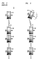
- FIG. 2 is a schematic top view of portion 21 of the apparatus of FIG. 1.
- a torque is applied to the fiber such that a spin is impressed on the fiber.
- the torque could be applied at any downstream point (prior to take-up) at which the fiber has cooled sufficiently to be contacted, it is generally not desirable to contact the bare fiber.
- the torque advantageously is applied at a point downstream from curing station 17, typically at an appropriate point in region 21. It is currently most preferred to apply the torque by means of the first guide roller.
- an intermittent torque can be applied to the fiber, such that a twist with non-constant pitch is impressed on the fiber.
- This can, for instance, be accomplished by changing the orientation of guide roller 1911 of FIG. 3, exemplarily by canting the roller by an angle ⁇ around a direction parallel to the draw tower axis.
- Canting roller 1911 causes the fiber to oscillate back and forth on the roller, in response to lateral forces that automatically arise in this arrangement. More specifically, the lateral forces translate into a torque on the fiber, which causes the fiber to roll laterally on roller 1911, thereby moving the fiber out of the plane defined by the fiber in the prior art (un-canted) apparatus. It will be appreciated that the lateral roll is superimposed on the conventional draw motion.
- the lateral motion of the fiber is believed to give rise to a restoring force that increases with increasing lateral displacement of the fiber, causing the fiber to jump back (substantially, but not necessarily exactly) into the plane, only to immediately begin another sidewise roll.
- This non-symmetrical back-and-forth motion is indicated by the double-headed arrow adjacent to roller 1911 in FIG. 3.
- the angular rotation speed of the fiber during the lateral roll is, inter alia, a function of the cant angle ⁇ .
- the pitch of the spin impressed on the fiber is also a function of ⁇ .
- the described exemplary method not only impresses a spin on the fiber but also introduces a substantially equal and opposite (generally elastic) twist into the taken-up fiber.
- a substantially equal and opposite (generally elastic) twist into the taken-up fiber.
- the elastic twist can, for instance, be removed by appropriate respooling.
- Guide roller 1912 of FIG. 4 can be caused to oscillate back and forth by any appropriate means, e.g., by eccentric drive means (not shown).
- An alternate arrangement is schematically shown in FIG. 5, wherein guide roller 1913 is caused to move back and forth axially, by appropriate conventional means that are not shown, resulting in alternate application of clockwise and counterclockwise torque on the fiber.
- the guide and drive means 21 of FIG. 1 can take many forms. For instance, sheaves (as shown in FIGs. 1-3) may be used, or ungrooved rollers may be used, or sheaves and ungrooved rollers may be used in combination (exemplarily as shown in FIGs. 4 and 5). All appropriate guide and drive means are contemplated, as are all appropriate means for applying an appropriate torque to the fiber.
- FIG. 6 shows exemplary experimental data, namely, the spin spatial frequency (in spins/m) as a function of distance along the fiber.
- Curve 60 was obtained from a single mode fiber which was drawn at 1.5 m/second, with 60 cycles/minute of the oscillating guide roller 1912 of FIG. 4), and curve 61 from an otherwise identical single mode fiber which was drawn at 3 m/second, with 106 cycles/minute of roller 1912. As can be seen from FIG.
- each of the fibers contains portions whose spin spatial frequency is far in excess of 4 spins/m (even in excess of 20 spins/m), and in each of the fibers the spin is non-constant, even having clockwise and counterclockwise helicity, resulting in substantial likelihood that the spin comprises a component that is effective in coupling the two polarization modes.
- the pitch of the spin impressed on fiber drawn in apparatus of the type shown in FIG. 4 depends, inter alia, on the oscillation amplitude 2 ⁇ ' and the oscillation frequency.
- ⁇ ' was about 15°
- the oscillation frequency was about 106 cycles/minute.
Landscapes
- Chemical & Material Sciences (AREA)
- Engineering & Computer Science (AREA)
- Physics & Mathematics (AREA)
- Manufacturing & Machinery (AREA)
- Life Sciences & Earth Sciences (AREA)
- General Life Sciences & Earth Sciences (AREA)
- Geochemistry & Mineralogy (AREA)
- Materials Engineering (AREA)
- Organic Chemistry (AREA)
- Dispersion Chemistry (AREA)
- Optics & Photonics (AREA)
- General Physics & Mathematics (AREA)
- Optical Fibers, Optical Fiber Cores, And Optical Fiber Bundles (AREA)
- Manufacture, Treatment Of Glass Fibers (AREA)
- Optical Communication System (AREA)
Abstract
Description
- This invention pertains to optical fibers, in particular, to single mode optical fiber having relatively low polarization mode dispersion (PMD). It also pertains to communication systems that comprise such fiber, and to methods of making such fiber.
- An ideal circularly symmetric "single mode" optical fiber can support two independent, degenerate modes of orthogonal polarization. Either one of these constitutes the fundamental HE₁₁ mode. In general, the electric field of light propagating along the fiber is a linear superposition of these two polarization eigenmodes.
- In practical single mode fiber, various imperfections such as asymmetrical lateral stress and a non-circular core typically break the circular symmetry of the ideal fiber and lift the degeneracy of these two polarization modes. The two modes then propagate with different phase velocities, and this difference between their effective refractive indices is called birefringence.
- Fiber birefringence can result from either a geometrical deformation or from various elasto-optic, magneto-optic or electro-optic index changes. In so-called polarization-preserving fibers asymmetry is deliberately introduced into the fiber. However, in ordinary (non-polarization-preserving) fibers the birefringence mechanisms act on the fiber in substantially unpredictable manner. Thus, the polarization state of the guided light will typically evolve through a pseudorandom sequence of states along the fiber, with the polarization state at the fiber output typically being both unpredictable and unstable. On average, a given polarization state in a given fiber is reproduced after a certain length Lp, the polarization "beat" length associated with the given fiber.
- The presence of birefringence in conventional single mode fiber results in signal dispersion (so-called polarization mode dispersion or PMD) and thus typically is undesirable, especially for applications that involve high bit rates or analog transmission (e.g., for optical fiber analog CATV systems).
- It is known that fiber having low PMD can be produced by rapidly spinning the preform while pulling the fiber from the preform. The prior art teaches that this results in periodically interchanged fast and slow birefringence axes along the fiber, which can lead to very low net birefringence due to piecemeal compensation of the relative phase delay between the polarization eigenmodes, provided the spin pitch is much less than the "un-spun" fiber beat length. See, for instance, A. Ashkin et al., Applied Optics, Vol. 20(13), p. 2299; A. J. Barlow et al., Applied Optics, Vol. 20(17), p. 2962; and S. C. Rashleigh, Laser Focus, May 1983.
- It is primarily the prior art requirement that the spin pitch be much less than the "unspun" Lp which makes the prior art technique substantially unsuitable for current commercial fiber production. For instance, assuming that the unspun Lp is about 1 m and the draw speed is 10 m/seconds, then the preform has to be spun at 6000 rpm in order to yield a spin pitch that is 1/10th of the unspun Lp. This is typically not practical in commercial fiber production.
- In view of the commercial significance of low birefringence optical fiber, it would be highly desirable to have available a technique for producing such fiber that is compatible with current commercial practice, e.g., that is usable even at the high draw speeds that are typically used now. This application discloses such a technique.
-
- FIG. 1 schematically depicts exemplary prior art fiber draw apparatus;
- FIG. 2 shows, schematically and in top view, the guide portion of the apparatus of FIG. 1;
- FIGs. 3-5 depict, also schematically and in top view, exemplary guide portions that can be used to practice the invention; and
- FIG. 6 shows exemplary data on spin vs. distance along the fiber, for fiber according to the invention.
- The invention is as defined by the claims. Broadly speaking, the invention is embodied in a novel and convenient method of making optical fiber, typically single mode fiber, that can be used to produce fiber having low PMD, exemplarily less than 0.5 ps/km1/2. It is also embodied in a novel type of low PMD fiber, and in articles (e.g., an optical fiber communication system) that comprise such fiber.
- More specifically, the inventive method comprises providing a conventional optical fiber preform, heating at least a portion of the preform to a conventional draw temperature, and drawing optical fiber from the heated preform in such a way that a spin is impressed on the fiber. Significantly, a torque is applied to the fiber such that the fiber is caused to twist around its longitudinal axis, with a resulting torsional deformation of the fiber material in the hot zone.
- A spin is "impressed" on the fiber herein if fiber material in the hot zone is caused to be torsionally deformed, with that deformation being frozen into the fiber, such that the fiber exhibits a permanent "spin", i.e., a permanent torsional deformation. The existence of such a frozen-in spin can be readily ascertained, e.g., by microscopic examination of the fiber to determine rotation of core ovality or eccentricity, or by means of a traveling magneto-optic modulator, as used by M. J. Marrone et al., Optics Letters, Vol. 12(1), p. 60. Associated with such a frozen-in spin is a pitch, the spin repeat distance along the fiber.
- As will be readily appreciated by those skilled in the art, the prior art method of spinning the preform results in a spin of essentially constant pitch. It is known that small twists of the symmetry axes can occur during the drawing process such that even conventional single-mode fibers exhibit a variation in the optical polarization along the fiber. See, for instance, the above cited Marrone et al. paper. However, we know of no case of prior art fiber with unintended spin whose spin had a spatial frequency in excess of 4 spins/meter. See, for instance, M. J. Marrone et al., op. cit., Table 1. Fiber having such low spin typically does not exhibit commercially significant reduction in PMD. Thus, fiber according to the invention comprises a portion or portions having spin spatial frequency in excess of 4 spins/meter, preferably in excess of 10 or even 20 spins/meter.
- In currently preferred embodiments of the invention, the torque is applied intermittently to the fiber, whereby the spin impressed on the fiber has a pitch that is not constant over substantial lengths of fiber, e.g., is not constant over the beat length Lp. We currently believe that non-constant pitch can have advantages over constant pitch, since low pitch can also couple the two polarization modes, provided the pitch is precisely matched with the fiber birefringence spatial frequency. See, for instance, S. C. Rashleigh, J. of Lightwave Technology, Vol. LT-1(2), pp. 312-331, especially p. 320, where it is stated that, "...regardless of the actual distribution f(z) of the birefringence perturbations, only the one spectral component with frequency βi can couple the two polarization eigenmodes. All other spectral components do not efficiently couple the modes". The parameter βi is the intrinsic birefringence of the fiber, and F(βi) is the Fourier transform of f(z). Since the perturbation f(z) is essentially random, it is clear that a constant pitch spin will typically not result in efficient mode coupling. On the other hand, non-constant pitch spin, especially spin that has alternately positive and negative helicity, is likely to contain spatial components that produce efficient coupling. We currently believe that strong coupling can be obtained with spin of varying spatial frequency that comprises, in addition to regions of relatively high spin spatial frequency, regions of relatively low spin spatial frequency. This is, for instance, the case if the spin alternates between positive and negative helicity.
- The invention is also embodied in optical fiber (exemplarily SiO₂-based fiber comprising a core and a cladding, with the former having larger effective refractive index than the cladding material that surrounds the core) that is produced by the inventive method. It is also embodied in an article (e.g., an optical fiber communication system that comprises a source of an optical signal, means for detecting an optical signal, and an optical fiber according to the invention signal-transmissively connecting the detector means and the source. More specifically, a spin is impressed on the fiber, with the spin not being constant along the fiber, and with at least a portion of the fiber having a spatial spin frequency in excess of 4 spins/meter.
- FIG. 1 schematically depicts conventional (prior art)
drawing apparatus 10.Fiber preform 11 is slowly fed (by means of a feed mechanism that is not shown) intofurnace 12, wherefiber 13 is drawn from the necked down portion of the preform. The bare fiber passes through diameter monitor 14 intocoating applicator 15, wherein the polymer coating (frequently comprising an inner and an outer coating) is applied to the, by now relatively cool, bare fiber. After passing through coating concentricity monitor 16 the fiber passes through curingstation 17.Exemplarily 17 comprises UV lamps. Downstream from 17 is coating diameter monitor 18, followed by guide means (e.g.,rollers region 21. It will be noted thatguide roller 191 is the first contact point of the fiber with a solid. At this point the fiber is already protected by a cured polymer coating. It will also be noted that the draw force is provided bycapstan 20, and that the rotational speed of 20 determines the draw speed, which exemplarily can be as high as 20 m/second. From 20 the fiber typically is lead to (independently driven) take-up means, e.g., a take-up spool. Those skilled in the art will recognize that FIG. 1 shows several optional features (e.g., 14, 16, 18), and does not show all possible features (e.g., a hermetic coating chamber between 12 and 15). However, FIG. 10 exemplifies currently used conventional drawing apparatus. - In the prior art apparatus of FIG. 1 the fiber essentially moves in a single plane at least between its point of origin in the furnace and the capstan, and no twist is intentionally impressed on the fiber. See FIG. 2, which is a schematic top view of
portion 21 of the apparatus of FIG. 1. - According to the invention, a torque is applied to the fiber such that a spin is impressed on the fiber. Although in principle the torque could be applied at any downstream point (prior to take-up) at which the fiber has cooled sufficiently to be contacted, it is generally not desirable to contact the bare fiber. Thus, the torque advantageously is applied at a point downstream from curing
station 17, typically at an appropriate point inregion 21. It is currently most preferred to apply the torque by means of the first guide roller. - We have discovered that an intermittent torque can be applied to the fiber, such that a twist with non-constant pitch is impressed on the fiber. This can, for instance, be accomplished by changing the orientation of
guide roller 1911 of FIG. 3, exemplarily by canting the roller by an angle ϑ around a direction parallel to the draw tower axis. Cantingroller 1911 as indicated causes the fiber to oscillate back and forth on the roller, in response to lateral forces that automatically arise in this arrangement. More specifically, the lateral forces translate into a torque on the fiber, which causes the fiber to roll laterally onroller 1911, thereby moving the fiber out of the plane defined by the fiber in the prior art (un-canted) apparatus. It will be appreciated that the lateral roll is superimposed on the conventional draw motion. The lateral motion of the fiber is believed to give rise to a restoring force that increases with increasing lateral displacement of the fiber, causing the fiber to jump back (substantially, but not necessarily exactly) into the plane, only to immediately begin another sidewise roll. This non-symmetrical back-and-forth motion is indicated by the double-headed arrow adjacent toroller 1911 in FIG. 3. The angular rotation speed of the fiber during the lateral roll is, inter alia, a function of the cant angle ϑ. Thus, the pitch of the spin impressed on the fiber is also a function of ϑ. For instance, particular draw apparatus used by us yielded average pitches of 14 and 7 cm for ϑ = 7 and 15°, respectively. It will be appreciated that these values are exemplary only, since the pitch will depend, inter alia, on the configuration and height of the draw tower, the draw speed, the draw tension and the coating viscosity. - Those skilled in the art will recognize that the described exemplary method not only impresses a spin on the fiber but also introduces a substantially equal and opposite (generally elastic) twist into the taken-up fiber. Although such fiber may be acceptable for some purposes (e.g., for sensor purposes that require only a relatively short length of fiber), it will generally be desirable to remove (or prevent the introduction of) the unwanted elastic twist. The elastic twist can, for instance, be removed by appropriate respooling. However, it is preferable to substantially prevent introduction of the elastic twist. This can be accomplished by alternately imposing a clockwise and a counterclockwise torque on the fiber, exemplarily as described below.
- Causing the
guide roller 1912 of FIG. 4 to oscillate about an axis that is parallel to the fiber draw direction (which is typically the same as the draw tower axis) alternately impresses positive and negative spin on the fiber. Furthermore, the resulting positive and negative elastic twists on the fiber substantially cancel, such that the fiber on the take-up spool is substantially free of torsional elastic strain.Guide roller 1912 of FIG. 4 can be caused to oscillate back and forth by any appropriate means, e.g., by eccentric drive means (not shown). An alternate arrangement is schematically shown in FIG. 5, whereinguide roller 1913 is caused to move back and forth axially, by appropriate conventional means that are not shown, resulting in alternate application of clockwise and counterclockwise torque on the fiber. - Those skilled in the art will recognize that the guide and drive means 21 of FIG. 1 can take many forms. For instance, sheaves (as shown in FIGs. 1-3) may be used, or ungrooved rollers may be used, or sheaves and ungrooved rollers may be used in combination (exemplarily as shown in FIGs. 4 and 5). All appropriate guide and drive means are contemplated, as are all appropriate means for applying an appropriate torque to the fiber.
- FIG. 6 shows exemplary experimental data, namely, the spin spatial frequency (in spins/m) as a function of distance along the fiber.
Curve 60 was obtained from a single mode fiber which was drawn at 1.5 m/second, with 60 cycles/minute of theoscillating guide roller 1912 of FIG. 4), and curve 61 from an otherwise identical single mode fiber which was drawn at 3 m/second, with 106 cycles/minute ofroller 1912. As can be seen from FIG. 6, each of the fibers contains portions whose spin spatial frequency is far in excess of 4 spins/m (even in excess of 20 spins/m), and in each of the fibers the spin is non-constant, even having clockwise and counterclockwise helicity, resulting in substantial likelihood that the spin comprises a component that is effective in coupling the two polarization modes. - Those skilled in the art will appreciate that the pitch of the spin impressed on fiber drawn in apparatus of the type shown in FIG. 4 depends, inter alia, on the oscillation amplitude 2ϑ' and the oscillation frequency. For instance, in a particular fiber draw apparatus according to the invention ϑ' was about 15°, and the oscillation frequency was about 106 cycles/minute. These values are exemplary only, and those skilled in the art will, aided by the teachings herein, be able to not only adapt their draw apparatus to practice the invention but also to select draw parameters that are suitable for their particular apparatus.
Claims (10)
- A method of making an optical fiber comprisinga) providing an optical fiber preform (11);b) heating at least a portion of said preform; andc) drawing optical (13) fiber from the heated preform such that a spin is impressed on the fiber, associated with drawing the fiber being a draw direction;
CHARACTERIZED IN THATd) step c) comprises applying a torque to the fiber, said torque causing the fiber to undergo rotation around the longitudinal axis of the fiber such that the spin is impressed on the fiber as it is drawn from the preform, with the torque selected such that at least a portion of the fiber has a spin whose spatial frequency is greater than 4 spins/meter. - Method according to claim 1, wherein the torque is applied such that the spin impressed on the fiber does not have a constant spatial frequency.
- Method according to claim 1, wherein the torque is alternately applied in clockwise and counterclockwise direction, such that the spin impressed on the fiber is alternately clockwise and counterclockwise.
- Method according to claim 3, wherein step c) comprises coating the fiber with a polymer coating and causing the coated fiber to contact a guide roller, wherein the alternating torque is applied by means of said guide roller.
- Method according to claim 4, wherein applying the torque by means of the guide roller comprises causing the guide roller to oscillate about an axis that is substantially parallel to said draw direction.
- An article that comprises single mode optical fiber comprising a core and a cladding surrounding the core, with a spin impressed on the fiber,
CHARACTERIZED IN THAT
in at least a portion of the fiber the spin has a spatial frequency that exceeds 4 spins/meter, with the spin not being constant along the fiber. - Article according to claim 6, wherein associated with the fiber is a polarization mode dispersion (PMD), with the PMD of the fiber being less than 0.5 ps/km1/2.
- Article according to claim 6, wherein the spin is alternately clockwise and counterclockwise.
- Article according to claim 6, wherein the article is an optical fiber communication system that comprises an optical signal source, means for detecting an optical signal, with said single mode optical fiber signal-transmissively connecting said source and said detecting means.
- Optical fiber comprising a core and a cladding surrounding the core, with a spin impressed on the fiber, said fiber being single mode optical fiber produced according to the method of claim 1.
Applications Claiming Priority (2)
| Application Number | Priority Date | Filing Date | Title |
|---|---|---|---|
| US924278 | 1992-08-03 | ||
| US07/924,278 US5298047A (en) | 1992-08-03 | 1992-08-03 | Method of making a fiber having low polarization mode dispersion due to a permanent spin |
Publications (2)
| Publication Number | Publication Date |
|---|---|
| EP0582405A1 true EP0582405A1 (en) | 1994-02-09 |
| EP0582405B1 EP0582405B1 (en) | 2000-02-09 |
Family
ID=25450006
Family Applications (1)
| Application Number | Title | Priority Date | Filing Date |
|---|---|---|---|
| EP93305780A Expired - Lifetime EP0582405B1 (en) | 1992-08-03 | 1993-07-22 | Method of drawing an optical fibre and fibre produced thereby |
Country Status (10)
| Country | Link |
|---|---|
| US (2) | US5298047A (en) |
| EP (1) | EP0582405B1 (en) |
| JP (1) | JP2981088B2 (en) |
| KR (1) | KR100328205B1 (en) |
| CN (1) | CN1040201C (en) |
| CA (1) | CA2098747C (en) |
| DE (1) | DE69327823T2 (en) |
| DK (1) | DK0582405T3 (en) |
| MX (1) | MX9304583A (en) |
| TW (1) | TW279841B (en) |
Cited By (34)
| Publication number | Priority date | Publication date | Assignee | Title |
|---|---|---|---|---|
| EP0698582A3 (en) * | 1994-08-26 | 1996-11-13 | Sumitomo Electric Industries | Method of manufacturing a fiber to compensate for dispersion |
| WO1997007067A1 (en) * | 1995-08-16 | 1997-02-27 | Plasma Optical Fibre B.V. | Optical fiber with low polarisation mode dispersion |
| EP0744636A3 (en) * | 1995-05-24 | 1997-06-04 | At & T Corp | Method for manufacturing optical fibers with low polarization dispersion |
| WO1997026221A1 (en) * | 1996-01-22 | 1997-07-24 | Corning Incorporated | Optical fiberof modulated spin for reduced polarisation mode dispersion as well as process and apparatus for its manufacture |
| EP0795521A1 (en) * | 1996-03-14 | 1997-09-17 | Sumitomo Electric Industries, Ltd | Method and apparatus for drawing an optical fiber of reduced polarisation mode dispersion from a preform |
| AU690414B2 (en) * | 1995-03-01 | 1998-04-23 | Sumitomo Electric Industries, Ltd. | Optical fiber and method of manufacturing the same |
| WO1999046620A1 (en) * | 1998-03-12 | 1999-09-16 | Siemens Aktiengesellschaft | Optical transmission element and method for reducing its polarisation mode dispersion |
| WO1999050842A1 (en) * | 1998-03-30 | 1999-10-07 | Seagate Technology, Llc. | Low-birefringence optical fiber for use in an optical data storage system |
| WO1999067180A1 (en) * | 1998-06-24 | 1999-12-29 | Pirelli Cavi E Sistemi S.P.A. | Method and apparatus for twisting a coated optical fiber during drawing from a preform |
| WO2000014579A1 (en) * | 1998-09-09 | 2000-03-16 | Deutsche Telekom Ag | Optical junction section |
| WO2000017122A1 (en) * | 1998-09-24 | 2000-03-30 | Sumitomo Electric Industries, Ltd. | Method for producing optical fiber |
| US6076376A (en) * | 1995-03-01 | 2000-06-20 | Sumitomo Electric Industries, Ltd. | Method of making an optical fiber having an imparted twist |
| WO2000044680A1 (en) * | 1999-01-27 | 2000-08-03 | Sumitomo Electric Industries, Ltd. | Method and device for producing covered optical fiber and covered optical fiber |
| RU2162241C2 (en) * | 1995-08-10 | 2001-01-20 | Корнинг Инкорпорейтед | Single-mode fiber-optic waveguide (modifications) and method for manufacture of single-mode fiber-optic waveguide |
| US6229937B1 (en) | 1998-09-17 | 2001-05-08 | Corning Incorporated | Circularly polarized fiber in optical circuits |
| WO2001035132A1 (en) * | 1999-11-08 | 2001-05-17 | Sumitomo Electric Industries, Ltd. | Optical fiber, method for manufacturing same, and optical transmission system comprising the same |
| WO2000016139A3 (en) * | 1998-09-17 | 2001-11-22 | Corning Inc | Circularly polarized fiber in optical circuits |
| WO2002003115A1 (en) * | 2000-07-06 | 2002-01-10 | Pirelli Cavi E Sistemi S.P.A. | Optical fibre with reduced polarization mode dispersion and method for obtaining an optical fibre with reduced polarization mode dispersion |
| RU2178901C2 (en) * | 1995-04-13 | 2002-01-27 | Корнинг Инкорпорейтед | Single-mode fiber-optical waveguide with controlled dispersion and process of its manufacture ( variants ) |
| WO2002063354A1 (en) * | 2001-01-30 | 2002-08-15 | Sumitomo Electric Industries, Ltd. | Method and apparatus for manufacturing optical fiber |
| US6550282B2 (en) | 1998-06-24 | 2003-04-22 | Pirelli Cavi E Sistemi S.P.A. | Method and apparatus for manufacturing an optical fiber from a preform |
| US6574015B1 (en) | 1998-05-19 | 2003-06-03 | Seagate Technology Llc | Optical depolarizer |
| US6587421B1 (en) | 1998-03-30 | 2003-07-01 | Seagate Technology Llc | Refractive index matching means coupled to an optical fiber for eliminating spurious light |
| EP1413558A1 (en) * | 2002-10-23 | 2004-04-28 | Samsung Electronics Co., Ltd. | Method and apparatus for drawing optical fiber using spin-amplitude modulation |
| WO2004058654A1 (en) * | 2002-12-30 | 2004-07-15 | Pirelli & C. S.P.A. | Method for producing an optical fiber having low polarization mode dispersion |
| RU2233811C2 (en) * | 2001-06-13 | 2004-08-10 | Открытое акционерное общество Пермская научно-производственная приборостроительная компания | Method of manufacture of the twin-core single-mode light-guiding fiber keeping polarization of emission |
| EP1325894A3 (en) * | 2001-12-20 | 2004-09-15 | FITEL USA CORPORATION, (A Delaware Corporation) | Multimode optical fibers with increased bandwith |
| EP1475358A1 (en) * | 2003-05-05 | 2004-11-10 | FITEL USA CORPORATION (a Delaware Corporation) | Methods for modifying ovality of optical fiber preforms |
| EP1491511A1 (en) * | 2003-06-24 | 2004-12-29 | Alcatel | Anti-PMD system for optical fibres |
| WO2005021453A1 (en) * | 2003-08-29 | 2005-03-10 | Prysmian Cavi E Sistemi Energia S.R.L. | Process for producing a low polarization mode dispersion optical fiber |
| US6876804B2 (en) | 2003-03-20 | 2005-04-05 | Corning Incorporated | Method of making a spun optical fiber with low polarization mode dispersion |
| EP1239312A4 (en) * | 1999-09-27 | 2005-09-21 | Sumitomo Electric Industries | OPTICAL FIBER WITH DISTRIBUTION MANAGEMENT, METHOD FOR MANUFACTURING THE SAME, OPTICAL COMMUNICATION SYSTEM USE AND OPTICAL FIBER BASE MATERIAL |
| EP1571132A3 (en) * | 2004-03-02 | 2006-04-26 | Samsung Electronics Co., Ltd. | Method and apparatus for drawing an optical fibre |
| US10388028B2 (en) | 2014-06-17 | 2019-08-20 | Heraeus Quartz North America Llc | Apparatus and method for measurement of transparent cylindrical articles |
Families Citing this family (93)
| Publication number | Priority date | Publication date | Assignee | Title |
|---|---|---|---|---|
| GB2286937B (en) * | 1994-02-26 | 1998-06-10 | Northern Telecom Ltd | Spectral polarisation separator |
| JP4232910B2 (en) * | 1995-02-01 | 2009-03-04 | プラズマ オプティカル ファイバー ベスローテン フェンノートシャップ | Optical fiber manufacturing method with reduced polarization mode dispersion |
| US5867616A (en) * | 1995-08-10 | 1999-02-02 | Corning Incorporated | Polarization mode coupled single mode waveguide |
| US5704960A (en) * | 1995-12-20 | 1998-01-06 | Corning, Inc. | Method of forming an optical fiber for reduced polarization effects in amplifiers |
| TW342460B (en) * | 1996-01-16 | 1998-10-11 | Sumitomo Electric Industries | A dispersion shift fiber |
| US6163630A (en) * | 1996-02-15 | 2000-12-19 | Corning Incorporated | Method and apparatus for producing twisted solitons |
| EP0883577B1 (en) * | 1996-02-26 | 2002-07-24 | Corning Incorporated | Method for providing controlled spin in optical fiber |
| US6324872B1 (en) | 1996-04-12 | 2001-12-04 | Corning Incorporated | Method and apparatus for introducing controlled spin in optical fibers |
| US6189343B1 (en) | 1996-11-13 | 2001-02-20 | Fibre Ottiche Sud F.O.S. S.P.A. | Apparatus and method for forming an optical fiber |
| DE69710991T2 (en) * | 1996-11-13 | 2002-10-31 | Fibre Ottiche Sud F.O.S. S.P.A., Battipaglia | Device and method for producing an optical fiber |
| EP1030823A4 (en) * | 1997-09-25 | 2000-12-27 | Corning Inc | Draw constant downfeed process |
| JP3070604B2 (en) | 1998-09-24 | 2000-07-31 | 住友電気工業株式会社 | Manufacturing method of optical fiber |
| JP3070603B2 (en) | 1998-09-24 | 2000-07-31 | 住友電気工業株式会社 | Manufacturing method of optical fiber |
| US6891622B2 (en) | 1999-02-11 | 2005-05-10 | Kvh Industries, Inc. | Current sensor |
| US6853780B1 (en) * | 1999-03-31 | 2005-02-08 | Pirelli Cavi E Sistemi S.P.A. | Optical cable for telecommunications |
| JP4076702B2 (en) | 1999-05-14 | 2008-04-16 | 株式会社フジクラ | Optical fiber twist measurement method |
| JP2001048569A (en) * | 1999-08-04 | 2001-02-20 | Sumitomo Electric Ind Ltd | Optical fiber drawing method |
| AU7788800A (en) * | 1999-10-29 | 2001-05-14 | Pirelli Cavi E Sistemi S.P.A. | Method of measuring the twist imparted to an optical fibre and procedure for processing an optical fibre using this method |
| US6422043B1 (en) | 1999-11-16 | 2002-07-23 | Fitel Usa Corp. | Method of making an improved multimode optical fiber and fiber made by method |
| US6556732B1 (en) | 2000-06-07 | 2003-04-29 | Corning Incorporated | All fiber polarization mode dispersion compensator |
| US7120323B2 (en) | 2000-08-02 | 2006-10-10 | Kvh Industries, Inc. | Reduction of linear birefringence in circular-cored single-mode fiber |
| WO2002014231A2 (en) * | 2000-08-10 | 2002-02-21 | Yazaki Corporation | Process for making glass bodies having refractive index gradients |
| WO2002051763A1 (en) * | 2000-12-22 | 2002-07-04 | Sumitomo Electric Industries, Ltd. | Coated optical fiber and production method therefor |
| US7016576B2 (en) * | 2000-12-28 | 2006-03-21 | Pirelli S.P.A. | Method for producing an optical fibre telecommunications cable with reduced polarization mode dispersion |
| CA2440938A1 (en) * | 2001-03-16 | 2002-09-26 | Sumitomo Electric Industries, Ltd. | Optical fiber and method of manufacturing the same |
| JP3723471B2 (en) * | 2001-06-12 | 2005-12-07 | 株式会社フジクラ | Optical fiber recoating method |
| KR100414691B1 (en) * | 2001-07-19 | 2004-01-13 | 엘지전선 주식회사 | Apparatus for manufacturing a twisted optical fiber with low polarization mode dispersion |
| JP3861663B2 (en) * | 2001-11-12 | 2006-12-20 | 住友電気工業株式会社 | Optical fiber preform manufacturing method |
| KR100417000B1 (en) * | 2001-12-03 | 2004-02-05 | 삼성전자주식회사 | Apparatus for low polarization mode dispersion |
| KR100416970B1 (en) * | 2002-01-17 | 2004-02-05 | 삼성전자주식회사 | Spin device for low polarization mode dispersion of optical fiber |
| JP3765283B2 (en) * | 2002-04-01 | 2006-04-12 | 住友電気工業株式会社 | Optical fiber manufacturing method and manufacturing apparatus |
| US6791678B2 (en) | 2002-07-23 | 2004-09-14 | Fitel Usa Corp. | System and method for obtaining spin and mechanical twist data during optical fiber draw |
| US6859596B2 (en) * | 2002-07-23 | 2005-02-22 | Fitel Usa Corp. | Systems and methods for forming ultra-low PMD optical fiber using amplitude and frequency keyed fiber spin functions |
| US6704100B2 (en) | 2002-08-08 | 2004-03-09 | Fitel Usa Corp. | Systems and methods for accurately measuring low values of polarization mode dispersion in an optical fiber using localized external perturbation induced low mode coupling |
| KR100401342B1 (en) * | 2002-08-31 | 2003-10-10 | Lg Cable Ltd | Apparatus for spinning optical fiber and apparatus and method for fabricating optical fiber using the same |
| KR100441156B1 (en) * | 2002-08-31 | 2004-07-19 | 엘지전선 주식회사 | Method for monitoring spin imparted on the optical fiber and method for making an optical fiber by using the same |
| WO2004050573A1 (en) * | 2002-09-25 | 2004-06-17 | Giacomo Stefano Roba | Process for producing an optical fiber having a low polarization mode dispersion |
| US7035525B2 (en) * | 2002-09-26 | 2006-04-25 | Fitel Usa Corp. | Methods and apparatuses for correcting mechanical twist in optical fiber |
| US20040062515A1 (en) * | 2002-09-26 | 2004-04-01 | Garner Harry Douglas | Apparatuses and methods for imparting mechanical twist in optical fibers |
| KR100520646B1 (en) * | 2002-10-02 | 2005-10-13 | 삼성전자주식회사 | Optical fiber drawing method using spin-amplitude asymmetric control |
| FR2849438B1 (en) * | 2002-12-31 | 2005-03-18 | Cit Alcatel | METHOD FOR CONTROLLING THE MODAL POLARIZATION DISPERSION OF AN OPTICAL FIBER DURING FIBRAGE |
| NL1022315C2 (en) * | 2003-01-07 | 2004-07-13 | Draka Fibre Technology Bv | Method for manufacturing an optical fiber provided with variations in the refractive index. |
| US7310974B2 (en) * | 2003-01-13 | 2007-12-25 | Sterlite Optical Technologies Limited | Method for producing twisted optical fiber with reduced polarization mode dispersion |
| US7861556B2 (en) * | 2003-02-28 | 2011-01-04 | Corning Incorporated | Method and apparatus for impulsively spinning optical fiber |
| CN1209308C (en) * | 2003-03-28 | 2005-07-06 | 长飞光纤光缆有限公司 | Manufacture of low polarization mode dispersion single mode optical fibers and products thereby |
| KR100547755B1 (en) * | 2003-05-24 | 2006-01-31 | 삼성전자주식회사 | Optical fiber manufacturing apparatus and method using spin |
| US6993229B2 (en) * | 2003-09-30 | 2006-01-31 | Corning Incorporated | Method of making spun optical fiber with low PMD |
| DK1698597T3 (en) * | 2003-12-26 | 2013-06-03 | Fujikura Ltd | OPTICAL FIBER CIRCUIT DEVICE AND METHOD FOR MANUFACTURING OPTICAL FIBER |
| EP1706766B1 (en) | 2003-12-30 | 2009-04-22 | Prysmian S.p.A. | Low polarisation mode dispersion (pmd) optical fiber link, and method of making the same |
| US20050172675A1 (en) * | 2004-02-11 | 2005-08-11 | The Furukawa Electric Co., Ltd. | Method of and apparatus for manufacturing single mode optical fiber |
| DK1725853T3 (en) | 2004-02-20 | 2014-12-15 | Prysmian Spa | A process for determining characteristic parameters of the textile spun optical fibers |
| US20050188728A1 (en) * | 2004-03-01 | 2005-09-01 | Zhi Zhiou | Apparatus and method for manufacturing optical fiber including rotating optical fiber preforms during draw |
| JP2005292180A (en) * | 2004-03-31 | 2005-10-20 | Fuji Photo Film Co Ltd | Plastic optical fiber and its manufacturing method |
| US7483610B2 (en) * | 2004-05-03 | 2009-01-27 | Nufern | Optical fiber having reduced defect density |
| US7317857B2 (en) * | 2004-05-03 | 2008-01-08 | Nufem | Optical fiber for delivering optical energy to or from a work object |
| GB0418069D0 (en) * | 2004-08-12 | 2004-09-15 | Univ Bristol | Method for reducing depolarization |
| CA2585241A1 (en) * | 2004-10-24 | 2006-05-04 | Chiral Photonics, Inc. | Chiral in-fiber polarizer apparatus and method |
| JP4712359B2 (en) * | 2004-11-29 | 2011-06-29 | 古河電気工業株式会社 | Optical fiber manufacturing method |
| US20080141723A1 (en) * | 2004-12-02 | 2008-06-19 | Franco Cocchini | Method, System and Device for Imparting a Predetermined Rotation to an Optical Fibre |
| US7317855B2 (en) * | 2004-12-16 | 2008-01-08 | Corning Incorporated | Method of imparting twist to optical fiber |
| RU2302381C1 (en) * | 2005-12-09 | 2007-07-10 | Государственное образовательное учреждение высшего профессионального образования Московский государственный университет путей сообщения (МИИТ) | Method of manufacture of the optic fiber |
| EP1963233B1 (en) * | 2005-12-23 | 2014-04-30 | Prysmian S.p.A. | Method and apparatus for the production of optical fibers with reduced polarization mode dispersion |
| JP2007272060A (en) * | 2006-03-31 | 2007-10-18 | Furukawa Electric Co Ltd:The | Optical fiber ribbon core and optical fiber cable |
| PL2033029T3 (en) * | 2006-06-22 | 2019-05-31 | Prysmian Spa | Optical fiber having sinusoidal spin function |
| KR100808354B1 (en) * | 2006-08-17 | 2008-02-27 | 엘에스전선 주식회사 | Single mode optical fiber with reduced polarization mode dispersion and manufacturing method thereof |
| JP4851368B2 (en) * | 2007-03-05 | 2012-01-11 | 古河電気工業株式会社 | Optical fiber manufacturing method |
| TW200909766A (en) | 2007-08-28 | 2009-03-01 | Maruzen Co Ltd | Magazine ejector structure for air gun |
| US8111957B2 (en) * | 2008-07-10 | 2012-02-07 | Corning Incorporated | +cylindrical polarization beams |
| JP5481830B2 (en) | 2008-10-20 | 2014-04-23 | 住友電気工業株式会社 | Optical fiber manufacturing apparatus and manufacturing method |
| EP2341377B1 (en) * | 2008-10-20 | 2017-10-04 | Sumitomo Electric Industries, Ltd. | Method for producing optical fiber |
| WO2010050079A1 (en) * | 2008-10-31 | 2010-05-06 | 株式会社フジクラ | Device for producing optical fiber and method for producing optical fiber |
| PL2376840T3 (en) | 2009-01-09 | 2019-04-30 | John Zink Co Llc | Method and apparatus for monitoring combustion properties in an interior of a boiler |
| US20100296155A1 (en) * | 2009-05-19 | 2010-11-25 | Waterford Institute Of Technology | Optical fiber raman amplifier |
| KR101716917B1 (en) | 2009-08-10 | 2017-03-15 | 졸로 테크놀러지스, 아이엔씨. | Mitigation of optical signal noise using a multimode transmit fiber |
| FR2967154A1 (en) | 2010-11-08 | 2012-05-11 | Delachaux Sa | COOLING DEVICE FOR IMPROVED OPTICAL FIBER |
| FR2967155B1 (en) | 2010-11-08 | 2017-12-15 | Delachaux Sa | IMPROVED OPTICAL FIBER GUIDING DEVICE |
| CN102092937B (en) * | 2010-12-15 | 2012-10-31 | 北京交通大学 | Method and system for rapidly optimizing drawing technology of photonic crystal fiber |
| JP5778939B2 (en) | 2011-02-14 | 2015-09-16 | 株式会社フジクラ | Manufacturing method of optical fiber |
| JP5948136B2 (en) * | 2011-05-27 | 2016-07-06 | 株式会社フジクラ | Optical fiber and manufacturing method thereof |
| JP5948094B2 (en) * | 2012-03-07 | 2016-07-06 | 株式会社フジクラ | Optical fiber and optical fiber manufacturing method |
| KR101994509B1 (en) | 2012-04-19 | 2019-06-28 | 존 징크 컴파니 엘엘씨 | In-Furnace Retro-Reflectors with Steerable Tunable Diode Laser Absorption Spectrometer |
| DK2843449T3 (en) | 2012-04-26 | 2019-04-29 | Sumitomo Electric Industries | MULTI-CORN OPTICAL FIBER TRANSFER SYSTEM |
| JP5903123B2 (en) * | 2014-04-07 | 2016-04-13 | 株式会社フジクラ | Manufacturing method and manufacturing apparatus for optical fiber |
| EP3183585A1 (en) * | 2014-08-19 | 2017-06-28 | ABB Schweiz AG | Optical sensor with spun birefringent sensing fiber |
| RU2614535C1 (en) * | 2015-12-23 | 2017-03-28 | Федеральное государственное бюджетное образовательное учреждение высшего образования "Поволжский государственный университет телекоммуникаций и информатики" (ФГБОУ ВО ПГУТИ) | Method of reducing differential mode-dependent delay of fibre-optic transmission line |
| CN107065173B (en) * | 2017-05-26 | 2020-07-28 | 西安科技大学 | An ultra-miniature polarization controller |
| JP2020024306A (en) * | 2018-08-07 | 2020-02-13 | 株式会社フジクラ | Optical fiber and method of manufacturing optical fiber |
| CN111704357B (en) * | 2020-07-20 | 2024-07-30 | 上海传输线研究所(中国电子科技集团公司第二十三研究所) | A large core diameter single polarization optical fiber drawing device and method |
| JP7625993B2 (en) * | 2021-07-14 | 2025-02-04 | 住友電気工業株式会社 | Optical fiber and method for manufacturing optical fiber |
| US20250145524A1 (en) * | 2022-07-25 | 2025-05-08 | Sumitomo Electric Industries, Ltd. | Optical fiber production device and optical fiber production method |
| JP2024024846A (en) * | 2022-08-10 | 2024-02-26 | 住友電気工業株式会社 | Optical fiber manufacturing method and optical fiber |
| FR3140710A1 (en) * | 2022-10-06 | 2024-04-12 | Commissariat à l'Energie Atomique et aux Energies Alternatives | WIRED BATTERY CELL, AND ITS PREPARATION METHOD BY STRETCHING A PREFORM |
| CN120736793B (en) * | 2025-08-19 | 2025-11-18 | 长飞光纤光缆股份有限公司 | A method and apparatus for manufacturing low polarization mode dispersion hollow-core optical fiber |
Citations (4)
| Publication number | Priority date | Publication date | Assignee | Title |
|---|---|---|---|---|
| DE2855337A1 (en) * | 1978-12-21 | 1980-07-03 | Licentia Gmbh | Double refraction compensation in faraday cylinder optical fibres - by inducing axial torsional distortion prior to winding |
| DE3010005B1 (en) * | 1980-03-15 | 1981-02-12 | Licentia Gmbh | Optical fiber twisted in its longitudinal axis |
| EP0078732A1 (en) * | 1981-11-03 | 1983-05-11 | Thomson-Csf | Method and apparatus for drawing in optical fibres twisted lengthwise, starting from softened glass |
| EP0112222A1 (en) * | 1982-12-10 | 1984-06-27 | Thomson-Csf | Device for producing a toroidal-shaped article starting from a pliable material |
Family Cites Families (13)
| Publication number | Priority date | Publication date | Assignee | Title |
|---|---|---|---|---|
| US4028081A (en) * | 1975-12-11 | 1977-06-07 | Bell Telephone Laboratories, Incorporated | Method for manufacturing helical optical fiber |
| US4308045A (en) * | 1978-03-10 | 1981-12-29 | Bell Telephone Laboratories, Incorporated | Method for fabricating optical fibers with enhanced mode coupling |
| US4205899A (en) * | 1978-06-08 | 1980-06-03 | Northern Telecom Limited | Optical cables |
| US4154049A (en) * | 1978-06-08 | 1979-05-15 | Northern Telecom Limited | Method and apparatus for forming optical cables |
| DE2908752A1 (en) * | 1979-03-06 | 1980-09-18 | Max Planck Gesellschaft | OPTICAL TRANSMISSION FILTER |
| US4248035A (en) * | 1979-04-02 | 1981-02-03 | Northern Telecom Limited | Apparatus and method used in the assembly of fibre optic cables |
| FR2515693B1 (en) * | 1981-11-03 | 1985-10-11 | Thomson Csf | METHOD FOR MANUFACTURING AN OBJECT HAVING A CHIRAL STRUCTURE ARISING FROM A SOURCE OF FORMABLE MATERIAL AND DEVICE USING THE SAME |
| US4556314A (en) * | 1983-08-31 | 1985-12-03 | At&T Bell Laboratories | Dispersion determining method and apparatus |
| FR2559275B1 (en) * | 1984-02-02 | 1988-04-08 | Thomson Csf | METHOD FOR MANUFACTURING AN OPTICAL FIBER WITH A CHIRAL STRUCTURE AND DEVICE CARRYING OUT THIS METHOD |
| US4606605A (en) * | 1984-06-29 | 1986-08-19 | At&T Bell Laboratories | Optical fiber having in-line polarization filter |
| JPS6414126A (en) * | 1987-07-06 | 1989-01-18 | Hitachi Cable | Optical fiber drawing device |
| JPS6450002A (en) * | 1987-08-21 | 1989-02-27 | Seiko Instr & Electronics | Optical attenuator and its manufacture |
| US5227623A (en) * | 1992-01-31 | 1993-07-13 | Hewlett-Packard Company | Method and apparatus for measuring polarization mode dispersion in optical devices |
-
1992
- 1992-08-03 US US07/924,278 patent/US5298047A/en not_active Expired - Lifetime
-
1993
- 1993-06-15 TW TW082104752A patent/TW279841B/zh not_active IP Right Cessation
- 1993-06-18 CA CA002098747A patent/CA2098747C/en not_active Expired - Lifetime
- 1993-07-22 DK DK93305780T patent/DK0582405T3/en active
- 1993-07-22 EP EP93305780A patent/EP0582405B1/en not_active Expired - Lifetime
- 1993-07-22 DE DE69327823T patent/DE69327823T2/en not_active Expired - Lifetime
- 1993-07-29 MX MX9304583A patent/MX9304583A/en not_active IP Right Cessation
- 1993-08-02 KR KR1019930014964A patent/KR100328205B1/en not_active Expired - Lifetime
- 1993-08-02 CN CN93109633A patent/CN1040201C/en not_active Expired - Fee Related
- 1993-08-03 JP JP5209977A patent/JP2981088B2/en not_active Expired - Lifetime
-
1994
- 1994-10-03 US US08/317,409 patent/US5418881A/en not_active Expired - Lifetime
Patent Citations (4)
| Publication number | Priority date | Publication date | Assignee | Title |
|---|---|---|---|---|
| DE2855337A1 (en) * | 1978-12-21 | 1980-07-03 | Licentia Gmbh | Double refraction compensation in faraday cylinder optical fibres - by inducing axial torsional distortion prior to winding |
| DE3010005B1 (en) * | 1980-03-15 | 1981-02-12 | Licentia Gmbh | Optical fiber twisted in its longitudinal axis |
| EP0078732A1 (en) * | 1981-11-03 | 1983-05-11 | Thomson-Csf | Method and apparatus for drawing in optical fibres twisted lengthwise, starting from softened glass |
| EP0112222A1 (en) * | 1982-12-10 | 1984-06-27 | Thomson-Csf | Device for producing a toroidal-shaped article starting from a pliable material |
Non-Patent Citations (3)
| Title |
|---|
| JOURNAL OF LIGHTWAVE TECHNOLOGY. vol. 6, no. 9, September 1988, NEW YORK US pages 1402 - 1405 C.G.ASKINS ET AL. 'technique for controlling the internal rotation of principal axes in the fabrication of birefringent fibers' * |
| NAVY TECHNICAL DISCLOSURE BULLETIN vol. 5, no. 12, December 1980, ARLINGTON, VA., US pages 7 - 12 S.C.RACHLEIGH 'FABRICATION OF CIRCULARLY BIREFRINGENT SINGLE MODE FIBERS' * |
| PATENT ABSTRACTS OF JAPAN vol. 13, no. 187 (C-592)2 May 1989 & JP-A-01 014 126 ( HITACHI CABLE LTD. ) 18 January 1989 * |
Cited By (51)
| Publication number | Priority date | Publication date | Assignee | Title |
|---|---|---|---|---|
| EP0698582A3 (en) * | 1994-08-26 | 1996-11-13 | Sumitomo Electric Industries | Method of manufacturing a fiber to compensate for dispersion |
| US6076376A (en) * | 1995-03-01 | 2000-06-20 | Sumitomo Electric Industries, Ltd. | Method of making an optical fiber having an imparted twist |
| US6347537B1 (en) | 1995-03-01 | 2002-02-19 | Sumitomo Electric Industries, Ltd. | Method of drawing a twisted optical fiber |
| AU690414B2 (en) * | 1995-03-01 | 1998-04-23 | Sumitomo Electric Industries, Ltd. | Optical fiber and method of manufacturing the same |
| EP0729919A3 (en) * | 1995-03-01 | 1998-12-23 | Sumitomo Electric Industries, Ltd. | Optical fiber and method of manufacturing the same |
| RU2178901C2 (en) * | 1995-04-13 | 2002-01-27 | Корнинг Инкорпорейтед | Single-mode fiber-optical waveguide with controlled dispersion and process of its manufacture ( variants ) |
| EP0744636A3 (en) * | 1995-05-24 | 1997-06-04 | At & T Corp | Method for manufacturing optical fibers with low polarization dispersion |
| RU2162241C2 (en) * | 1995-08-10 | 2001-01-20 | Корнинг Инкорпорейтед | Single-mode fiber-optic waveguide (modifications) and method for manufacture of single-mode fiber-optic waveguide |
| WO1997007067A1 (en) * | 1995-08-16 | 1997-02-27 | Plasma Optical Fibre B.V. | Optical fiber with low polarisation mode dispersion |
| US5897680A (en) * | 1995-08-16 | 1999-04-27 | Plasma Optical Fibre B.V. | Method of making a twisted optical fiber with low polarisation mode dispersion |
| CN1113823C (en) * | 1996-01-22 | 2003-07-09 | 康宁股份有限公司 | Optical fiber with modulation rotation for reduced polarization mode dispersion |
| WO1997026221A1 (en) * | 1996-01-22 | 1997-07-24 | Corning Incorporated | Optical fiberof modulated spin for reduced polarisation mode dispersion as well as process and apparatus for its manufacture |
| AU719604B2 (en) * | 1996-01-22 | 2000-05-11 | Corning Incorporated | Optical fiber of modulated spin for reduced polarisation mode dispersion as well as process and apparatus for its manufacture |
| EP0795521A1 (en) * | 1996-03-14 | 1997-09-17 | Sumitomo Electric Industries, Ltd | Method and apparatus for drawing an optical fiber of reduced polarisation mode dispersion from a preform |
| WO1999046620A1 (en) * | 1998-03-12 | 1999-09-16 | Siemens Aktiengesellschaft | Optical transmission element and method for reducing its polarisation mode dispersion |
| WO1999050842A1 (en) * | 1998-03-30 | 1999-10-07 | Seagate Technology, Llc. | Low-birefringence optical fiber for use in an optical data storage system |
| US6298027B1 (en) | 1998-03-30 | 2001-10-02 | Seagate Technology Llc | Low-birefringence optical fiber for use in an optical data storage system |
| US6587421B1 (en) | 1998-03-30 | 2003-07-01 | Seagate Technology Llc | Refractive index matching means coupled to an optical fiber for eliminating spurious light |
| US6574015B1 (en) | 1998-05-19 | 2003-06-03 | Seagate Technology Llc | Optical depolarizer |
| WO1999067180A1 (en) * | 1998-06-24 | 1999-12-29 | Pirelli Cavi E Sistemi S.P.A. | Method and apparatus for twisting a coated optical fiber during drawing from a preform |
| US6550282B2 (en) | 1998-06-24 | 2003-04-22 | Pirelli Cavi E Sistemi S.P.A. | Method and apparatus for manufacturing an optical fiber from a preform |
| US6813424B1 (en) | 1998-09-09 | 2004-11-02 | Deutsche Telekom Ag Bonn | Optical communications link |
| WO2000014579A1 (en) * | 1998-09-09 | 2000-03-16 | Deutsche Telekom Ag | Optical junction section |
| US6229937B1 (en) | 1998-09-17 | 2001-05-08 | Corning Incorporated | Circularly polarized fiber in optical circuits |
| WO2000016139A3 (en) * | 1998-09-17 | 2001-11-22 | Corning Inc | Circularly polarized fiber in optical circuits |
| WO2000017122A1 (en) * | 1998-09-24 | 2000-03-30 | Sumitomo Electric Industries, Ltd. | Method for producing optical fiber |
| US6519404B1 (en) | 1999-01-27 | 2003-02-11 | Sumitomo Electric Industries, Ltd. | Method and apparatus for fabricating coated optical fiber, and coated optical fiber |
| WO2000044680A1 (en) * | 1999-01-27 | 2000-08-03 | Sumitomo Electric Industries, Ltd. | Method and device for producing covered optical fiber and covered optical fiber |
| AU761479B2 (en) * | 1999-01-27 | 2003-06-05 | Sumitomo Electric Industries, Ltd. | Method and device for producing covered optical fiber and covered optical fiber |
| EP1239312A4 (en) * | 1999-09-27 | 2005-09-21 | Sumitomo Electric Industries | OPTICAL FIBER WITH DISTRIBUTION MANAGEMENT, METHOD FOR MANUFACTURING THE SAME, OPTICAL COMMUNICATION SYSTEM USE AND OPTICAL FIBER BASE MATERIAL |
| US6567597B2 (en) | 1999-11-08 | 2003-05-20 | Sumitomo Electric Industries, Ltd. | Optical fiber, method of making the same, and optical transmission system including the same |
| WO2001035132A1 (en) * | 1999-11-08 | 2001-05-17 | Sumitomo Electric Industries, Ltd. | Optical fiber, method for manufacturing same, and optical transmission system comprising the same |
| EP1258751A4 (en) * | 1999-11-08 | 2004-12-01 | Sumitomo Electric Industries | OPTICAL FIBER, MANUFACTURING METHOD THEREOF, AND OPTICAL TRANSMISSION SYSTEM CONTAINING THE SAME |
| WO2002003115A1 (en) * | 2000-07-06 | 2002-01-10 | Pirelli Cavi E Sistemi S.P.A. | Optical fibre with reduced polarization mode dispersion and method for obtaining an optical fibre with reduced polarization mode dispersion |
| US6920270B2 (en) | 2000-07-06 | 2005-07-19 | Pirelli Cavi E Sistemi S.P.A. | Optical fibre with reduced polarization mode dispersion and method for obtaining an optical fibre with reduced polarization mode dispersion |
| WO2002063354A1 (en) * | 2001-01-30 | 2002-08-15 | Sumitomo Electric Industries, Ltd. | Method and apparatus for manufacturing optical fiber |
| RU2233811C2 (en) * | 2001-06-13 | 2004-08-10 | Открытое акционерное общество Пермская научно-производственная приборостроительная компания | Method of manufacture of the twin-core single-mode light-guiding fiber keeping polarization of emission |
| EP1325894A3 (en) * | 2001-12-20 | 2004-09-15 | FITEL USA CORPORATION, (A Delaware Corporation) | Multimode optical fibers with increased bandwith |
| EP1413558A1 (en) * | 2002-10-23 | 2004-04-28 | Samsung Electronics Co., Ltd. | Method and apparatus for drawing optical fiber using spin-amplitude modulation |
| WO2004058654A1 (en) * | 2002-12-30 | 2004-07-15 | Pirelli & C. S.P.A. | Method for producing an optical fiber having low polarization mode dispersion |
| US7891216B2 (en) | 2002-12-30 | 2011-02-22 | Prysmian Cavi E Sistemi Energia S.R.L. | Method for producing an optical fiber having low polarization mode dispersion |
| US6876804B2 (en) | 2003-03-20 | 2005-04-05 | Corning Incorporated | Method of making a spun optical fiber with low polarization mode dispersion |
| EP1475358A1 (en) * | 2003-05-05 | 2004-11-10 | FITEL USA CORPORATION (a Delaware Corporation) | Methods for modifying ovality of optical fiber preforms |
| US7946133B2 (en) | 2003-05-05 | 2011-05-24 | Fitel Usa Corp. | Methods for modifying ovality of optical fiber preforms |
| EP1491511A1 (en) * | 2003-06-24 | 2004-12-29 | Alcatel | Anti-PMD system for optical fibres |
| US7209604B2 (en) | 2003-06-24 | 2007-04-24 | Alcatel | Anti-PMD system |
| FR2856805A1 (en) * | 2003-06-24 | 2004-12-31 | Cit Alcatel | SYSTEM WITH THE MODAL POLARIZATION DISPERSION OF AN OPTICAL FIBER |
| WO2005021453A1 (en) * | 2003-08-29 | 2005-03-10 | Prysmian Cavi E Sistemi Energia S.R.L. | Process for producing a low polarization mode dispersion optical fiber |
| US8322164B2 (en) | 2003-08-29 | 2012-12-04 | Prysmian Cavi E Sistemi Energia S.R.L. | Process for producing a low polarization mode dispersion optical fiber |
| EP1571132A3 (en) * | 2004-03-02 | 2006-04-26 | Samsung Electronics Co., Ltd. | Method and apparatus for drawing an optical fibre |
| US10388028B2 (en) | 2014-06-17 | 2019-08-20 | Heraeus Quartz North America Llc | Apparatus and method for measurement of transparent cylindrical articles |
Also Published As
| Publication number | Publication date |
|---|---|
| JP2981088B2 (en) | 1999-11-22 |
| DK0582405T3 (en) | 2000-06-13 |
| JPH06171970A (en) | 1994-06-21 |
| DE69327823T2 (en) | 2000-07-27 |
| MX9304583A (en) | 1994-02-28 |
| KR100328205B1 (en) | 2002-06-20 |
| DE69327823D1 (en) | 2000-03-16 |
| CA2098747A1 (en) | 1994-02-04 |
| CA2098747C (en) | 1998-09-15 |
| CN1083449A (en) | 1994-03-09 |
| CN1040201C (en) | 1998-10-14 |
| EP0582405B1 (en) | 2000-02-09 |
| KR940004351A (en) | 1994-03-15 |
| TW279841B (en) | 1996-07-01 |
| US5298047A (en) | 1994-03-29 |
| US5418881A (en) | 1995-05-23 |
Similar Documents
| Publication | Publication Date | Title |
|---|---|---|
| US5298047A (en) | Method of making a fiber having low polarization mode dispersion due to a permanent spin | |
| EP1325894B1 (en) | Multimode optical fibers with increased bandwith | |
| JP3599748B2 (en) | Optical fiber with low polarization mode dispersion | |
| US20010020374A1 (en) | Method and apparatus for manufacturing an optical fiber from a preform | |
| EP1384700A2 (en) | Apparatus and method for drawing an optical fibre of low polarisation mode dispersion | |
| US20050163434A1 (en) | Apparatus for applying spin to optical fiber and optical fiber manufacturing method and apparatus using the same | |
| US6876804B2 (en) | Method of making a spun optical fiber with low polarization mode dispersion | |
| CA2335836A1 (en) | Method and apparatus for twisting a coated optical fiber during drawing from a preform | |
| US6189343B1 (en) | Apparatus and method for forming an optical fiber | |
| KR100547755B1 (en) | Optical fiber manufacturing apparatus and method using spin | |
| WO2004078665A1 (en) | Method and apparatus for impulse spinning of an optical fiber during drawing | |
| JP4235733B2 (en) | Method for manufacturing low polarization mode dispersion optical fiber | |
| US6993229B2 (en) | Method of making spun optical fiber with low PMD | |
| CN120736793B (en) | A method and apparatus for manufacturing low polarization mode dispersion hollow-core optical fiber | |
| JP2001302272A (en) | Optical fiber manufacturing method and apparatus | |
| KR100642378B1 (en) | Device for improving polarization mode dispersion using pressure change around optical fiber and optical fiber manufacturing device using the same | |
| KR20050085928A (en) | Method for producing an optical fiber having low polarization mode dispersion |
Legal Events
| Date | Code | Title | Description |
|---|---|---|---|
| PUAI | Public reference made under article 153(3) epc to a published international application that has entered the european phase |
Free format text: ORIGINAL CODE: 0009012 |
|
| AK | Designated contracting states |
Kind code of ref document: A1 Designated state(s): DE DK FR GB IT |
|
| RAP3 | Party data changed (applicant data changed or rights of an application transferred) |
Owner name: AT&T CORP. |
|
| 17P | Request for examination filed |
Effective date: 19940728 |
|
| 17Q | First examination report despatched |
Effective date: 19960917 |
|
| GRAG | Despatch of communication of intention to grant |
Free format text: ORIGINAL CODE: EPIDOS AGRA |
|
| GRAG | Despatch of communication of intention to grant |
Free format text: ORIGINAL CODE: EPIDOS AGRA |
|
| GRAH | Despatch of communication of intention to grant a patent |
Free format text: ORIGINAL CODE: EPIDOS IGRA |
|
| GRAH | Despatch of communication of intention to grant a patent |
Free format text: ORIGINAL CODE: EPIDOS IGRA |
|
| GRAA | (expected) grant |
Free format text: ORIGINAL CODE: 0009210 |
|
| AK | Designated contracting states |
Kind code of ref document: B1 Designated state(s): DE DK FR GB IT |
|
| REF | Corresponds to: |
Ref document number: 69327823 Country of ref document: DE Date of ref document: 20000316 |
|
| ITF | It: translation for a ep patent filed | ||
| ET | Fr: translation filed | ||
| REG | Reference to a national code |
Ref country code: DK Ref legal event code: T3 |
|
| PLBE | No opposition filed within time limit |
Free format text: ORIGINAL CODE: 0009261 |
|
| STAA | Information on the status of an ep patent application or granted ep patent |
Free format text: STATUS: NO OPPOSITION FILED WITHIN TIME LIMIT |
|
| 26N | No opposition filed | ||
| REG | Reference to a national code |
Ref country code: GB Ref legal event code: IF02 |
|
| PGFP | Annual fee paid to national office [announced via postgrant information from national office to epo] |
Ref country code: DK Payment date: 20110725 Year of fee payment: 19 |
|
| PGFP | Annual fee paid to national office [announced via postgrant information from national office to epo] |
Ref country code: GB Payment date: 20120725 Year of fee payment: 20 |
|
| PGFP | Annual fee paid to national office [announced via postgrant information from national office to epo] |
Ref country code: DE Payment date: 20120727 Year of fee payment: 20 Ref country code: IT Payment date: 20120724 Year of fee payment: 20 Ref country code: FR Payment date: 20120731 Year of fee payment: 20 |
|
| REG | Reference to a national code |
Ref country code: DE Ref legal event code: R071 Ref document number: 69327823 Country of ref document: DE |
|
| REG | Reference to a national code |
Ref country code: DK Ref legal event code: EUP |
|
| REG | Reference to a national code |
Ref country code: GB Ref legal event code: PE20 Expiry date: 20130721 |
|
| PG25 | Lapsed in a contracting state [announced via postgrant information from national office to epo] |
Ref country code: DE Free format text: LAPSE BECAUSE OF EXPIRATION OF PROTECTION Effective date: 20130723 |
|
| PG25 | Lapsed in a contracting state [announced via postgrant information from national office to epo] |
Ref country code: GB Free format text: LAPSE BECAUSE OF EXPIRATION OF PROTECTION Effective date: 20130721 |