JP3861663B2 - Optical fiber preform manufacturing method - Google Patents
Optical fiber preform manufacturing method Download PDFInfo
- Publication number
- JP3861663B2 JP3861663B2 JP2001346511A JP2001346511A JP3861663B2 JP 3861663 B2 JP3861663 B2 JP 3861663B2 JP 2001346511 A JP2001346511 A JP 2001346511A JP 2001346511 A JP2001346511 A JP 2001346511A JP 3861663 B2 JP3861663 B2 JP 3861663B2
- Authority
- JP
- Japan
- Prior art keywords
- glass
- glass pipe
- optical fiber
- reduced diameter
- pipe
- Prior art date
- Legal status (The legal status is an assumption and is not a legal conclusion. Google has not performed a legal analysis and makes no representation as to the accuracy of the status listed.)
- Expired - Fee Related
Links
- 239000013307 optical fiber Substances 0.000 title claims description 267
- 238000004519 manufacturing process Methods 0.000 title claims description 83
- 239000011521 glass Substances 0.000 claims description 932
- VYPSYNLAJGMNEJ-UHFFFAOYSA-N Silicium dioxide Chemical compound O=[Si]=O VYPSYNLAJGMNEJ-UHFFFAOYSA-N 0.000 claims description 85
- 238000010438 heat treatment Methods 0.000 claims description 75
- 238000000034 method Methods 0.000 claims description 54
- 238000003780 insertion Methods 0.000 claims description 52
- 230000037431 insertion Effects 0.000 claims description 52
- 239000000460 chlorine Substances 0.000 claims description 48
- 230000010354 integration Effects 0.000 claims description 44
- 229910052801 chlorine Inorganic materials 0.000 claims description 11
- 229910052731 fluorine Inorganic materials 0.000 claims description 11
- ZAMOUSCENKQFHK-UHFFFAOYSA-N Chlorine atom Chemical compound [Cl] ZAMOUSCENKQFHK-UHFFFAOYSA-N 0.000 claims description 9
- 229910052698 phosphorus Inorganic materials 0.000 claims description 8
- PXGOKWXKJXAPGV-UHFFFAOYSA-N Fluorine Chemical compound FF PXGOKWXKJXAPGV-UHFFFAOYSA-N 0.000 claims description 7
- 239000011737 fluorine Substances 0.000 claims description 7
- OAICVXFJPJFONN-UHFFFAOYSA-N Phosphorus Chemical compound [P] OAICVXFJPJFONN-UHFFFAOYSA-N 0.000 claims description 6
- 239000011574 phosphorus Substances 0.000 claims description 6
- 238000002360 preparation method Methods 0.000 claims 1
- 239000007789 gas Substances 0.000 description 77
- 238000005253 cladding Methods 0.000 description 29
- 239000006185 dispersion Substances 0.000 description 24
- 230000000052 comparative effect Effects 0.000 description 16
- 230000010287 polarization Effects 0.000 description 16
- 238000002844 melting Methods 0.000 description 13
- 230000008018 melting Effects 0.000 description 13
- 230000005540 biological transmission Effects 0.000 description 12
- 238000005530 etching Methods 0.000 description 12
- 239000000463 material Substances 0.000 description 12
- 238000005259 measurement Methods 0.000 description 10
- 230000002093 peripheral effect Effects 0.000 description 10
- 229910005793 GeO 2 Inorganic materials 0.000 description 8
- 229910018503 SF6 Inorganic materials 0.000 description 8
- 239000004809 Teflon Substances 0.000 description 8
- 229920006362 Teflon® Polymers 0.000 description 8
- 230000001681 protective effect Effects 0.000 description 8
- SFZCNBIFKDRMGX-UHFFFAOYSA-N sulfur hexafluoride Chemical compound FS(F)(F)(F)(F)F SFZCNBIFKDRMGX-UHFFFAOYSA-N 0.000 description 8
- 229960000909 sulfur hexafluoride Drugs 0.000 description 8
- 239000011261 inert gas Substances 0.000 description 7
- 230000007423 decrease Effects 0.000 description 6
- 230000009467 reduction Effects 0.000 description 6
- 230000000694 effects Effects 0.000 description 5
- 239000002245 particle Substances 0.000 description 5
- KRHYYFGTRYWZRS-UHFFFAOYSA-N Fluorane Chemical compound F KRHYYFGTRYWZRS-UHFFFAOYSA-N 0.000 description 4
- 239000012535 impurity Substances 0.000 description 4
- 238000007689 inspection Methods 0.000 description 4
- 230000008569 process Effects 0.000 description 4
- 239000000919 ceramic Substances 0.000 description 3
- 230000006837 decompression Effects 0.000 description 3
- 238000010586 diagram Methods 0.000 description 3
- 230000003287 optical effect Effects 0.000 description 3
- 238000005452 bending Methods 0.000 description 2
- 230000015572 biosynthetic process Effects 0.000 description 2
- 230000008878 coupling Effects 0.000 description 2
- 238000010168 coupling process Methods 0.000 description 2
- 238000005859 coupling reaction Methods 0.000 description 2
- 238000009826 distribution Methods 0.000 description 2
- 230000002349 favourable effect Effects 0.000 description 2
- 239000000835 fiber Substances 0.000 description 2
- 230000004927 fusion Effects 0.000 description 2
- QPJSUIGXIBEQAC-UHFFFAOYSA-N n-(2,4-dichloro-5-propan-2-yloxyphenyl)acetamide Chemical compound CC(C)OC1=CC(NC(C)=O)=C(Cl)C=C1Cl QPJSUIGXIBEQAC-UHFFFAOYSA-N 0.000 description 2
- 239000010453 quartz Substances 0.000 description 2
- 239000002344 surface layer Substances 0.000 description 2
- 238000011179 visual inspection Methods 0.000 description 2
- IJGRMHOSHXDMSA-UHFFFAOYSA-N Atomic nitrogen Chemical compound N#N IJGRMHOSHXDMSA-UHFFFAOYSA-N 0.000 description 1
- 230000005856 abnormality Effects 0.000 description 1
- 239000000654 additive Substances 0.000 description 1
- QVGXLLKOCUKJST-UHFFFAOYSA-N atomic oxygen Chemical compound [O] QVGXLLKOCUKJST-UHFFFAOYSA-N 0.000 description 1
- 230000000994 depressogenic effect Effects 0.000 description 1
- 238000011038 discontinuous diafiltration by volume reduction Methods 0.000 description 1
- 239000000428 dust Substances 0.000 description 1
- 125000002887 hydroxy group Chemical group [H]O* 0.000 description 1
- 239000010410 layer Substances 0.000 description 1
- 238000012986 modification Methods 0.000 description 1
- 230000004048 modification Effects 0.000 description 1
- 238000012544 monitoring process Methods 0.000 description 1
- 230000010355 oscillation Effects 0.000 description 1
- 239000001301 oxygen Substances 0.000 description 1
- 229910052760 oxygen Inorganic materials 0.000 description 1
- 230000000149 penetrating effect Effects 0.000 description 1
- -1 polytetrafluoroethylene Polymers 0.000 description 1
- 229920001343 polytetrafluoroethylene Polymers 0.000 description 1
- 239000004810 polytetrafluoroethylene Substances 0.000 description 1
- 239000002243 precursor Substances 0.000 description 1
- 239000002994 raw material Substances 0.000 description 1
- 238000003786 synthesis reaction Methods 0.000 description 1
- 230000002194 synthesizing effect Effects 0.000 description 1
- 239000011800 void material Substances 0.000 description 1
Images

Classifications
-
- C—CHEMISTRY; METALLURGY
- C03—GLASS; MINERAL OR SLAG WOOL
- C03C—CHEMICAL COMPOSITION OF GLASSES, GLAZES OR VITREOUS ENAMELS; SURFACE TREATMENT OF GLASS; SURFACE TREATMENT OF FIBRES OR FILAMENTS MADE FROM GLASS, MINERALS OR SLAGS; JOINING GLASS TO GLASS OR OTHER MATERIALS
- C03C3/00—Glass compositions
- C03C3/04—Glass compositions containing silica
- C03C3/06—Glass compositions containing silica with more than 90% silica by weight, e.g. quartz
-
- C—CHEMISTRY; METALLURGY
- C03—GLASS; MINERAL OR SLAG WOOL
- C03B—MANUFACTURE, SHAPING, OR SUPPLEMENTARY PROCESSES
- C03B37/00—Manufacture or treatment of flakes, fibres, or filaments from softened glass, minerals, or slags
- C03B37/01—Manufacture of glass fibres or filaments
- C03B37/012—Manufacture of preforms for drawing fibres or filaments
- C03B37/01205—Manufacture of preforms for drawing fibres or filaments starting from tubes, rods, fibres or filaments
- C03B37/01211—Manufacture of preforms for drawing fibres or filaments starting from tubes, rods, fibres or filaments by inserting one or more rods or tubes into a tube
-
- C—CHEMISTRY; METALLURGY
- C03—GLASS; MINERAL OR SLAG WOOL
- C03B—MANUFACTURE, SHAPING, OR SUPPLEMENTARY PROCESSES
- C03B37/00—Manufacture or treatment of flakes, fibres, or filaments from softened glass, minerals, or slags
- C03B37/01—Manufacture of glass fibres or filaments
- C03B37/012—Manufacture of preforms for drawing fibres or filaments
- C03B37/01205—Manufacture of preforms for drawing fibres or filaments starting from tubes, rods, fibres or filaments
- C03B37/01225—Means for changing or stabilising the shape, e.g. diameter, of tubes or rods in general, e.g. collapsing
- C03B37/01228—Removal of preform material
-
- C—CHEMISTRY; METALLURGY
- C03—GLASS; MINERAL OR SLAG WOOL
- C03B—MANUFACTURE, SHAPING, OR SUPPLEMENTARY PROCESSES
- C03B37/00—Manufacture or treatment of flakes, fibres, or filaments from softened glass, minerals, or slags
- C03B37/01—Manufacture of glass fibres or filaments
- C03B37/012—Manufacture of preforms for drawing fibres or filaments
- C03B37/01205—Manufacture of preforms for drawing fibres or filaments starting from tubes, rods, fibres or filaments
- C03B37/01225—Means for changing or stabilising the shape, e.g. diameter, of tubes or rods in general, e.g. collapsing
- C03B37/01248—Means for changing or stabilising the shape, e.g. diameter, of tubes or rods in general, e.g. collapsing by collapsing without drawing
-
- C—CHEMISTRY; METALLURGY
- C03—GLASS; MINERAL OR SLAG WOOL
- C03B—MANUFACTURE, SHAPING, OR SUPPLEMENTARY PROCESSES
- C03B37/00—Manufacture or treatment of flakes, fibres, or filaments from softened glass, minerals, or slags
- C03B37/01—Manufacture of glass fibres or filaments
- C03B37/012—Manufacture of preforms for drawing fibres or filaments
- C03B37/01205—Manufacture of preforms for drawing fibres or filaments starting from tubes, rods, fibres or filaments
- C03B37/01225—Means for changing or stabilising the shape, e.g. diameter, of tubes or rods in general, e.g. collapsing
- C03B37/0126—Means for supporting, rotating, translating the rod, tube or preform
-
- G—PHYSICS
- G02—OPTICS
- G02B—OPTICAL ELEMENTS, SYSTEMS OR APPARATUS
- G02B6/00—Light guides; Structural details of arrangements comprising light guides and other optical elements, e.g. couplings
- G02B6/02—Optical fibres with cladding with or without a coating
- G02B6/02214—Optical fibres with cladding with or without a coating tailored to obtain the desired dispersion, e.g. dispersion shifted, dispersion flattened
- G02B6/02285—Characterised by the polarisation mode dispersion [PMD] properties, e.g. for minimising PMD
-
- C—CHEMISTRY; METALLURGY
- C03—GLASS; MINERAL OR SLAG WOOL
- C03B—MANUFACTURE, SHAPING, OR SUPPLEMENTARY PROCESSES
- C03B2201/00—Type of glass produced
- C03B2201/02—Pure silica glass, e.g. pure fused quartz
-
- C—CHEMISTRY; METALLURGY
- C03—GLASS; MINERAL OR SLAG WOOL
- C03B—MANUFACTURE, SHAPING, OR SUPPLEMENTARY PROCESSES
- C03B2201/00—Type of glass produced
- C03B2201/06—Doped silica-based glasses
- C03B2201/08—Doped silica-based glasses doped with boron or fluorine or other refractive index decreasing dopant
- C03B2201/10—Doped silica-based glasses doped with boron or fluorine or other refractive index decreasing dopant doped with boron
-
- C—CHEMISTRY; METALLURGY
- C03—GLASS; MINERAL OR SLAG WOOL
- C03B—MANUFACTURE, SHAPING, OR SUPPLEMENTARY PROCESSES
- C03B2201/00—Type of glass produced
- C03B2201/06—Doped silica-based glasses
- C03B2201/08—Doped silica-based glasses doped with boron or fluorine or other refractive index decreasing dopant
- C03B2201/12—Doped silica-based glasses doped with boron or fluorine or other refractive index decreasing dopant doped with fluorine
-
- C—CHEMISTRY; METALLURGY
- C03—GLASS; MINERAL OR SLAG WOOL
- C03B—MANUFACTURE, SHAPING, OR SUPPLEMENTARY PROCESSES
- C03B2201/00—Type of glass produced
- C03B2201/06—Doped silica-based glasses
- C03B2201/20—Doped silica-based glasses doped with non-metals other than boron or fluorine
-
- C—CHEMISTRY; METALLURGY
- C03—GLASS; MINERAL OR SLAG WOOL
- C03B—MANUFACTURE, SHAPING, OR SUPPLEMENTARY PROCESSES
- C03B2201/00—Type of glass produced
- C03B2201/06—Doped silica-based glasses
- C03B2201/20—Doped silica-based glasses doped with non-metals other than boron or fluorine
- C03B2201/28—Doped silica-based glasses doped with non-metals other than boron or fluorine doped with phosphorus
-
- C—CHEMISTRY; METALLURGY
- C03—GLASS; MINERAL OR SLAG WOOL
- C03B—MANUFACTURE, SHAPING, OR SUPPLEMENTARY PROCESSES
- C03B2201/00—Type of glass produced
- C03B2201/06—Doped silica-based glasses
- C03B2201/30—Doped silica-based glasses doped with metals, e.g. Ga, Sn, Sb, Pb or Bi
- C03B2201/31—Doped silica-based glasses doped with metals, e.g. Ga, Sn, Sb, Pb or Bi doped with germanium
-
- C—CHEMISTRY; METALLURGY
- C03—GLASS; MINERAL OR SLAG WOOL
- C03B—MANUFACTURE, SHAPING, OR SUPPLEMENTARY PROCESSES
- C03B2203/00—Fibre product details, e.g. structure, shape
- C03B2203/10—Internal structure or shape details
- C03B2203/22—Radial profile of refractive index, composition or softening point
- C03B2203/23—Double or multiple optical cladding profiles
-
- C—CHEMISTRY; METALLURGY
- C03—GLASS; MINERAL OR SLAG WOOL
- C03B—MANUFACTURE, SHAPING, OR SUPPLEMENTARY PROCESSES
- C03B2203/00—Fibre product details, e.g. structure, shape
- C03B2203/36—Dispersion modified fibres, e.g. wavelength or polarisation shifted, flattened or compensating fibres (DSF, DFF, DCF)
-
- G—PHYSICS
- G02—OPTICS
- G02B—OPTICAL ELEMENTS, SYSTEMS OR APPARATUS
- G02B6/00—Light guides; Structural details of arrangements comprising light guides and other optical elements, e.g. couplings
- G02B6/02—Optical fibres with cladding with or without a coating
- G02B6/036—Optical fibres with cladding with or without a coating core or cladding comprising multiple layers
- G02B6/03616—Optical fibres characterised both by the number of different refractive index layers around the central core segment, i.e. around the innermost high index core layer, and their relative refractive index difference
- G02B6/03622—Optical fibres characterised both by the number of different refractive index layers around the central core segment, i.e. around the innermost high index core layer, and their relative refractive index difference having 2 layers only
- G02B6/03627—Optical fibres characterised both by the number of different refractive index layers around the central core segment, i.e. around the innermost high index core layer, and their relative refractive index difference having 2 layers only arranged - +
Landscapes
- Chemical & Material Sciences (AREA)
- Engineering & Computer Science (AREA)
- Geochemistry & Mineralogy (AREA)
- Materials Engineering (AREA)
- Organic Chemistry (AREA)
- Life Sciences & Earth Sciences (AREA)
- General Life Sciences & Earth Sciences (AREA)
- Manufacturing & Machinery (AREA)
- Dispersion Chemistry (AREA)
- Physics & Mathematics (AREA)
- Chemical Kinetics & Catalysis (AREA)
- General Chemical & Material Sciences (AREA)
- General Physics & Mathematics (AREA)
- Optics & Photonics (AREA)
- Manufacture, Treatment Of Glass Fibers (AREA)
- Optical Fibers, Optical Fiber Cores, And Optical Fiber Bundles (AREA)
- Glass Compositions (AREA)
Description
【0001】
【発明の属する技術分野】
本発明は、光ファイバの作製に用いられる光ファイバ母材の製造方法に関する。
【0002】
【従来の技術】
ガラスパイプ内にガラスロッドを挿入した後、両者を加熱して一体化するロッドインコラプス法は、分散補償光ファイバ又は分散シフトファイバなどの構造が複雑な光ファイバ用の母材又は母材中間体の製造に適した方法として広く用いられている。
【0003】
【発明が解決しようとする課題】
上記のロッドインコラプス法においては、ガラスロッドをガラスパイプ中に挿入したとき、ガラスロッドの中心軸とガラスパイプの中心軸とが精度良く一致している必要がある。精度良く一致していない場合には、加熱一体化後に得られる光ファイバ母材のコア部の非円率又は偏芯率が増大してしまうといった問題が生じる。また、ガラスパイプ内でガラスロッドが湾曲するようなことがあった場合にも、同様の問題が生じる。さらに、加熱一体化中にもガラスロッドの中心軸とガラスパイプの中心軸とがずれてしまうこともあり、そのため、非円率又は偏芯率が増大するといった問題がある。
【0004】
このような非円率又は偏芯率が大きい光ファイバ母材から光ファイバを作製すれば、その光ファイバ自体の非円率又は偏芯率もまた悪化したものとなる。そのため、光ファイバの偏波モード分散特性が悪化してしまうという問題が生じていた。偏波モード分散特性が良好でないと、信号光が劣化してしまい易くなり、高ビットレートの光伝送が困難となってしまう。
【0005】
本発明は、このような事情を鑑みてなされたものであり、偏波モード分散特性の良好な光ファイバの作製を可能とする非円率及び偏芯率が小さい光ファイバ母材の製造方法を提供することを目的とする。
【0006】
【課題を解決するための手段】
本発明に係る光ファイバ母材の製造方法は、ガラスロッドをガラスパイプ内に挿入し、ガラスパイプとガラスロッドとを熱源により加熱一体化して光ファイバ母材を製造する製造方法であって、ガラスパイプの2箇所を加熱により縮径し、第1の縮径部及び第2の縮径部を設ける縮径部形成工程と、第1及び第2の縮径部を有するガラスパイプにガラスロッドを挿入する挿入工程と、第1の縮径部において、ガラスロッドをガラスパイプに対して加熱により固定する固定工程と、熱源を第2の縮径部から第1の縮径部へと向かう方向に移動させながらガラスパイプとガラスロッドとを加熱一体化する加熱一体化工程と、を順次実施することを特徴とする。
【0007】
上記の製造方法によれば、ガラスパイプに挿入されたガラスロッドは、ガラスパイプの両端の近傍部に設けられた縮径部により保持される。そのため、ガラスロッド及びガラスパイプそれぞれの長手方向に沿う中心軸が互いに一致する状態でガラスロッドが保持され得る。ガラスロッドがこのように保持されているので、非円率及び偏芯率が低い光ファイバ母材が得られる。
【0008】
また、本発明者らの知見によれば、一般に、ガラスロッドとガラスパイプとを加熱一体化している時には、ガラスロッドが、加熱部、すなわち溶融部に向かって引き込まれるように移動してしまう。このような移動が起こると、ガラスロッドの断面形状が変化したり、その中心軸がガラスロッドの中心軸とずれてしまうことになる。上記の製造方法では、ガラスロッドが一方の縮径部においてガラスパイプに対して加熱により固定され、この固定部とは反対側の縮径部側からこの固定部に向かう方向にガラスロッドとガラスパイプとの加熱一体化が進められる。そのため、ガラスロッドが溶融部に向って移動するのを防止できる。そのため、溶融中のガラスロッドの移動に起因する非円率及び偏芯率の増大を抑止できる。したがって、非円率及び偏芯率が十分に低い光ファイバ母材が得られる。
【0009】
なお、ここで言う光ファイバ母材とは、線引きして光ファイバを製造するのに用いられる部材、或いは、その外周面にジャケット部を合成することにより所謂光ファイバプリフォームを製造するのに用いられる光ファイバ母材中間体又は前駆体といった部材を意味する。
【0010】
また、本発明に係る光ファイバ母材の製造方法は、クラッド部となるべき有効部ガラスパイプの端部の一方に第1の補助ガラスパイプを接続し、他方に第2の補助ガラスパイプを接続することによりガラスパイプを作製するガラスパイプ作製工程を縮径部形成工程の前に更に備え、縮径部形成工程において、第1の縮径部を第1の補助ガラスパイプに形成し、第2の縮径部を第2の補助ガラスパイプに形成することを特徴としてもよい。
【0011】
上記の製造方法によれば、有効部ガラスパイプの端部のそれぞれに接続された補助ガラスパイプに縮径部が形成される。そして、補助ガラスパイプに縮径部を有するガラスパイプ内にガラスロッドが挿入される。補助ガラスパイプはその中心軸がガラスパイプの中心軸と一致するように接続されれば、ガラスパイプ内で縮径部により保持されるガラスロッドもまたガラスパイプと中心軸が一致し得る。そして、この状態でガラスロッドは第1の縮径部においてガラスパイプに対して加熱により固定される。そのため、ガラスロッドとガラスパイプとは互いに中心軸が一致した状態、且つ、加熱一体化時にガラスロッドが移動してしまうことがない。したがって、非円率及び偏芯率が低い光ファイバ母材を作製できる。
【0012】
さらに、本発明の光ファイバ母材の製造方法は、上記の挿入工程は、ガラスロッドを挿入保護管の内部に挿入し、ガラスロッドが挿入された挿入保護管をガラスパイプ内に挿入し、ガラスロッドをガラスパイプ内に残したまま、ガラスパイプ内に挿入された挿入保護管をガラスパイプから抜き取ることを特徴としてもよい。このようにしても、ガラスパイプに挿入されたガラスロッドは、ガラスパイプに形成された縮径部により、ガラスパイプとガラスロッドとの中心軸が一致するように保持され得る。さらに、ガラスロッドは縮径部の一方においてガラスパイプに対して加熱により固定される。そのため、非円率及び偏芯率の低い光ファイバ母材を作製できる。
【0013】
また、挿入保護管の使用により、ガラスロッドをガラスパイプ内に挿入する際にガラスロッドの外周及びガラスパイプの内周に傷がつくのを防止し得る。ガラスロッドの外周及びガラスパイプの内周とに傷がつくと、以下の問題が発生する虞がある。つまり、この傷自体、または、傷ができることにより生じるガラスの粒子により、加熱一体化中に、ガラスロッドとガラスパイプとの間に、気泡が残留してしまう虞がある。光ファイバ母材中に気泡が発生すると、このような光ファイバ母材から作製される光ファイバにも気泡が残留してしまい、光伝送損失の増大や光ファイバの機械的強度の低下等の問題が生じる。しかしながら、挿入保護管を使えば傷を防止し得るので、このような問題を防止できる。
【0014】
さらにまた、本発明の光ファイバ母材の製造方法においては、上記の第1の縮径部と上記の第2の縮径部との間であり、且つ、第1の縮径部と隣り合うよう第3の縮径部が更に設けられると好ましい。
【0015】
ガラスロッドとガラスパイプとが固定される際、例えば軟化点温度が低いガラスロッドを使用する場合などには、加熱によりガラスロッドが固定部において湾曲してしまう虞がある。このような湾曲が起こると、ガラスロッドが偏芯してしまい、光ファイバ母材の偏芯率が悪化してしまう。しかしながら、上述の通り、ガラスパイプの一方の端部の近傍に2つの縮径部を設け、このうち、ガラスパイプの開放端部に近い縮径部においてガラスロッドがガラスパイプに対して固定されれば、ガラスロッドに湾曲が発生したとしても、ガラスロッドは、固定された縮径部と隣接する縮径部によって、その中心軸がガラスパイプの中心軸に一致するように保持され得る。そのため、ガラスロッドの加熱一体化される部分においては偏芯が防止される。その結果、光ファイバ母材のコア部の偏芯率及び非円率の低下が確実に抑制される。
【0016】
また、本発明の光ファイバ母材の製造方法においては、第1の縮径部において、
V≧{(rp/2)2×π−(rr/2)2×π)}× υ
ただし、
rp:前記ガラスパイプの縮径部を除く部分の内径(mm)
rr:前記ガラスロッドの外径(mm)
υ:前記熱源の移動速度(mm/min)
で表される流量V(mm3/min)で気体が通過できるような隙間がガラスパイプとガラスロッドとの間に設けられると好ましい。このようにすれば、ガラスパイプとガラスロッドとを加熱一体化する際、ガラスパイプとガラスロッドとの間の気体がガラスパイプ外へ流出できるので、加熱一体化中にガラスパイプ内の圧力が上昇しガラスパイプが膨張するのを防止できる。なお、上記rp及びrrで決まる気体の体積は、ガラスパイプとガラスロッドとを加熱一体化している際のガラスパイプとガラスロッドとの間隙の圧力の下での体積である。
【0017】
また、上記の第1の縮径部において、ガラスパイプ及びガラスロッドそれぞれは高純度石英ガラス又はフッ素、リン、若しくは塩素が添加された石英ガラスのいずれかであると好適である。例えば、GeO2が添加された石英ガラスからなるガラスロッドとガラスパイプとを溶融固定しようとすると、当該ガラスロッドにマイクロクラックが生じ、加熱一体化中にガラスロッドがガラスパイプから外れてしまう虞がある。ガラスロッドがガラスパイプから外れると、ガラスロッドがガラスパイプに対して偏芯してしまう事態となる。しかしながら、上記のように、第1の縮径部においてガラスロッドとガラスパイプとが高純度石英ガラス又はフッ素、リン、若しくは塩素が添加された石英ガラスであれば、両者をより確実に溶融固定できる。その結果、加熱一体化中にガラスロッドがガラスパイプから外れてしまうのを確実に防止できる。なお、ここで言う高純度石英ガラスとは、屈折率を所定の値とするために不純物を意図的には添加していない石英ガラスを意味し、その純度が99.9〜100mol%の石英ガラスを意味する。
【0018】
上記のガラスロッドとガラスパイプとが固定される第1の縮径部においてガラスロッドとガラスパイプとが高純度石英ガラス又はフッ素、リン、若しくは塩素が添加された石英ガラスのいずれかとなるようにするためには、以下のようにすると好ましい。すなわち、挿入工程に先立って、ガラスロッドの少なくとも一方の端部に高純度石英ガラス又はフッ素、リン、若しくは塩素が添加された石英ガラスの何れかからなるガラス部材を接続するガラス部材接続工程を更に備え、固定工程において、ガラス部材を上記の第1の縮径部に対して加熱により固定することにより行われると好ましい。また、ガラス部材が第3の補助ガラスパイプであり、前記ガラスロッドを前記第3の補助ガラスパイプに挿入することにより前記ガラスロッドと前記第3の補助ガラスパイプとを接続すると更に好ましい。
【0019】
また、第1及び第2の縮径部の内径(直径)をD(mm)とし、ガラスロッドの外径(直径)をd(mm)としたときに、d<D≦d+1といった関係を満たすと好適である。縮径部の内径D(mm)がガラスロッドの外径d(mm)以下であると、ガラスロッドをガラスパイプ内に挿入できない。また、縮径部の内径D(mm)がガラスロッドの外径d(mm)よりも大きい場合でも、縮径部の内径D(mm)とガラスロッドの外径d(mm)との差が1mmより大きい場合には、ガラスロッドの中心軸とガラスパイプの中心軸とを互いに一致するようにガラスロッドを保持できなくなってしまう。そのため、光ファイバ母材のコア部偏芯率が増大してしまう。縮径部の内径D(mm)が上記の範囲にあれば、コア部偏芯率の増大を防ぐことができる。
【0020】
さらに、ガラスパイプの内径(直径)をDP(mm)とし、ガラスロッドの外径(直径)をd(mm)としたときに、0.1≦ (DP−d)/2 ≦3といった関係を満たすと好ましい。(DP−d)/2で表される値は、ガラスロッドをガラスパイプ内に挿入し、両者の中心軸を互いにほぼ一致させたときに、ガラスロッドとガラスパイプとの間に生じる空隙を意味する。この空隙が0.1mmより小さいと、加熱一体化中に、ガラスパイプとガラスロッドとの間に気泡が形成され易くなる。また、空隙が3mmより大きいと、加熱一体化の際に、ガラスパイプを均一に収縮させることが難くなり、その結果、非円率及び偏芯率が増大してしまう。空隙((DP−d)/2)が上記の範囲にあれば、このような問題が生じるのを防ぐことができる。
【0023】
【発明の実施の形態】
以下、本発明に係る光ファイバ母材とその製造方法の好適な実施形態について図面を参照しながら説明する。なお、図面の説明においては、同一の要素には同一の符号を付し、重複する説明は省略する。
【0024】
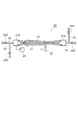
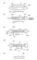
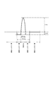
始めに、実施形態による光ファイバ母材の製造方法に好適に使用される加熱装置について説明する。図1は、実施形態による光ファイバ母材の製造方法に好適に使用される加熱装置を示す概略図である。加熱装置20は、ガラスパイプ11を回転可能に保持する回転継手21a,21bと、回転継手21aに接続されガラスパイプ11内へと所定のガスを供給するガス供給管22と、ガス供給管22の所定の位置から分岐するよう設けられた減圧管23と、ガラスパイプ11に供給されたガスを排気する排気管24と、排気管24に合流するように設けられた供給補助管25と、回転継手21aに接続されガラスパイプ11内の圧力をモニタする圧力ゲージ26と、減圧管23に接続された排気装置(図示せず)と、ガラスパイプ11とガラスロッド12とを加熱一体化する熱源27とから構成される。
【0025】
ガス供給管22にはバルブ22vが設けられており、減圧管23にはバルブ23vが設けられており、排気管24にはバルブ24vが設けられており、供給補助管25にはバルブ25vが設けられている。ガス供給管22からは、塩素(Cl2)ガス、六弗化硫黄(SF6)、窒素(N2)ガス、酸素(O2)ガス、又は不活性ガスなどをガラスパイプ11内へと供給できる。供給補助管25からは、Cl2ガス、N2ガス、O2ガス、又は不活性ガスを供給できる。実際に、ガラスパイプ11内にガスを供給する際には、バルブ22v〜25vが適宜開閉状態とされる。例えば、バルブ23v,25vを閉めるとともにバルブ22v,24vを開けると、ガス供給管22から、回転継手21a、ガラスパイプ11、及び回転継手21bへと経て、さらに排気管24を通して排気ガス処理設備(図示せず)へ所定のガスを流すことができる。また、バルブ22v,24v,25vを閉めるとともにバルブ23vを開けると、ガラスパイプ11内を真空引きできる。また、排気装置としてはアスピレータ或いはロータリーポンプ等を使用できる。熱源27は、回転継手21a,21bにより保持されるガラスパイプ11の長手方向に沿って移動可能に設けられている。熱源27としては、具体的には、酸水素火炎バーナを使用することができる。
【0026】
(第1の実施形態)
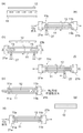
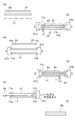
本発明に係る光ファイバ母材の製造方法の第1の実施形態について説明する。図2(a)〜(g)は、第1の実施形態の製造方法の工程と、各工程終了時又は工程実施中の光ファイバ母材を示す模式図である。
【0027】
(縮径部工程)
先ず、石英ガラス製のガラスパイプ11とガラスロッド12とを用意する(図2(a)) 。ガラスパイプ11及びガラスロッド12は、作製される光ファイバが有すべき特性を実現する所定の屈折率を有する。例えば、フッ素(F)が所定の濃度で添加された石英ガラスから成るガラスパイプと、塩素(Cl)が所定の濃度で添加された石英ガラスから成るガラスロッドと、であってよい。また、F添加石英ガラスからなるガラスパイプと、高純度石英ガラスからなるガラスロッドとでもよい。
【0028】
上記のガラスパイプ11及びガラスロッド12が用意された後、ガラスパイプ11の両端近傍に第1の縮径部11aと第2の縮径部11bとが以下のように形成される。先ず、ガラスパイプ11を所定の加熱装置20に取り付ける。その後、SF6ガスをガス供給管22からガラスパイプ11内に流しながら、熱源27によりガラスパイプ11を1500℃程度に加熱し、その内面をエッチングする。このとき、ガラスパイプ11を回転継手21a,21bにより回転させ、熱源27を一定の速度でSF6ガスの流れる方向に沿って数回移動させる。これにより、ガラスパイプ11の内面は均一にエッチングされ、ガラスパイプ11の内径を所望の値とできる。
【0029】
エッチング後のガラスパイプ11の内径及びガラスロッド12の外径は、ガラスパイプ11の内径を直径DPとし、ガラスロッド12の外径を直径dとしたときに、0.1≦ (DP−d)/2 ≦3(mm)といった関係を満たすと好ましい。(DP−d)/2で表される値が0.1mmより小さいと、ガラスロッド12をガラスパイプ11中へと挿入するのが困難となり、また、後の加熱一体化工程においてガラスパイプ11とガラスロッド12との間に気泡が形成され易くなる虞がある。また、この値が3mmより大きいと、後述する加熱一体化の際に、ガラスパイプ11を周方向に均一に収縮させることが難くなり、その結果、非円率及び偏芯率が増大してしまう。
【0030】
エッチング終了後、回転継手21a,21bを取り外して、ガラスパイプ11の両端の各々にダミーロッド13を挿入する。このダミーロッド13は、石英ガラスと溶融しない高融点セラミックといった材料から成ると好ましい。また、ダミーロッド13の外径(直径)は、ガラスロッド12の外径dより大きく、d+1(mm)以下であると好ましい。ダミーロッド13の挿入後、再び、回転継手21a,21bをガラスパイプ11に取り付け、ガラスパイプ11内の空気をCl2ガスで置換する。そして、ダミーロッド13のある位置において、ガラスパイプ11の一部を熱源27により加熱する(図2(b))。また、このとき、ガラスパイプ11を回転させ、その周囲に沿って温度がほぼ均一となるようにすると好ましい。これにより、ガラスパイプ11が周方向に均一に縮径される。内径がダミーロッド13の外径と等しくなるまでガラスパイプ11を縮径する。これにより、ガラスパイプ11の両端近傍に縮径部11a,11bが形成される。
【0031】
ここで、縮径部11a,11bの内径はガラスロッド12の外径よりも大きく、また、縮径部11a,11bの内径とガラスロッド12の外径との差は1mm以下であると好ましい。縮径部11a,11bの内径がガラスロッド12の外径以下であると、ガラスロッド12をガラスパイプ11内へ挿入できない。また、その差が1mmより大きいと、ガラスロッド12の中心軸とガラスパイプ11の中心軸とが一致し難くなってしまう。また、縮径部11a,11bの内径は、ガラスロッド12の外径よりも大きく、縮径部11a,11bの内径とガラスロッド12の外径との差が0.5以下であると更に好ましい。なお、縮径部11a,11bの内径は、縮径部11a,11b形成時にガラスパイプ11に挿入されるダミーロッド13の径を適宜調整することにより所望の値とすることができる。
【0032】
(挿入工程)
縮径部11a,11bの形成後、供給補助管25から回転継手21bを経てガラスパイプ11内へとN2ガス又は不活性ガスを流すとともに、回転継手21aを外す。この状態で、ガラスロッド12をガラスパイプ11内に挿入する(図2(c))。N2ガス又は不活性ガスを流しているため、ガラスパイプ11内への空気の流入を防止できる。
【0033】
(固定工程)
ガラスロッド12をガラスパイプ11内に挿入後、回転継手21aを取り付ける。このとき、挿入されたガラスロッド12は、図2(d)に示す通り、ガラスパイプ11に形成された縮径部11a,11bにより保持されている。その後、ガス供給管22からCl2ガスを所定流量で供給し、ガラスパイプ11内のN2ガス又は不活性ガスをCl2ガスで置換する。Cl2ガスを流したままガラスパイプ11及びガラスロッド12を回転させながら、縮径部11aを熱源27により加熱して、ガラスパイプ11とガラスロッド12とを溶融する。これにより、ガラスロッド12がガラスパイプ11に対して固定された固定縮径部11cが形成される(図2(e))。
【0034】
ここで、固定縮径部11cにおいては、ガラスロッド12の周囲全体をガラスパイプ11と溶融させることなく、所定の大きさの隙間が形成されていると好ましい。その理由は以下の通りである。固定縮径部11cにおいてガラスパイプ11とガラスロッド12とが周囲全体で溶融している場合は、加熱一体化中にガラスパイプとガラスロッドとの間隙部の気体(Cl2ガス)が外部へと流れ出ることができない。そのため、加熱一体化を進行に伴って間隙部の体積が減少していくと、間隙部内の圧力が上昇してしまう。その結果、ガラスパイプが膨張してしまう虞がある。したがって、ガラスロッド12はガラスパイプ11に対して部分的に固定され、隙間が残されると好ましい。このようにすれば、ガラスパイプ11とガラスロッド12との間の気体は隙間を通して外部へと放出されるため、ガラスパイプ11の膨張を防ぐことができる。その隙間の大きさは、加熱一体化に伴ってガラスロッド12とガラスパイプ11との間の空間が減少していく速度よりも速い速度で気体が通過できる程度であることが好ましい。具体的には、流量をV(mm3/min)、ガラスパイプ11の内径(直径)をrp(mm)、ガラスロッド12の外径(直径)をrr(mm)、熱源27の移動速度をυ(mm/min)とすると、
V≧{(rp/2)2×π−(rr/2)2×π)}× υ …(1)
といった関係を満たすと好適である。式(1)の右辺は、ガラスパイプ11とガラスロッド12との間隙部の体積が、後述する加熱一体化により、単位時間当りにどの程度減少するかを示す。したがって、この体積の減少分以上のガスをガラスパイプ11の外部に放出すれば、間隙部の圧力上昇を防止できる。
【0035】
(加熱一体化工程)
上記のような隙間を有する固定縮径部11cが形成された後、熱源27によりガラスパイプ11とガラスロッド12とを空焼きする。空焼き中には、固定縮径部11cの形成時と同様にCl2ガスを流す。Cl2ガスは、ガラスパイプ11の内部をその一方端から、固定縮径部11cに設けられた隙間を通って他方端へと流れる。また、空焼き中にはガラスパイプ11とガラスロッド12とは回転される。所定の時間空焼きを行った後、ガラスパイプ11とガラスロッド12とを回転させたまま、縮径部11bを加熱し、ガラスパイプ11とガラスロッド12とを周方向の全体に渡って一体化する。一体化されるとほぼ同時にガラスパイプ11の内部を所定の真空度にまで減圧する。この真空度としては、圧力ゲージ26の指示値にて−10〜−0.1kPa程度であると好ましい。なお、圧力ゲージ26の指示値は大気圧が0kPaであるため、例えば指示値−2kPaで示される圧力は大気圧よりも2kPa低い。以下の説明において、大気圧よりも2kPa低い圧力を圧力ゲージ26の指示値−2kPaと記す。ガラスパイプ11内が減圧された状態で、熱源27を縮径部11bから固定縮径部11cの方向へと動させながら、ガラスパイプ11を熱源27により加熱し、ガラスパイプ11とガラスロッド12とを加熱一体化する(図2(f))。以上により、第1の実施形態の光ファイバ母材10が得られる(図2(g))。
【0036】
上述の通り、第1の実施形態の光ファイバ母材の製造方法においては、ガラスロッド12は、ガラスパイプ11に形成された縮径部11a,11bによりガラスパイプ11内で保持されるので、ガラスロッド12の中心軸がガラスパイプ11の中心軸と一致される。また、固定縮径部11cにおいて、ガラスロッド12がガラスパイプ11に対して固定される。そして、固定されていない縮径部11bから固定縮径部11cの方向へと熱源27を移動させながらガラスロッド12とガラスパイプ11とを加熱一体化する。一般に、加熱一体化が行われているときには、ガラスロッド12とガラスパイプ11との溶融により、ガラスロッド12には溶融部へと引き込まれるような力が生じる。しかし、ガラスロッド12は、固定縮径部11cにおいてガラスパイプ11と固定されているため移動することはない。そのため、加熱一体化中のガラスロッド12の移動に伴って生じる偏芯等が防止され、光ファイバ母材の偏芯率及び非円率の低下が確実に抑止される。
【0037】
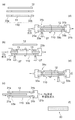
なお、以上の説明では、ガラスパイプ11の両端近傍に縮径部を形成した。しかし、ガラスパイプ11の両端に補助ガラスパイプを1本ずつ接続し、この補助ガラスパイプそれぞれに縮径部を形成するようにしてもよい。以下に、この場合の手順を図3(a)〜(f)を用いて説明する。先ず、ガラスパイプ11と内径及び外径がほぼ等しい補助ガラスパイプ33a,33bをそれぞれ1つずつ中心軸が一致するようにガラスパイプ11の両端に接続し、ガラスパイプ110を得る(図3(a))。次に、ガラスパイプ110内にSF6ガスを流す。その後、ガラスパイプ110を熱源27により1500℃程度に加熱し、その内面をエッチングする。このとき、補助ガラスパイプ33a,33bについても所定の長さに渡ってエッチングすると好ましい。続いて、縮径部31a,31bを形成する(図(b))。縮径部31a,31bの形成方法は、上述の縮径部11a,11bと同様である。また、縮径部31a,31bは補助ガラスパイプ33a,33bに設けられる。
【0038】
続いて、ガラスロッド12をガラスパイプ110内に挿入する(図3(c))。その後、縮径部31aにおいて、ガラスロッド12と補助ガラスパイプ33aとを溶融固定する(図3(d))。つまり、縮径部31aが固定縮径部31cとなる。溶融固定後、ガラスパイプ110及びガラスロッド12を回転させ、縮径部31bから固定縮径部31cへと向かう方向に熱源27を移動させながら、ガラスロッド12とガラスパイプ11とを加熱一体化する(図3(e))。これにより、光ファイバ母材30が得られる(図3(f))。このようにしても、ガラスロッド12は、ガラスパイプ11と互いの中心軸がほぼ一致するよう保持され、さらに固定縮径部11cにおいて固定される。したがって、光ファイバ母材のコア部非円率及びコア部偏芯率は確実に低下される。
【0039】
(第2の実施形態)
次に、本発明に係る光ファイバ母材の製造方法の第2の実施形態について説明する。図4(a)〜(h)は、第2の実施形態の製造方法の工程と、各工程終了時又は工程実施中の光ファイバ母材を示す模式図である。
【0040】
第2の実施形態は、ガラスロッドをガラスパイプに挿入する方法が異なる以外は、第1の実施形態とほぼ同一である。以下では、相違点を主として説明する。
【0041】
先ず、第1の実施形態で説明した手順とほぼ同様に、ガラスパイプ11に縮径部11a,11bを形成する(図4(a))。次に、予め用意した挿入保護管41にガラスロッド12を挿入する(図4(b))。この挿入保護管41は、ガラスロッド12が挿入できる内径とガラスパイプ11に挿入できる程度の外径とを有している。また、この挿入保護管41は、石英よりも硬度が低い材料から構成されると好適である。このような材料から構成されれば、ガラスロッド12をガラスパイプ11に挿入する際にガラスパイプ11及びガラスロッド12に傷がつき難い。具体的には、挿入保護管41はポリテトラフルオロエチレン(以下、テフロン(デュポン社の商標名))製であると好ましい。
【0042】
そして、内部にガラスロッド12が挿入された挿入保護管41を縮径部11a,11bが形成されたガラスパイプ11内へと挿入する(図4(c))。このときには、回転継手21b側からN2ガス又は不活性ガスをガラスパイプ11内に供給し、ガラスパイプ11内に空気が流入するのを防ぐ。その後、N2ガス又は不活性ガスを流した状態で、ガラスロッド12がガラスパイプ11内に残るように挿入保護管41を引き抜く(図4(d))。これにより、ガラスパイプ11内において、ガラスロッド12がガラスパイプ11の縮径部11a,11bに保持される(図4(e))。続いて、第1の実施形態と同様に、ガラスパイプ11とガラスロッド12とを一体化する(図4(g))。以上により、第2の実施形態の光ファイバ母材の製造方法による光ファイバ母材40が得られる(図4(h))。
【0043】
上述の通り、第2の実施形態の光ファイバ母材の製造方法においては、ガラスロッド12がテフロン製の挿入保護管41に挿入された状態でガラスパイプ11へと挿入される。その後、挿入保護管41だけが引き抜かれ、ガラスロッド12がガラスパイプ11内において縮径部により保持される。そして、縮径部の一方(固定縮径部11c)においてガラスロッド12がガラスパイプ11に対して固定される。そのため、第1の実施形態の製造方法と同様の効果が得られる。
【0044】
また、挿入保護管41の使用により、ガラスロッド12の挿入の際にガラスロッド12の外周及びガラスパイプ11の内周に傷がつくのを防止できる。ガラスロッド12の外周及びガラスパイプ11の内周とに傷がつくと、この傷自体、または、傷ができることにより生じるガラスの粒子により、加熱一体化後、ガラスロッド12とガラスパイプ11との間に気泡が残留してしまう虞がある。光ファイバ母材に気泡が残留してしまうと、この光ファイバ母材から作製される光ファイバの損失が増大してしまうという問題が生じる。また、作製される光ファイバの強度が低下してしまうという問題も生じる。テフロンといった石英よりも硬度の低い材料からなる挿入保護管41を使用すれば、傷を防ぐことができるため、傷に起因する気泡の発生を抑止できる。
【0045】
(第3の実施形態)
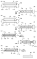
本発明に係る光ファイバ母材の製造方法の第3の実施形態について説明する。図5(a)〜(e)は、第3の実施形態の製造方法の工程と、各工程終了時又は工程実施中の光ファイバ母材を示す模式図である。
【0046】
第3の実施形態においては、ガラスパイプ11の一方の端部近傍に2つの縮径部が設けられる。この点を除くと、他の手順は第1の実施形態の製造方法とほぼ同一である。以下に、相違点を主として説明する。
【0047】
図5(a)に示す通り、ガラスパイプ11の一方の端部の近傍に2つの縮径部51a,51bと、他方の端部の近傍に1つの縮径部51cが設けられる。そして、このガラスパイプ11にガラスロッド12が挿入される(図5(b))。ここで、第2の実施形態と同様に、ガラスロッド12を挿入保護管41に挿入した状態でガラスパイプ11へと挿入し、挿入保護管41だけを引き抜くようにしても良い。
【0048】
縮径部51a,51bのうち、ガラスパイプ11の開放端部により近い縮径部51aにおいて、ガラスロッド12をガラスパイプ11に対して固定する(図5(c))。すなわち、縮径部51aが固定縮径部51dとして使用される。また、固定縮径部51dにおいては、ガラスロッド12とガラスパイプ11との間の気体が式(1)で表される流量Vで通過できる間隙が設けられると好適である。そして、ガラスロッド12の縮径部51cから縮径部51bへと向かう方向に熱源27を移動させながら、ガラスロッド12とガラスパイプ11とを加熱一体化する(図5(d))。これにより、第3の実施形態の製造方法による光ファイバ母材50が得られる(図5(e))。
【0049】
以上のように、第3の実施形態においては、ガラスパイプ11の一方の端部の近傍に2つ縮径部51a,51bが設けられる。ガラスロッド12をガラスパイプ11に挿入した後、縮径部51aにおいて、ガラスロッド12がガラスパイプ11に対して溶融固定される。その後、縮径部51cから縮径部51bへと熱源27を移動しながらガラスパイプ11とガラスロッド12とを加熱一体化していく。第3の実施形態による光ファイバ母材の製造方法においては、ガラスロッド12が縮径部51a,51b,51cによりガラスパイプ11と中心軸が一致するように保持され、しかも、縮径部51aにおいてガラスパイプ11に対し固定される。そのため、コア部非円率及びコア部偏芯率が低減された光ファイバ母材が得られる。
【0050】
また、第3の実施形態の光ファイバ母材の製造方法は、ガラスロッド12の軟化点温度が低い場合、又はガラスロッド12が比較的細い場合に特に効果的である。このような場合、ガラスロッド12をガラスパイプ11に対して溶融固定する際には、ガラスロッドが湾曲してしまう虞がある。また、ガラスロッド12をガラスパイプ11に対して溶融固定する際に、何らかの原因で熱源27温度が所定の温度よりも高くなってしまった場合にも、ガラスロッド12の湾曲が生じてしまう可能性がある。ガラスロッド12が湾曲してしまうと、ガラスロッド12が偏芯してしまい、その結果、偏芯率が増大してしまう。しかしながら、第3の実施形態によれば、固定縮径部51dにおいて湾曲が発生したとしても、ガラスロッド12は、固定縮径部51dに隣接する縮径部51bによって保持されるため、ガラスパイプ11と加熱一体化される部分(縮径部51bと51cとの間)においては偏芯してしまうことがない。その結果、光ファイバ母材50の偏芯率及び非円率が一層確実に低減される。
【0051】
(第4の実施形態)
本発明に係る光ファイバ母材の製造方法の第4の実施形態について説明する。図6(a)〜(f)は、第4の実施形態の製造方法の工程と、各工程終了時又は工程実施中の光ファイバ母材を示す模式図である。第4の実施形態は、ガラスロッドに補助ガラスロッドを接続する点を除き、第1の実施形態とほぼ同一である。以下に、相違点を主として説明する。
【0052】
先ず、光ファイバ母材製造用の原材料として、GeO2添加石英ガラスからなるガラスロッド61(以下、有効部ガラスロッド61と称する)とClが添加された石英ガラスからなるガラスパイプ11とが用意される。この有効部ガラスロッド61の少なくとも一方の端部に、高純度石英ガラスからなる補助ガラスロッド62が溶融接続される(図6(a))。補助ガラスロッド62は、有効部ガラスロッド61とほぼ等しい外径を有し、その中心軸が有効部ガラスロッド61の中心軸と一致するように接続される。
【0053】
続いて、ガラスパイプ11の両端近傍に縮径部11a,11bがそれぞれ形成される(図6(b))。この形成方法は、第1の実施形態における縮径部形成方法と同一である。ただし、第3の実施形態の製造方法と同様にガラスパイプ11の一方の端部に2つの縮径部を設けるにしてもよい。次に、補助ガラスロッド62が接続された有効部ガラスロッド61がガラスパイプ11内へ挿入される(図6(c))。このとき、第2の実施形態の製造方法と同様に挿入保護管41を用いてもよい。そして、補助ガラスロッド62をガラスパイプ11の縮径部11aに対して固定される(6(d))。すなわち、縮径部11aが固定縮径部11cとなる。この後、第1の実施形態と同様の方法により、ガラスパイプ11と有効部ガラスロッド61とが加熱一体化される(図6(e))。以上の手順により、光ファイバ母材60が得られる(図6(f))。
【0054】
上述の通り、第4の実施形態の光ファイバ母材の製造方法においては、高純度石英ガラスからなる補助ガラスロッド62が有効部ガラスロッド61の一方の端部に溶融接続される。この補助ガラスロッド62を有する有効部ガラスロッド61がガラスパイプ11に挿入される。そして、ガラスパイプ11に形成された縮径部11aが固定縮径部11cとして利用され、固定縮径部11cにおいて補助ガラスロッド62がガラスパイプ11に対して溶融固定される。すなわち、この固定縮径部11cにおいては、Cl添加石英ガラスと高純度石英ガラスとが互いに固定されることになる。このようにしても、有効部ガラスロッド61は、その中心軸がガラスパイプ11の中心軸と一致するように保持されるため、第1の実施形態による光ファイバ母材の製造方法と同様の効果が得られる。
【0055】
また、第4の実施形態による光ファイバ母材の製造方法は、以下の効果を奏する。Cl添加石英ガラスからなるガラスパイプ11とGeO2添加石英ガラスからなる有効部ガラスロッド61とが直接溶融により固定されると、固定部にはマイクロクラックが多数発生してしまう事態となる。これは、石英ガラス中に添加されたGeO2の周囲には局所的な歪が発生していることから生じる。すなわち、有効部ガラスロッド61が加熱・冷却されると、本来存在する歪に熱膨張による応力が加わり、マイクロクラックが発生してしまう。マイクロクラックが発生すると、ガラスパイプ11と有効部ガラスロッド61との加熱一体化時に、有効部ガラスロッド61がガラスパイプ11から外れ易くなってしまう虞がある。
【0056】
一方、第4の実施形態の製造方法では、ガラスパイプ11の縮径部11aにおいて、有効部ガラスロッド61に接続された高純度石英ガラス製の補助ガラスロッド62とCl添加石英ガラスからなるガラスパイプ11とが互いに固定される。高純度石英ガラスとCl添加石英ガラスとであれば、マイクロクラックが発生することはないので、両者は確実に固定される。そのため、加熱一体化中に、補助ガラスロッド62が外れてしまうのを確実に防ぐことができる。したがって、有効部ガラスロッド61の移動により生じる非円率又は偏芯率の増大を確実に抑止できる。
【0057】
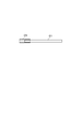
以上の説明では、補助ガラスロッド62を有効部ガラスロッド61に接続した。しかし、図7に示すように、補助ガラスパイプ63を用い、これを有効部ガラスロッド61に嵌め込むようにしてもよい。補助ガラスパイプ63は、高純度石英ガラス又はF、P若しくはClが添加された石英ガラスからなると好ましい。石英ガラス中にF、P、又はClが添加されていても、これらの添加物に起因する局所的な歪が生じない。そのため、これらが添加された石英ガラスを補助ガラスパイプ63として使用しても、マイクロクラックが発生することはない。また、補助ガラスパイプ63の内径は有効部ガラスロッド61の外径よりも僅かに大きいと好ましい。このようにすれば、有効部ガラスロッド61を補助ガラスパイプ63の内部に挿入することのみにより、有効部ガラスロッド61と補助ガラスパイプ63とが互いに固定され得る。このような固定方法は、以下の利点を有する。
【0058】
有効部ガラスロッド61の軟化点温度は、GeO2の添加により低くなる。有効部ガラスロッド61のGeO2濃度が比較的高い場合に、例えば、上述した補助ガラスロッド62を有効部ガラスロッド61に溶融接続すると、有効部ガラスロッド61が湾曲してしまう虞がある。しかし、補助ガラスロッド62に替わり、補助ガラスパイプ63を用い、しかも、補助ガラスパイプ63内に有効部ガラスロッド61を挿入することにより互いに固定するようにすれば、有効部ガラスロッド61が湾曲してしまうことはない。すなわち、有効部ガラスロッドに補助ガラスパイプを接続する上記の方法は、GeO2濃度が比較的高い有効部ガラスロッドを用いる場合に特に好適である。また、ガラスロッドが比較的細く湾曲し易い場合にも好適に適用され得る。
【0059】
また、補助ガラスパイプ63を用いる場合には、有効部ガラスロッド61は、その外径が端部近傍の所定の位置から端部に向かって漸次減少していくテーパ部を有すると好ましい。このようにすれば、有効部ガラスロッド61と補助ガラスパイプ63とを確実に接続できる。また、このようにすれば、補助ガラスパイプ63の外径を有効部ガラスロッド61の外径とほぼ同一とした場合でも有効部ガラスロッド61を補助ガラスパイプ63に挿入し得る。したがって、補助ガラスパイプ63が接続された有効部ガラスロッド61をクラッド部となるべきガラスパイプに挿入するのが容易になる。
【0060】
以下に、本発明による光ファイバ母材の製造方法について実施例を用いて詳細に説明する。
【0061】
(実施例1)
実施例1においては、(A)光ファイバ母材のクラッド部となるべきガラスパイプの両端に1本ずつ補助ガラスパイプを接続し、(B)2本の補助ガラスに1つずつ縮径部を形成し、(C)光ファイバ母材のコア部となるべきガラスパイプを上記のガラスパイプ内に挿入し、(D)縮径部の一方(固定縮径部)において、ガラスロッドをガラスパイプに対して固定し、(E)他方の縮径部から固定縮径部へと熱源27を移動しながらガラスパイプとガラスロッドとを加熱一体化することにより光ファイバ母材を作製した。
【0062】
以下、実施例1について詳細に説明する。始めに、ガラスパイプとガラスロッドとを用意した。このガラスパイプは、Fが1.3mol%添加された石英ガラスから作製され、内径11mm、外径30mm、長さ450mmを有する。また、ガラスロッドは、Clが0.3mol%添加された石英ガラスから作製され、外径8mm、長さ550mmを有する。次に、上記のガラスパイプの両端に、加熱装置20の熱源等を用いて、補助ガラスパイプを1本ずつ溶融接続した。この補助ガラスパイプは、高純度石英ガラスから作製され、ガラスパイプとほぼ同一の内外径を有する。また、補助ガラスパイプの長さは、500mm程度である。接続の際には、ガラスパイプの中心軸と補助ガラスパイプの中心軸とが一直線状に繋がるよう軸合せを行った。
【0063】
続いて、補助ガラスパイプが接続されたガラスパイプを回転継手21a,21bにより回転させた。そして、当該ガラスパイプ内にSF6ガスを流すとともに、熱源27によりこのガラスパイプを1500℃程度に加熱してその内面をエッチングした。エッチング後、2つの補助ガラスパイプ内に外径8.5mmのセラミック製のロッドをそれぞれ挿入した。そして、補助ガラスパイプが接続されたガラスパイプを回転させながら、それぞれの補助ガラスパイプの一部を熱源27により周方向に均一に加熱した。縮径部の内周面がセラミック製のロッドと周方向の全体に渡って接した時点で加熱を停止した。以上により、補助ガラスパイプの各々に内径が8.5mmの縮径部が形成された。
【0064】
次に、縮径部を有するガラスパイプに上記のガラスロッドを挿入した。このとき、ガラスパイプの端部のうち、ガラスロッドを挿入する端部と反対側の端部からN2ガスを流し、ガラスパイプ内に空気が流れ込むのを防ぐようにした。挿入されたガラスロッドは、ガラスパイプに設けられた縮径部に保持されていた。次に、ガラスパイプ内へとCl2ガスを供給した。ガラスパイプ内のN2ガスがCl2ガスで置換された後、ガラスパイプと及びガラスロッドを回転させた。続いて、縮径部の一方を補助ガラスパイプの外側から熱源27を用いて加熱することにより、ガラスロッドを縮径部(固定縮径部)に対して固定した。このとき、固定縮径部には、式(1)を満たす流量VでCl2ガスが通過できる隙間を設けた。この後、Cl2ガスを所定の流量で流すとともに、ガラスパイプを加熱して空焼きを行った。空焼き終了後、ガラスパイプ内に流すCl2ガスの流量を3.0×105mm3/min程度とし、ガラスパイプ及びガラスロッドを回転させた状態で、固定縮径部とは反対側の縮径部を加熱した。この縮径部においてガラスパイプとガラスロッドとが周方向の全体に渡って加熱一体化されるとほぼ同時に、ガラスパイプ内の圧力が圧力ゲージの指示値で−2kPaとなるよう排気装置により真空引きした。その後、熱源27を固定縮径部の方へと30mm/minで移動させながらガラスロッドとガラスパイプとを一体化した。このとき、熱源27により加熱されたガラスパイプの表面温度は1620℃程度であった。
【0065】
以上により、実施例1の光ファイバ母材が得られた。この光ファイバ母材を、説明の便宜上、光ファイバ母材1Aと記す。続いて、この光ファイバ母材1Aの長手方向に沿う複数の測定点において、プリフォームアナライザ等を用いてコア部非円率とコア偏芯率とを測定した。その結果、いずれの測定点においても、コア部非円率は0.1〜0.4%であり、コア偏芯率は0.1〜0.5%であった。
【0066】
ここで、コア部非円率は、コア部の径方向の断面形状を楕円近似し、得られた楕円の長径2amaxと短径2aminとを用い、(2amax−2amin)/2amax×100(%)により定義される。また、コア偏芯率は、図8に示す通り、光ファイバ母材断面において、コア部の中心とクラッド部の外周との距離の最大値dmax及び最小値dminに対して、(dmax−dmin)/(dmax+dmin)×100(%)により定義される。
【0067】
また、実施例1と比較するため、比較例1Sとして、上記の手順(A)、(B)、及び(C)を順次実施した後、手順(D)を行なわずにガラスロッドとガラスパイプとを加熱一体化して光ファイバ母材を作製した。作製に使用したガラスロッド、ガラスパイプ、及び補助ガラスパイプ、さらに加熱条件等は実施例1とほぼ同一とした。比較例1Sにおいて作製した光ファイバ母材を光ファイバ母材1Sとする。光ファイバ母材1Sの長手方向に沿う複数の測定点において、プリフォームアナライザを用いてコア部非円率とコア偏芯率とを測定した。その結果、いずれの測定点においても、コア部非円率は1.5〜2.5%であり、コア偏芯率は3〜10%であった。
【0068】
さらに、光ファイバ母材1A,1Sと比較するため、比較例1Tとして、上記の手順(A)及び(C)を順次実施した後、ガラスパイプとガラスロッドとを加熱一体化して光ファイバ母材を作製した。作製に使用したガラスロッド、ガラスパイプ、及び補助ガラスパイプ、さらに加熱条件等は実施例1とほぼ同一とした。比較例1Tにおいて作製した光ファイバ母材を光ファイバ母材1Tとする。光ファイバ母材1Tについてコア部非円率とコア偏芯率との測定を行なったところ、長手方向に沿う複数の測定点において、コア部非円率は1.8〜4.2%といった値であり、コア偏芯率は17〜20%といった値であった。光ファイバ母材1A,1S,1Tを比較すると、光ファイバ母材1Aは、光ファイバ母材1S,1Tよりもコア部非円率とコア偏芯率との点で優れることが分かる。
【0069】
(実施例2)
実施例2は、上述の第2の実施形態に対応する。すなわち、実施例2においては、ガラスロッドは、テフロン製の挿入保護管に挿入された後、ガラスロッドに挿入される。その後、挿入保護管のみを引き抜くと、ガラスロッドがガラスパイプの縮径部に保持される。以下、詳しい手順を説明する。
【0070】
先ず、ガラスパイプ及びラスロッドを用意した。このガラスパイプは、Fが1.3mol%添加された石英ガラスから作製され、内径9mm、外径30mm、長さ400mmを有する。また、ガラスロッドは、塩素が0.3mol%添加された石英ガラスから作製され、外径8mm、長さ450mmを有する。次に、ガラスパイプを加熱装置に取り付けた。続けて、ガラスパイプを回転させ、ガラスパイプ内にSF6ガスを供給した。当該ガラスパイプを熱源27により1500℃程度の温度に加熱し、その内面をエッチングした。その後、上記のガラスパイプの両端部の近傍において、実施例1とほぼ同様の手順により、内径が8.5mmの縮径部をガラスパイプの端部近傍に形成した。
【0071】
次に、上記のガラスロッドをテフロン製の挿入保護管に挿入した。この挿入保護管の内径は8.1mmであり、外径は8.4mmである。その後、ガラスロッドが挿入された挿入保護管を、縮径部を有するガラスパイプ内に挿入した。挿入保護管をガラスパイプに挿入した後、挿入保護管だけを引き抜いた。挿入保護管を引き抜いた後には、ガラスロッドは、ガラスパイプに設けられた縮径部により保持されていた。
【0072】
その後、Cl2ガスを流すとともに、ガラスパイプ及びガラスロッドを回転させ、縮径部の一方をガラスパイプの外側から熱源27を用いて加熱することにより、ガラスロッドを縮径部(固定縮径部)に対して固定した。また、固定縮径部には、式(1)を満たす流量VでCl2ガスが通過できる隙間を設けた。続いて、Cl2ガスを流しながら、熱源27によりガラスパイプを外側から加熱して空焼きを行って、ガラスパイプ内を清浄化した。空焼き後、Cl2ガスの流量を3.0×105mm3/minとし、ガラスパイプ及びガラスロッドの回転数を所定の値とし、固定縮径部と反対側の縮径部を熱源27により加熱し、この縮径部において、ガラスパイプとガラスロッドとを一体化した。両者が一体化されると同時に、ガラスパイプ内の圧力が圧力ゲージの指示値で−7kPaとなるよう排気装置により調整した。さらに熱源27を固定縮径部の方へと30mm/minで移動させながらガラスロッドとガラスパイプとを一体化した。このとき、熱源27により加熱されたガラスパイプの表面温度は1550℃程度であった。
【0073】
以上により、光ファイバ母材が得られた。説明の便宜上、この光ファイバ母材を光ファイバ母材2Aと記す。プリフォームアナライザ等を用いて測定を行った結果、光ファイバ母材2Aの外径(直径)は29mm程度であり、そのコア部の外径は8mm程度であることが分かった。また、光ファイバ母材2Aの内部には気泡は全く認められなかった。続いて、この光ファイバ母材2Aの外周面に、Fが1.3mol%添加された石英ガラスをジャケット付けした。このようにして、クラッド径/コア径比12.7を有する光ファイバプリフォーム20Aを得た。その後、この光ファイバプリフォーム20Aを線引きし、外径が125μmである光ファイバを作製した。この光ファイバの伝送損失を測定したところ、波長1550nmにおいて0.165dB/kmという値が得られた。
【0074】
比較のため、比較例2Sとして、上記のテフロン製の挿入保護管に替わり石英ガラス製の挿入保護管を用いることを試みた。使用した石英ガラス製の挿入保護管の内径は8.1mmであり、外径は8.4mmであった。挿入保護管の材料が異なる点を除き実施例2と同様の手順により光ファイバ母材2Sを作製した。光ファイバ母材2S内部の気泡の数を測定したところ、300mmに平均2個程度であった。続いて、光ファイバ母材2Sの外周部にジャケット付けし、光ファイバプリフォーム20Aと同様にクラッド径/コア径比12.7を有する光ファイバプリフォーム20Sを作製した。その後、光ファイバプリフォーム20Sを線引きしてクラッド領域の外径が125μmである光ファイバを作製した。この光ファイバの伝送損失を測定した結果、波長1550nmにおいて0.165dB/kmという値が得られた。
【0075】
更なる比較のため、比較例2Tとして、挿入保護管を使用しない点を除き実施例2と同様の手順により光ファイバ母材2Tを作製した。光ファイバ母材2T内部の気泡の数を測定したところ、300mmにつき平均6個程度であった。続いて、光ファイバ母材2Tの外周部にジャケット付け、光ファイバプリフォーム20Tを作製した。光ファイバプリフォーム20Tを線引きしてクラッド領域の外径が125μmとなるよう光ファイバを作製した。この光ファイバの伝送損失を測定した結果、波長1550nmにおいて0.175dB/kmという値が得られた。
【0076】
以上のように、挿入保護管を使用しない場合でも実用上十分に低い伝送損失が得られるが、挿入保護管を使用すれば更に伝送損失を低減できる。これは、挿入保護管の使用により、ガラスロッド又はガラスパイプに傷がつき難くなり、しかも、ガラスの粒子等の発生もないためであると考えられる。すなわち、傷やガラス粒子等があるとこれらが核となり気泡が発生し易くなるが、挿入保護管の使用により、傷やガラス粒子等の発生を抑えられるので、気泡の数を減少できる。光ファイバ母材に気泡が発生すると、その光ファイバ母材から製造される光ファイバの機械的強度は著しく低下してしまう。本実施例によれば、気泡の発生を低減できるので、製造される光ファイバの機械的強度の低下を防止できる。
【0077】
(実施例3)
実施例3は、第1の実施形態に対応する。また、比較のため、比較例3S〜3Uとして式(1)を満たさない条件において光ファイバ母材の作製を行なった。
【0078】
実施例3の光ファイバ母材を作製するにあたり、先ず、ガラスパイプとガラスロッドとを用意した。ガラスパイプは、Fが1.3mol%添加された石英ガラスから作製され、内径(直径)6mm程度、外径(直径)35mm程度、及び長さ300mm程度を有する。また、ガラスロッドは、高純度石英ガラスから作製され、外径(直径)4mm程度及び長さ350mm程度を有する。
【0079】
上記のガラスパイプの両端部近傍に内径(直径)が4.3mmの縮径部を1つずつ形成した。この手順は、実施例1における縮径部形成手順とほぼ同一とした。縮径部形成後、上記のガラスロッドをガラスパイプ内へと挿入した。縮径部の一方(固定縮径部)を加熱することにより、ガラスロッドをガラスパイプに固定した。このとき、後述する加熱一体化の条件において、ガラスパイプとガラスロッドとの間に存在するガスが480mm3/min程度の流量で通過できるような隙間を固定縮径部に設けた。
【0080】
続いて、実施例1とほぼ同様の手順により、ガラスパイプとガラスロッドとを加熱一体化して、光ファイバ母材3Aを製造した。ただし、ガラスパイプ内へ供給するCl2ガスの流量を2.0×105mm3/minとした。また、加熱一体化中、ガラスパイプ内の圧力を圧力ゲージ26の指示値にて−4kPaとなるよう調整した。加熱一体化時のガラスパイプの温度は1550℃であった。作製された光ファイバ母材3Aについて外観検査を行なったところ、異常は認められず良好な母材が得られたことがわかった。
【0081】
比較例3Sとして、ガラスロッドをガラスパイプに固定する際に固定縮径部に所定の大きさの隙間を設けた。この隙間は、実施例3と同一の加熱一体化条件でガラスパイプとガラスロッドとを加熱一体化する際に、ガラスパイプとガラスロッドとの間に存在するガスが405mm3/min程度の流量で通過できるような大きさを有する。このようにして光ファイバ母材3Sを作製したが、加熱一体化中にガラスパイプの一部が膨張してしまい、光ファイバ母材3Sには比較的大きな気泡が生じていた。
【0082】
比較例3Tでは、固定縮径部に更に異なる大きさの隙間を設けた。この隙間は、実施例3と同一の条件で加熱一体化する際に、ガラスパイプとガラスロッドとの間に存在するガスが197mm3/min程度の流量で通過できるような大きさを有する。比較例3Uでは、109mm3/min程度の流量で通過できるような隙間を固定縮径部に設けた。比較例3T及び3Uにおいては、加熱一体化中にガラスパイプが膨張してしまった。その結果、加熱一体化を継続できない事態となり、光ファイバ母材の製造を中止せざるを得なかった。
【0083】
上述した通り、実施例3及び比較例3S〜3Uで用いたガラスパイプの縮径部以外の部分での内径(直径)は約6mmであり、ガラスロッドの外径(直径)は約4mmである。これらの値から式(1)の右辺を計算すると471mm3/minという流量値が得られる。すなわち、実施例3及び比較例3S〜3Uのなかでは、実施例3の光ファイバ母材3Aのみが式(1)を満たすよう作製された。実施例3及び比較例3S〜3Uで得られた結果から、上記の式(1)を満たす条件で作製された場合、良好な光ファイバ母材が得られることがわかる。
【0084】
(実施例4)
実施例4においては、光ファイバ母材のクラッド部となるべきガラスパイプ(以下、有効部ガラスパイプ)の両端のそれぞれに1本ずつ接続された補助ガラスパイプのうち、一方の補助ガラスに2つの縮径部が形成される点を除き、実施例1とほぼ同一の手順により、光ファイバ母材を作製した。以下に、相違点を中心として、実施例4について説明する。
【0085】
先ず、有効部ガラスパイプと、ガラスロッドと、2本の補助ガラスパイプとを用意した。有効部ガラスパイプは、Clが0.2mol%添加された石英ガラスからなり、外径が25mmである。ガラスロッドは、Fが1.5mol%添加された石英ガラスからなり、外径が3mmである。また、補助ガラスパイプは、高純度石英ガラスからなり、有効部ガラスパイプと外径及び内径がほぼ等しい。次に、有効部ガラスパイプの両端部に補助ガラスパイプを1本ずつ溶融接続した。この接続に際しては、有効部ガラスパイプと補助ガラスパイプとの中心軸を互いに一致させた。
【0086】
続いて、補助ガラスパイプが接続された有効部ガラスパイプを加熱装置20に取り付けた。これらのパイプを回転させるとともに、その内部にSF6ガスを流した。そして、熱源27により、これらのパイプを1500℃程度に加熱して内面をエッチングし、有効部ガラスパイプの内径を6mmとした。続いて、有効部ガラスパイプに接続された補助ガラスパイプの一方に縮径部を2つ形成した。他方の補助ガラスパイプには縮径部を1つ形成した。ここで、縮径部の内径はいずれも約3.5mmとした。縮径部の形成後、補助ガラスパイプが接続された有効部ガラスパイプ内にガラスロッドを挿入した。
【0087】
補助ガラスパイプが接続された有効部ガラスパイプ内にCl2ガスを流し、ガラスロッドを補助ガラスパイプに対して溶融固定した。ここで、ガラスロッドが補助ガラスパイプに固定された固定縮径部は、2つの縮径部が形成された補助ガラスパイプにおける開放端部に近い縮径部である。また、固定の際、ガラスパイプの表面温度は1550℃であった。固定縮径部を観察したところ、固定縮径部においてガラスロッドは湾曲していた。この原因は、(1)ガラスロッドの外径は上述の通り3mmと比較的細いこと、(2)ガラスロッドにFが添加されているため、軟化温度がガラスパイプよりも低いこと、にあると本発明者らは考えている。しかし、湾曲した部分は固定縮径部とこれと隣接する縮径部との間に限られており、この隣接する縮径部とガラスパイプの反対側の縮径部との間、特に有効部ガラスパイプ内にある部分ではガラスロッドの湾曲は認められず、有効部パイプとガラスロッドとの中心軸はほぼ一致していた。
【0088】
続いて、実施例1とほぼ同様の手順により、ガラスパイプとガラスロッドとを加熱一体化して光ファイバ母材4を得た。ただし、ここでは、Cl2ガスの流量を3.0×105mm3/minとし、加熱一体化中のガラスパイプ内の圧力を−1.5kPa(圧力ゲージの指示値)とした。光ファイバ母材4の外径は23.9mmであった。次に、光ファイバ母材4の長手方向に沿った数箇所の測定点においてコア部非円率を測定した。その結果、光ファイバ母材4のコア部非円率は0.1〜0.2%といった良好な値であることが確認された。
【0089】
比較のため、縮径部を補助ガラスパイプに1つずつ設けることとし、他の手順及び条件は実施例4と同一として光ファイバ母材4Sを作製した。光ファイバ母材4Sのコア部非円率は、1.5〜2.2%であった。以上の結果から、実施例4の効果が理解される。
【0090】
(実施例5)
実施例5では、Clが0.2mol%添加された石英ガラスからなり、内径が6mmであり、外径が25mmであるガラスパイプ(以下、有効部ガラスパイプ)と、GeO2が10mol%添加された石英ガラスからなり、外径が3mmであるガラスロッド(以下、有効部ガラスロッド)とを使用した。
【0091】
さらに、有効部ガラスパイプの端部への補助ガラスパイプの接続の有無、及び、有効部ガラスロッドの端部への補助ガラスロッドの接続の有無により、以下の組み合わせのガラスパイプとガラスロッドを用いて光ファイバ母材を作製した。
(a)実施例5A:高純度石英ガラス製の補助ガラスパイプが接続された有効部ガラスパイプと、高純度石英ガラス製の補助ガラスロッドが接続された有効部ガラスロッド。
(b)実施例5B:高純度石英ガラス製の補助ガラスパイプが接続された有効部ガラスパイプと、Fが1mol%添加された石英ガラス製の補助ガラスロッドが接続された有効部ガラスロッド。
(c)実施例5C:補助ガラスパイプの接続のない有効部ガラスパイプと、高純度石英ガラス製の補助ガラスロッドが接続された有効部ガラスロッド。
【0092】
実施例5A〜5Cにおいて、補助ガラスパイプを有効部ガラスパイプに接続した場合には、補助ガラスパイプに縮径部を形成した。また、実施例4と同様に、補助ガラスパイプの一方、又、補助ガラスパイプを用いていない場合は有効部ガラスパイプの一方の端部の近傍に2つの縮径部を設けた。この2つの縮径部のうち開放端部により近い縮径部にてガラスロッドとガラスパイプとを溶融固定した。固定時の補助ガラスパイプ表面の温度は、実施例5Aでは1400℃とし、実施例5B及び5Cでは1350℃とした。また、加熱一体化の手順及び条件については上述の実施例1とほぼ同一とし、実施例5Aの光ファイバ母材5A、実施例5Bの光ファイバ母材5B、及び光ファイバ母材5Cを製造した。
【0093】
光ファイバ母材5A〜5Cについてコア部非円率を測定したところ、光ファイバ母材5Aでは0.2〜0.6%であり、光ファイバ母材5B及び5Cではともに0.1〜0.3%であった。この結果から、いずれの場合も良好なコア部非円率を有する光ファイバ母材が得られたことがわかる。特に、光ファイバ母材5B及び5Cは、光ファイバ母材5Aに比べ低いコア部非円率が得られている。このような結果は、本発明者らは、固定縮径部における石英ガラスの融点の相違に起因すると推測している。すなわち、上述の通り、光ファイバ母材5Aでは、ガラスロッドとガラスパイプとは固定縮径部において互いに高純度石英ガラスである。これに対し、光ファイバ母材5Bでは、高純度石英ガラス(補助ガラスパイプ)とF添加石英ガラス(補助ガラスロッド)とである。さらに、光ファイバ母材5Cでは、Cl添加ガラスパイプ(有効部ガラスロッド)と高純度ガラスロッド(補助ガラスロッド)とである。すなわち、光ファイバ母材5B及び5Cの場合には、光ファイバ母材5Aの場合に比べ、ガラスロッドをガラスパイプに溶融固定する際の加熱温度を低くすることができる。溶融温度が低いほど、ガラスロッドには変形が起こり難くなると考えられる。そのため、光ファイバ母材のコア部非円率が低くなると考えることができる。
【0094】
上記実施例5A〜5Cと比較するため、上記の有効部ガラスパイプの端部に高純度石英ガラス製の補助ガラスパイプを接続したガラスパイプ、及び上記の有効部ガラスロッド(GeO2が10mol%添加された石英ガラス製)を使用し、実施例5Aとほぼ同一の作製手順及び条件にて光ファイバ母材5Sの作製を試みた。しかしながら、加熱一体化中に、有効部ガラスロッドが固定縮径部から外れてしまうという事態が生じた。同様の作製を3回試みたが、3回とも有効部ガラスロッドが固定縮径部から外れてしまった。外れた場合にも敢えて加熱一体化を継続して行い、光ファイバ母材5Sを製造した。光ファイバ母材5Sのコア部非円率を測定したところ、2.0〜3.2%という値が得られた。
【0095】
加熱一体化中には、加熱部において、ガラスロッドとガラスパイプとが溶融しているため、ガラスロッドには溶融部に向かって引き込まれるような力が働く。よって、ガラスロッドは、固定縮径部から外れてしまうと、溶融部に向かって移動してしまうこととなる。このような移動が起こると、ガラスロッドの偏芯が生じ、その結果、コア部非円率が増大してしまう。また、有効部ガラスロッドが固定縮径部から外れてしまう原因として、本発明者らは、GeO2添加石英ガラスからなる有効部ガラスロッドの場合には、固定縮径部において大きな歪みが生じてしまい、この歪みにより多数のマイクロクラックが発生したものと考えている。マイクロクラックの発生により、ガラスロッドがガラスパイプから外れてしまったと考えることができる。
【0096】
(実施例6)
実施例6では、Clが0.2mol%添加された石英ガラスからなり、内径が7mmであり、外径が30mmであるガラスパイプ(以下、有効部ガラスパイプ)と、GeO2が10mol%添加された石英ガラスからなり、外径が4mmであるガラスロッド(以下、有効部ガラスロッド)とを使用した。これらを2本ずつ用意した。また、有効部ガラスパイプ2本のそれぞれの両端には、有効部ガラスパイプと内径、外径、及び肉厚がほぼ等しく、高純度石英ガラスからなる補助ガラスパイプを接続した。補助ガラスパイプの一方に2つの縮径部を形成し、他方に1つの縮径部を形成した。縮径部の内径は、2本のガラスパイプのうち一方では4.5mmであり、他方では5.0mmとした。
【0097】
続いて、実施例4における製造手順とほぼ同一な手順により、光ファイバ母材を製造した。加熱一体化時の主な条件は、具体的には、Cl2ガス供給量3.0×105mm3/min、O2ガス供給量3.0×105mm3/min、熱源27の移動速度30mm/minとした。また、加熱一体化時のガラスパイプの温度は、1570℃とした。説明の便宜上、縮径部の内径が4.5mmであるガラスパイプから製造した光ファイバ母材を光ファイバ母材6Aとし、縮径部の内径が5.0mmであるガラスパイプから製造した光ファイバ母材を光ファイバ母材6Bと記す。
【0098】
比較のため、光ファイバ母材6A及び6Bの製造に用いたのとほぼ同一のガラスパイプ、ガラスロッド、及び補助ガラスパイプを2組用意した。有効部ガラスパイプの両端に補助ガラスパイプを1本ずつ形成した。その後、光ファイバ母材6A及び6Bの製造時と同様に、補助ガラスパイプに縮径部を設けた。ただし、内径は、一方のガラスパイプにおいては5.5mmであり、他方では6.0mmとした。その後、光ファイバ母材6A及び6Bを製造したのと同様の製造手順及び条件により、光ファイバ母材6S及び6Tを作製した。
【0099】
図9は、製造した光ファイバ母材6A,6B,6S,6Tについて測定したコア部非円率を示すグラフである。同図から分かるように、光ファイバ母材6Aでは0.2〜0.4%、光ファイバ母材6Bでは0.3〜0.8%といった値が得られ、ともに良好であることがわかる。また、縮径部の内径を5.5mmとして製造した光ファイバ母材6Sのコア部非円率は0.8〜1.2%であり、比較的良好な0.8%といった値も得られたものの、コア部非円率はやや高くなる傾向が見られた。また、縮径部の内径を6.0mmとして製造した光ファイバ母材6Sでは、そのコア部非円率は1.0〜1.5%と比較的高い値であった。
【0100】
以上の結果から、縮径部の内径を4.5mm(光ファイバ母材6A)及び5.0mm(同6B)とした場合に特に良好な非円率が得られることが分かる。すなわち、縮径部の内径とガラスロッド外径との差が1mm以下であると特に好適である。また、この差が1mmよりも大きい場合には、ガラスロッドをガラスパイプに挿入したときにガラスロッド及びガラスパイプの中心軸が互いに一致し難くなってしまうため、コア部非円率の値が大きくなる傾向が現れると本発明者らは考えている。また、縮径部の内径がガラスロッドの外径以下であると、ガラスロッドをガラスパイプ内へと挿入できないことは言うまでもない。
【0101】
(実施例7)
実施例7では、ガラスパイプとして、Fが1.1mol%添加された石英ガラスからなり、外径が25mmであるガラスパイプ(以下、有効部ガラスパイプ)を5本用意した。ここで、この5本の有効部ガラスパイプの内径は、以下の表1の「内径」の欄に示す通り、6.3〜11.7mmの範囲でそれぞれ異なる。また、これらの有効部ガラスパイプと組み合わせて使用されるガラスロッドとして、GeO2が27mol%添加された石英ガラスからなり、外径が6.1mmであるガラスロッド(以下、有効部ガラスロッド)を5本用意した。
【0102】
有効部ガラスパイプの両端には、高純度石英ガラスからなり、内径が8mmであり、外径が25mmである補助ガラスパイプを接続した。この接続の際には、補助ガラスパイプ及び有効部ガラスパイプのそれぞれの中心軸をほぼ一致させた。補助ガラスパイプの一方に2個の縮径部を形成し、他方には1個の縮径部を形成した。縮径部の形成の後、補助ガラスパイプが接続された有効部ガラスパイプ内へ有効部ガラスパイプを挿入した。その後、図1に示す加熱装置において、回転継手を補助ガラスパイプの双方にそれぞれ接続することにより、補助ガラスパイプが接続された有効部ガラスパイプを当該加熱装置に取り付けた。2個の縮径部を形成した補助ガラスパイプにおいて、この2個の縮径部のうち補助ガラスパイプの開放端部に近い縮径部で有効部ガラスロッドと補助ガラスパイプとを溶融固定した。有効部ガラスロッドと補助ガラスパイプとを固定した後、有効部ガラスロッドとガラスパイプとの加熱一体化を行なった。加熱一体化の条件は、Cl2ガス供給量を3.0×105mm3/minとし、O2ガス供給量を3.0×105mm3/minとし、熱源27移動速度が30mm/minとした。また、ガラスパイプ内部の圧力は圧力ゲージの指示値で−0.5kPaであった。上記条件にて、加熱一体化時のガラスパイプの温度は1530℃であった。
【0103】
以下の説明においては、内径が異なる有効部ガラスパイプを用いて製造した光ファイバ母材を、表1に示す通り、光ファイバ母材7A〜7Eと記す。光ファイバ母材7A〜7Eについて目視検査とコア部非円率測定とを実施した。外観検査においては、光ファイバ母材7A〜7Eの内部に存在する気泡の数をカウントした。また、光ファイバ母材7A〜7Eのコア部非円率の測定値を表1に示す。なお、同表における「空隙」とは、ガラスパイプの内径をDP(mm)とし、ガラスロッドの径をd(mm)としたときに、(DP−d)/2で表される値である。
【0104】
表1から分かるように、光ファイバ母材7Aは、光ファイバ母材7B〜7Eに比べてやや高いコア部非円率を有しているものの、良好な結果が得られた。また、光ファイバ母材7A〜7Dにおいては気泡は全く認められなかった。光ファイバ母材7Eにおいては気泡が50mmに平均1個程度認められたが、コア部非円率は0.1〜0.2%と極めて良好であり、この程度の気泡は実用上大きな問題とはならない。
【表1】

上記光ファイバ母材7A〜7Eと比較のため、以下のように光ファイバ母材を製造した。まず、光ファイバ母材7A〜7Eの製造に使用した有効部ガラスパイプと外径及び添加されたF濃度がほぼ等しく内径が異なる有効部ガラスパイプを3本用意し、さらに光ファイバ母材7A〜7Eの製造に使用した有効部ガラスロッドとほぼ同一のガラスロッドを3本用意した。3本の有効部ガラスパイプの内径は、それぞれ、13.9mm、13.1mm、及び6.2mmである。便宜上、内径13.9mmの有効部ガラスパイプを用いて製造した光ファイバ母材を光ファイバ母材7S、内径13.1mmの有効部ガラスパイプを用いて製造したものを光ファイバ母材7T、さらに、内径6.2mmの有効部ガラスパイプを用いて製造したものを光ファイバ母材7Uとする。製造の手順及び条件を、光ファイバ母材7A〜7Eの場合とほぼ同一として、これら光ファイバ母材7S〜7Uを製造した。
【0106】
光ファイバ母材7S〜7Uについて目視検査とコア部非円率測定とを行なった。コア部非円率の結果等を表2に示す。光ファイバ母材7Uでは同母材の全体に渡って数多くの気泡が発生してしまい、コア部非円率は測定不能であった。光ファイバ母材7Sでは気泡の発生は認められなかったものの、コア部非円率は1.2〜1.6%とあまり好ましい結果ではなかった。さらに、光ファイバ母材7Tにおいては、気泡の発生は認められず、コア部非円率についても0.8%と良好な結果も得られたが、総じてあまり良い結果ではなかった。
【0107】
以上の結果から、有効部ガラスロッドと有効部ガラスパイプとの間の「空隙」((DP−d)/2)が0.1mm以上3.0mm以下のときに特に良好なコア部非円率が得られることが理解される。
【表2】
(実施例8)
実施例8として、分散補償光ファイバを製造するのに好適な光ファイバ母材、及びこの光ファイバ母材を線引きして光ファイバを製造した。図10は、分散補償光ファイバの屈折率分布を示す概略図である。図示の通り、分散補償光ファイバはデプレスト型の屈折率分布を有する。すなわち、この光ファイバは、コア領域、第1クラッド領域、及び第2クラッド領域を有している。ここで、第2クラッド領域に対するコア領域の比屈折率差Δは1.50%であり、第2クラッド領域に対する第1クラッド領域の比屈折率差Δが−0.45%である。また、コア領域の外径は4.0μmであり、第1クラッド領域の外径は7.9μmである。このような光ファイバを製造するための光ファイバ母材は、上記コア領域に対応するコア部、第1クラッド領域に対応する第1クラッド部、及び第2クラッド領域に対応する第2クラッド部を有する。
【0109】
先ず、Fを1.4mol%含有し、内径が6mmであり、外径が25mmである石英ガラスパイプ(以下、有効部ガラスパイプ)と、GeO2を含有し外径が6.1mmである石英ガラスロッド(以下、有効部ガラスロッド)とを用意した。有効部ガラスロッドからコア部が形成され、有効部ガラスパイプから第1クラッド部が形成される。有効部ガラスロッドのGeO2濃度nは、その最大値n0が15mol%であり、中心軸からの距離をr(r≦a)、有効部ガラスロッドの半径をaとすると、n(r)=n0×{1−(r/a)2.0}といった式で近似されるよう変化している。これら有効部ガラスパイプと有効部ガラスロッドとは、VAD法で作製されたものである。
【0110】
有効部ガラスロッドの一方の端部に、高純度石英ガラスからなり、外径が6.3mmであり、内径が6.11mmであるダミーパイプを嵌め込んだ。続いて、ダミーパイプが嵌め込まれた有効部ガラスロッドをフッ酸(HF)溶液に浸し、有効部ガラスロッドの外径が6.0mmとなり、ダミーパイプの外径が6.2mmとなるまでエッチングした。これにより、有効部ガラスロッドの外周面に付着していたダスト等も除去された。
【0111】
続いて、有効部ガラスパイプの一方の端部に、高純度石英ガラスからなり、外径が25mmであり、内径が6.5mmである補助ガラスパイプを接続した。続いて、補助ガラスパイプが接続された有効部ガラスパイプを加熱装置20に取り付けた。ガス供給管22からSF6ガスを流すとともに、有効部ガラスパイプ及び補助ガラスパイプを1500℃程度に加熱し、これらの内周面をエッチングした。このエッチングにより、有効部ガラスパイプの内径を7.0mmとするとともに、内周面を平滑化した。この後、補助ガラスパイプに内径が6.5mmとなる縮径部を2つ形成した。さらに、有効部ガラスパイプの補助ガラスパイプのない端部の近傍に内径が6.7mmとなる縮径部を1つ形成した。
【0112】
上述の有効部ガラスロッドを、テフロンからなり、外径が6.4mmであり、内径が6.2mmである挿入保護管に挿入した。有効部ガラスロッドが挿入された挿入保護管を上記の縮径部が設けられたガラスパイプに挿入し、続いて、挿入保護管だけを引き抜いた。このとき、補助ガラスパイプに設けられた2つの縮径部のうち、補助ガラスパイプの開放端部に近い縮径部には、有効部ガラスロッドに嵌め込まれたダミーパイプがあり、その隣の縮径部には、有効部ガラスロッドがあった。また、有効部ガラスパイプに設けられた1つの縮径部には、有効部ガラスロッドがあった。
【0113】
補助ガラスパイプに設けられた2つの縮径部のうち補助ガラスパイプの開放端部に近い縮径部において、ダミーパイプと補助ガラスパイプとを溶融固定した。このとき、ダミーパイプと補助ガラスパイプとの間に隙間が残るように固定した。さらに、上記の隙間を通して、有効部ガラスパイプと有効部ガラスロッドとの間に存在するガスが1000mm3/minの流量で通過することを確認した。
【0114】
次に、加熱装置20のガス供給管22よりCl2ガスを5×105mm3/min供給し、有効部ガラスパイプ及び有効部ガラスロッドを回転させるとともに、熱源27により有効部ガラスパイプを約1100℃に加熱した。これにより、有効部ガラスパイプ内面及び有効部ガラスロッド外周面に付着した水分等の不純物を除去した。続いて、有効部ガラスパイプに設けられた縮径部において、有効部ガラスパイプと有効部ガラスロッドとを温度が周方向に均一となるよう加熱し、両者を一体化した。加熱一体化されるとほぼ同時に、排気装置により圧力ゲージの指示値が−1.5kPaとなるように調整した。その後、有効部ガラスパイプに形成された縮径部からダミーパイプが固定された縮径部の方向へと熱源27を移動させ、第1のガラス体を得た。なお、加熱一体化時の熱源27の移動速度は30mm/minであり、加熱部の温度は1510℃であった。また、加熱一体化中には、加熱装置のガス供給管からCl2ガスを3.0×105mm3/min供給し、O2ガスを1.0×105mm3/min供給した。
【0115】
第1のガラス体の外径は24mmであった。外観検査から、第1のガラス体には気泡は全く発生していないことがわかった。また、第1のガラス体のコア部非円率を測定した結果、第1のガラス体の全長に渡り0.1%以下という良好な値が得られた。
【0116】
第1のガラス体をプリフォームアナライザ等を用いて構造検査した後、所定の熱源27により、外径が10.8mmとなるように延伸した。延伸された第1のガラス体の一方の端部に、Fを1.4%含有する外径10.8mmの補助ガラスロッドを溶融接続し、第2のガラス体を作製した。
【0117】
第2のガラス体をHF溶液によりエッチングし、外径を5.5mmとした。第2のガラス体が有する補助ガラスロッドと第1のガラス体のと外層部は同一のFの添加濃度を有するので、エッチング速度は第2のガラス体の外周部全体でほぼ同一となる。そのため、第2のガラス体の外径は、補助ガラスロッドを含め、長手方向に沿ってほぼ同一(5.5mm)となった。また、エッチングの結果、コア部となるべき有効部ガラスロッドと第1のクラッド部となるべき領域との径比は2.04倍となった。さらに、エッチングの結果、加熱一体化及び延伸の際に表層部に付着浸透したOH基などの不純物がエッチングにより除去され、エッチング後の第2のガラス体の表層部は清浄化された。
【0118】
続いて、第2のクラッド部となるべき第2の有効部ガラスパイプを用意した。第2の有効部ガラスパイプは、Clを0.2mol%含有する石英ガラスからなり、外径30mmと内径5.5mmとを有する。また、この第2の有効部ガラスパイプは、VAD法から作製されたものである。
【0119】
第2の有効部ガラスパイプの一方の端部に、高純度石英ガラスからなり、外径が30mmであり、内径が6.0mmである第2の補助ガラスパイプを接続した。その後、第2の補助ガラスパイプが接続された第2の有効部ガラスパイプ(以下、第2のガラスパイプ)を加熱し、SF6を流して第2のガラスパイプの内面をエッチングした。エッチングにより、第2のガラスパイプの内径を7.0mmとした。その後、第2の補助ガラスパイプに縮径部を2つ形成し、第2の有効部ガラスパイプの開放端部の近傍に縮径部を1つ形成した。これらの縮径部の内径は、いずれも6.0mmとした。
【0120】
次に、テフロン製であって外径が5.9mmであり内径が5.6mmである挿入保護管を用意した。そして、先にエッチングを行なった第2のガラス体をこの挿入保護管の内部に挿入した。続いて、内部に第2のガラス体を有する挿入保護管を上記の第2のガラスパイプ内へと挿入した。挿入後、挿入保護管だけを引き抜いた。このとき、第2の補助ガラスパイプに形成された2つの縮径部のうち、第2の補助ガラスパイプの開放端部に近い縮径部により、第2のガラス体が有する補助ガラスロッドが支持され、その隣の縮径部により第1のガラス体が支持されている。第2の有効部ガラスパイプに形成された縮径部により第1のガラス体が支持されている。そして、2つの縮径部のうち開放端部に近い縮径部と補助ガラスロッドとを溶融加熱することにより、第2のガラス体と第2のガラスパイプとを互いに固定した。固定の際には、固定部に隙間が生じるようにした。また、この隙間を通して、1000mm3/minの気体が流れることを確認した。
【0121】
続けて、加熱装置のガス供給管からCl2ガスを5.0×105mm3/min供給するとともに、熱源27を用いて第2のガラスパイプ及び第2のガラス体を1100℃に加熱した。これにより、第2のガラスパイプの内周面及び第2のガラス体の外周面に付着していた不純物を除去した。その後、加熱一体化を行なった。このとき、熱源27は、補助ガラスパイプに設けられた縮径部から第2の有効部ガラスパイプの端部近傍に設けられた縮径部の方向へと移動させた。その移動速度は35mm/minであった。また、加熱一体化中には、ガス供給管から、Cl2ガスを5.0×105mm3/minの流量で供給した。補助ガラスパイプに設けられた縮径部において、補助ガラスパイプと補助ガラスロッドとが加熱一体化されたとほぼ同時に、圧力ゲージの指示値が−5.0kPaとなるよう減圧した。以上の手順により、光ファイバ母材中間体を得た。
【0122】
光ファイバ母材中間体の外径29mmであった。また、光ファイバ母材中間体を外観検査したところ気泡の発生は認められなかった。また、光ファイバ母材中間体のコア部非円率は、その全長に渡って0.3%以下となり良好な結果であった。
【0123】
プリフォームアナライザを用いて光ファイバ母材中間体について構造検査を行なった後、当該光ファイバ母材中間体の外周部にClを0.2mol%含有するジャケット部を合成し、光ファイバプリフォームを作製した。ジャケット部のCl含有量は、上記第2の有効部ガラスパイプとほぼ等しいため、ジャケット部の合成により、第2のクラッド部の肉厚が実質的に増大することとなる。光ファイバプリフォームの第1クラッド部と第2クラッド部との径比は15.8であった。
【0124】
以上のようにして得られた光ファイバプリフォームを所定の線引き方法により線引きし、外径が125μmである光ファイバを製造した。得られた光ファイバの伝送特性を測定したところ、表3に示す結果を得た。なお、同表における測定結果は、波長1550nmにおける値である。また、曲げ損失については、光ファイバを直径20mmのコイル状に巻いて測定した結果である。表3に示す通り、分散補償光ファイバとして優れた特性を有する光ファイバが得られたことが確認された。特に、偏波モード分散は0.02ps/km1/2といった値を示している。本発明者らの知見によれば、分散補償光ファイバとして大容量伝送に好適な偏波モード分散の値は、0.15ps/km1/2以下であると好ましく、0.05ps/km1/2以下であれば更に好ましい。上記方法により得られた光ファイバは、これらの値よりも更に低い偏波モード分散を有している。すなわち、この結果から、実施例8で説明した光ファイバ母材の製造方法により光ファイバ母材を製造し、さらに、この光ファイバ母材から製造された光ファイバプリフォームを用いて製造された光ファイバは優れた特性を有することが理解される。
【表3】
(実施例9)
実施例9では、実施例8とほぼ同様の手順により、複数の光ファイバを製造した。そして、光ファイバの製造に用いた光ファイバ母材のコア部非円率と光ファイバの偏波モード分散との関係を調べた。また、この関係を調べるため、比較例9として、コア部非円率が約0.04〜4%の範囲で異なる光ファイバ母材を意図的に製造した。コア部非円率が比較的大きい光ファイバ母材の製造にあたっては、上述した各比較例で説明した製造方法の幾つかを採用した。
【0126】
各光ファイバは、コア領域がGeO2添加石英ガラス、第1クラッド領域がF添加石英ガラス、第2クラッド領域がCl添加石英ガラスからなる。また、コア領域径を4.0μmとし、第1クラッド領域の外径を7.9μmとし、第2クラッド領域の外径を125μmとした。第2クラッド領域に対するコア領域の比屈折率差Δを1.50%とし、第2クラッド領域に対する第1クラッド領域の比屈折率差Δを−0.45%とした。これら光ファイバの主な光伝送特性は、波長1550nmにおいて、波長分散が−47ps/km/nm程度であり、分散スロープが−0.08ps/km/nm2程度であり、実効断面積(Aeff)が20μm2程度であり、カットオフ波長が750nm程度であり、伝送損失が0.27dB/km程度であった。
【0127】
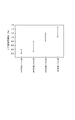
また、光ファイバプリフォームを線引きして光ファイバとする際には、例えば特開平6−171970号公報及び特開平9−243833号公報に提案される揺動線引き方法を採用した。この線引き方法は、線引き時に、回転軸が周期的に揺動するガイドローラで光ファイバをガイドすることにより、当該光ファイバに所定のねじりを付与する方法である。所定のねじりを光ファイバに付与することによりガラス軟化部が強制的にねじられ、その結果、光ファイバにおいて互いに直交する2つの偏波モードの間のモード結合が生じる。その際、偏波分散による入力パルスの広がりは、揺動を実施せず偏波モード間のモード結合が殆ど発生しない場合と比較して、1/(4Lh)1/2となる。ここで、Lは光ファイバ長(m)、hは光ファイバ長1m当たりの回転数(回/m)である。すなわち、hが大きいほど偏波モード分散は小さくなる。
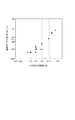
【0128】
図11は、光ファイバ母材のコア部非円率と光ファイバの偏波モード分散との関係を示すグラフである。同図から分かるように、光ファイバ母材のコア部非円率が1.5%以下の場合に、大容量伝送に好適な偏波モード分散値0.15ps/km1/2以下となることが分かる。また、光ファイバ母材のコア部非円率が0.5%以下の場合に、偏波モード分散値は0.05ps/km1/2以下となり更に好適であることが分かる。
【0129】
以上、幾つかの実施形態及び実施例を示して本発明に係る光ファイバ母材の製造方法について説明したが、本発明は上記実施形態に限られるものではなく様々な変形が可能である。
【0130】
第2の実施形態においては、ガラスパイプの一方の端部の近傍に2つの縮径部を設けるようにしたが、3つ以上の縮径部が設けられても良い。縮径部が3つ以上ある場合には、これらの縮径部のうちガラスパイプの一方の端部から最も遠い縮径部を除く何れかの縮径部において、ガラスロッドとガラスパイプとが互いに固定されるようにするとよい。
【0131】
さらに、上記実施形態及び実施例の幾つかにおいて有効部ガラスパイプの端部に高純度石英ガラスからなる補助ガラスパイプを接続したが、このような方法は、B2O3添加石英ガラスからなる有効部ガラスパイプを使用する場合に特に好適である。B2O3添加石英ガラスからなる有効部ガラスパイプに縮径部を形成し、この縮径部に有効部ガラスロッド又は有効部ガラスロッドに接続された補助ガラスロッドを溶融固定する際、有効部ガラスパイプの縮径部に大きな歪みが生じてしまう。そのため、有効部ガラスパイプの縮径部に多数のマイクロクラックが発生してしまう。その結果、有効部ガラスロッド又は有効部ガラスロッドに接続された補助ガラスロッドが縮径部から外れてしまうことがある。しかしながら、B2O3添加石英ガラスからなる有効部ガラスパイプに高純度石英ガラスからなる補助ガラスパイプを接続し、この補助ガラスパイプに縮径部を形成すれば、上記の問題を避けることができる。また、このとき用いる補助ガラスパイプは、高純度石英ガラス製に限らず、F又はClが添加された石英ガラス製であって良い。
【0132】
さらにまた、実施例8において、高純度ガラスからなるダミーパイプを有効部ガラスロッドの一方の端部に嵌め込むようにした。そして、補助ガラスパイプに形成される縮径部の内径は、有効部ガラスパイプに形成される縮径部の内径よりも、ダミーパイプの肉厚分だけ大きくした。これにより、有効部ガラスパイプ及び有効部ガラスロッドの中心軸をほぼ一致させるようにした。しかながら、ほぼ同一の外径を有するダミーパイプを有効部ガラスロッドの両端に1本ずつ接続し、縮径部の内径をすべてほぼ同一としてよい。
【0133】
【発明の効果】
以上説明したように、本発明に係る光ファイバ母材の製造方法によれば、ガラスパイプの両端部それぞれの近傍において縮径部が形成され、縮径部を有するガラスパイプにガラスロッドが挿入される。そして、縮径部のうち一方の縮径部において、ガラスロッドがガラスパイプに対して固定される。その後、熱源27を他方の縮径部から一方の縮径部へと向かう方向に移動させながらガラスパイプとガラスロッドとを加熱一体化することにより光ファイバ母材が製造される。したがって、偏波モード分散特性の良好な光ファイバの作製を可能とする非円率及び偏芯率が小さい光ファイバ母材が提供される。
【図面の簡単な説明】
【図1】図1は、実施形態の光ファイバ母材の製造方法に好適に使用される加熱装置の構成を示す概略図である。
【図2】図2(a)〜(g)は、第1の実施形態の製造方法の工程と、各工程終了時又は工程実施中の光ファイバ母材を示す模式図である。
【図3】図3(a)〜(f)は、第1の実施形態において、ガラスパイプに補助ガラスパイプを接続する例を示す模式図である。
【図4】図4(a)〜(h)は、第2の実施形態の製造方法の工程と、各工程終了時又は工程実施中の光ファイバ母材を示す模式図である。
【図5】図5(a)〜(e)は、第3の実施形態の製造方法の工程と、各工程終了時又は工程実施中の光ファイバ母材を示す模式図である。
【図6】図6(a)〜(f)は、第4の実施形態の製造方法の工程と、各工程終了時又は工程実施中の光ファイバ母材を示す模式図である。
【図7】図7は、補助ガラスパイプが接続された有効部ガラスロッドを示す図である。
【図8】図8は、コア部偏芯率の定義を説明する図である。
【図9】図9は、光ファイバ母材6A,6B,6S,6Tについて測定したコア部非円率を示すグラフである。
【図10】図10は、分散補償光ファイバの屈折率分布を示す概略図である。
【図11】図11は、光ファイバ母材のコア部非円率と光ファイバの偏波モード分散との関係を示すグラフである。
【符号の説明】
11…ガラスパイプ、11a,11b…縮径部、11c…固定縮径部、13…ダミーロッド、20…加熱装置、21a,21b…回転継手、22…ガス供給管、23…排気管、24…圧力ゲージ、25…熱源27、31a,31b…縮径部、31c…固定縮径部、33a,33b…補助ガラスロッド、41…挿入保護管、51a,51b,51c…縮径部、51d…固定縮径部、10,30,40,50,60…光ファイバ母材、61…有効部ガラスロッド、62…補助ガラスロッド、63…補助ガラスパイプ。[0001]
BACKGROUND OF THE INVENTION
The present invention is used for the production of an optical fiber. Optical fiber preform manufacturing method About.
[0002]
[Prior art]
The rod-in collapse method, in which a glass rod is inserted into a glass pipe and then heated to be integrated, is a base material or base material intermediate for an optical fiber having a complicated structure such as a dispersion compensating optical fiber or dispersion shifted fiber. It is widely used as a method suitable for the manufacture of
[0003]
[Problems to be solved by the invention]
In the above rod-in collapse method, when the glass rod is inserted into the glass pipe, it is necessary that the central axis of the glass rod and the central axis of the glass pipe coincide with each other with high accuracy. When they do not coincide with each other with accuracy, there arises a problem that the non-circularity or eccentricity of the core portion of the optical fiber preform obtained after the heat integration is increased. The same problem occurs when the glass rod is curved in the glass pipe. Furthermore, the center axis of the glass rod and the center axis of the glass pipe may be shifted during the heat integration, which causes a problem that the non-circularity or the eccentricity increases.
[0004]
If an optical fiber is produced from such an optical fiber preform having a large noncircularity or eccentricity, the noncircularity or eccentricity of the optical fiber itself is also deteriorated. Therefore, there has been a problem that the polarization mode dispersion characteristic of the optical fiber is deteriorated. If the polarization mode dispersion characteristic is not good, the signal light is likely to be deteriorated, and high-bit-rate optical transmission becomes difficult.
[0005]
The present invention has been made in view of such circumstances, and has a low non-circularity and eccentricity that enable the production of an optical fiber with good polarization mode dispersion characteristics. Optical fiber preform manufacturing method The purpose is to provide.
[0006]
[Means for Solving the Problems]
An optical fiber preform manufacturing method according to the present invention is a manufacturing method for manufacturing an optical fiber preform by inserting a glass rod into a glass pipe and heating and integrating the glass pipe and the glass rod with a heat source. The diameter of the pipe is reduced by heating, a reduced diameter portion forming step of providing a first reduced diameter portion and a second reduced diameter portion, and a glass rod is attached to the glass pipe having the first and second reduced diameter portions. In the inserting step, the fixing step of fixing the glass rod to the glass pipe by heating in the first reduced diameter portion, and the heat source in the direction from the second reduced diameter portion to the first reduced diameter portion. A heating integration step of heating and integrating the glass pipe and the glass rod while moving is sequentially performed.
[0007]
According to said manufacturing method, the glass rod inserted in the glass pipe is hold | maintained by the reduced diameter part provided in the vicinity part of the both ends of a glass pipe. Therefore, the glass rod can be held in a state where the central axes along the longitudinal direction of the glass rod and the glass pipe coincide with each other. Since the glass rod is held in this way, an optical fiber preform with low non-circularity and eccentricity can be obtained.
[0008]
Further, according to the knowledge of the present inventors, generally, when the glass rod and the glass pipe are integrated with heating, the glass rod moves so as to be drawn toward the heating part, that is, the melting part. When such movement occurs, the cross-sectional shape of the glass rod changes or the central axis thereof is shifted from the central axis of the glass rod. In the above manufacturing method, the glass rod is fixed to the glass pipe by heating at one reduced diameter portion, and the glass rod and the glass pipe are directed in a direction from the reduced diameter portion opposite to the fixed portion toward the fixed portion. Integration with heating is promoted. Therefore, it can prevent that a glass rod moves toward a fusion | melting part. Therefore, the increase in the non-circularity and the eccentricity due to the movement of the glass rod during melting can be suppressed. Therefore, an optical fiber preform having a sufficiently low non-circularity and eccentricity can be obtained.
[0009]
The optical fiber preform referred to here is a member used for manufacturing an optical fiber by drawing, or used to manufacture a so-called optical fiber preform by synthesizing a jacket portion on the outer peripheral surface thereof. Means an optical fiber preform intermediate or precursor.
[0010]
Further, in the method of manufacturing an optical fiber preform according to the present invention, the first auxiliary glass pipe is connected to one end of the effective portion glass pipe to be the clad portion, and the second auxiliary glass pipe is connected to the other end. A glass pipe manufacturing step of manufacturing a glass pipe by further performing before the reduced diameter portion forming step, and in the reduced diameter portion forming step, the first reduced diameter portion is formed on the first auxiliary glass pipe, and the second The reduced diameter portion may be formed in the second auxiliary glass pipe.
[0011]
According to said manufacturing method, a reduced diameter part is formed in the auxiliary glass pipe connected to each of the edge part of the effective part glass pipe. And a glass rod is inserted in the glass pipe which has a reduced diameter part in an auxiliary glass pipe. If the auxiliary glass pipe is connected so that its central axis coincides with the central axis of the glass pipe, the glass rod held by the reduced diameter portion in the glass pipe can also coincide with the central axis of the glass pipe. In this state, the glass rod is fixed to the glass pipe by heating at the first reduced diameter portion. Therefore, the glass rod and the glass pipe do not move when the central axes coincide with each other and when the heating is integrated. Therefore, an optical fiber preform having a low non-circularity and a low eccentricity can be produced.
[0012]
Furthermore, in the method of manufacturing an optical fiber preform according to the present invention, in the insertion step, the glass rod is inserted into the insertion protection tube, the insertion protection tube with the glass rod inserted is inserted into the glass pipe, and the glass The insertion protection tube inserted into the glass pipe may be extracted from the glass pipe while the rod remains in the glass pipe. Even in this manner, the glass rod inserted into the glass pipe can be held by the reduced diameter portion formed in the glass pipe so that the central axes of the glass pipe and the glass rod coincide. Further, the glass rod is fixed to the glass pipe by heating at one of the reduced diameter portions. Therefore, an optical fiber preform with a low non-circularity and a low eccentricity can be produced.
[0013]
Further, the use of the insertion protection tube can prevent the outer periphery of the glass rod and the inner periphery of the glass pipe from being damaged when the glass rod is inserted into the glass pipe. If the outer periphery of the glass rod and the inner periphery of the glass pipe are damaged, the following problems may occur. That is, there is a possibility that air bubbles may remain between the glass rod and the glass pipe during the heat integration due to the scratch itself or the glass particles generated by the scratch. When bubbles are generated in the optical fiber preform, the bubbles remain in the optical fiber manufactured from such an optical fiber preform, causing problems such as an increase in optical transmission loss and a decrease in the mechanical strength of the optical fiber. Occurs. However, if an insertion protection tube is used, scratches can be prevented, and such a problem can be prevented.
[0014]
Furthermore, in the method for manufacturing an optical fiber preform according to the present invention, it is between the first reduced diameter portion and the second reduced diameter portion, and is adjacent to the first reduced diameter portion. It is preferable that a third reduced diameter portion is further provided.
[0015]
When the glass rod and the glass pipe are fixed, for example, when a glass rod having a low softening point temperature is used, the glass rod may be bent at the fixing portion by heating. When such bending occurs, the glass rod is eccentric, and the eccentricity of the optical fiber preform is deteriorated. However, as described above, two reduced diameter portions are provided in the vicinity of one end of the glass pipe, and among these, the glass rod is fixed to the glass pipe at the reduced diameter portion near the open end of the glass pipe. For example, even if the glass rod is curved, the glass rod can be held by the reduced diameter portion adjacent to the fixed reduced diameter portion so that the central axis thereof coincides with the central axis of the glass pipe. Therefore, eccentricity is prevented at the portion where the glass rod is heated and integrated. As a result, a decrease in the eccentricity and non-circularity of the core portion of the optical fiber preform is reliably suppressed.
[0016]
Moreover, in the manufacturing method of the optical fiber preform of the present invention, in the first reduced diameter portion,
V ≧ {(r p / 2) 2 × π− (r r / 2) 2 × π)} × υ
However,
r p : Inner diameter (mm) of the portion excluding the reduced diameter portion of the glass pipe
r r : Outer diameter of the glass rod (mm)
υ: moving speed of the heat source (mm / min)
The flow rate V (mm Three / Min) is preferably provided between the glass pipe and the glass rod so that a gas can pass therethrough. In this way, when the glass pipe and the glass rod are integrated with heating, the gas between the glass pipe and the glass rod can flow out of the glass pipe, so the pressure inside the glass pipe increases during the heating integration. The glass pipe can be prevented from expanding. Note that r p And r r The volume of the gas determined by is the volume under the pressure of the gap between the glass pipe and the glass rod when the glass pipe and the glass rod are heated and integrated.
[0017]
In the first reduced diameter portion, each of the glass pipe and the glass rod is preferably either high-purity quartz glass or quartz glass to which fluorine, phosphorus, or chlorine is added. For example, GeO 2 When trying to melt and fix a glass rod made of quartz glass to which is added and a glass pipe, microcracks are generated in the glass rod, and the glass rod may come off from the glass pipe during heating integration. When the glass rod is detached from the glass pipe, the glass rod is eccentric with respect to the glass pipe. However, as described above, if the glass rod and the glass pipe in the first reduced diameter portion are high-purity quartz glass or quartz glass to which fluorine, phosphorus, or chlorine is added, both can be melted and fixed more reliably. . As a result, it is possible to reliably prevent the glass rod from being detached from the glass pipe during the heat integration. The high-purity quartz glass mentioned here means quartz glass to which impurities are not intentionally added in order to set the refractive index to a predetermined value, and its purity is 99.9 to 100 mol%. Means.
[0018]
In the first reduced diameter portion where the glass rod and the glass pipe are fixed, the glass rod and the glass pipe are either high-purity quartz glass or quartz glass to which fluorine, phosphorus, or chlorine is added. For this purpose, the following is preferable. That is, prior to the insertion step, a glass member connecting step of connecting a glass member made of either high purity quartz glass or quartz glass to which fluorine, phosphorus, or chlorine is added to at least one end of the glass rod is further performed. In the provision and fixing step, the glass member is preferably fixed to the first reduced diameter portion by heating. More preferably, the glass member is a third auxiliary glass pipe, and the glass rod and the third auxiliary glass pipe are connected by inserting the glass rod into the third auxiliary glass pipe.
[0019]
Further, when the inner diameter (diameter) of the first and second reduced diameter portions is D (mm) and the outer diameter (diameter) of the glass rod is d (mm), the relationship d <D ≦ d + 1 is satisfied. It is preferable. When the inner diameter D (mm) of the reduced diameter portion is equal to or smaller than the outer diameter d (mm) of the glass rod, the glass rod cannot be inserted into the glass pipe. Further, even when the inner diameter D (mm) of the reduced diameter portion is larger than the outer diameter d (mm) of the glass rod, the difference between the inner diameter D (mm) of the reduced diameter portion and the outer diameter d (mm) of the glass rod is different. If it is larger than 1 mm, the glass rod cannot be held so that the central axis of the glass rod and the central axis of the glass pipe coincide with each other. Therefore, the core part eccentricity of the optical fiber preform increases. If the inner diameter D (mm) of the reduced diameter portion is within the above range, an increase in the eccentricity of the core portion can be prevented.
[0020]
Furthermore, the inner diameter (diameter) of the glass pipe is set to D P (Mm) and when the outer diameter (diameter) of the glass rod is d (mm), 0.1 ≦ (D P It is preferable to satisfy the relationship −d) / 2 ≦ 3. (D P The value represented by -d) / 2 means a gap generated between the glass rod and the glass pipe when the glass rod is inserted into the glass pipe and the central axes of the both are made substantially coincide with each other. If this gap is smaller than 0.1 mm, air bubbles are easily formed between the glass pipe and the glass rod during the heat integration. On the other hand, if the gap is larger than 3 mm, it is difficult to uniformly shrink the glass pipe during the heat integration, and as a result, the non-circularity and the eccentricity increase. Air gap ((D P If -d) / 2) is in the above range, such problems can be prevented from occurring.
[0023]
DETAILED DESCRIPTION OF THE INVENTION
Hereinafter, preferred embodiments of an optical fiber preform and a method for manufacturing the same according to the present invention will be described with reference to the drawings. In the description of the drawings, the same elements are denoted by the same reference numerals, and redundant descriptions are omitted.
[0024]
First, a heating apparatus suitably used in the method for manufacturing an optical fiber preform according to the embodiment will be described. FIG. 1 is a schematic view showing a heating apparatus suitably used in the method for manufacturing an optical fiber preform according to the embodiment. The
[0025]
The
[0026]
(First embodiment)
1st Embodiment of the manufacturing method of the optical fiber preform which concerns on this invention is described. FIGS. 2A to 2G are schematic views showing the steps of the manufacturing method of the first embodiment and the optical fiber preform at the end of each step or during the steps.
[0027]
(Reduced diameter part process)
First, a
[0028]
After the
[0029]
The inner diameter of the
[0030]
After the etching is completed, the rotary joints 21 a and 21 b are removed, and the
[0031]
Here, the inner diameter of the reduced
[0032]
(Insertion process)
After forming the reduced
[0033]
(Fixing process)
After inserting the
[0034]
Here, in the fixed reduced
V ≧ {(r p / 2) 2 × π− (r r / 2) 2 × π)} × υ (1)
It is preferable to satisfy such a relationship. The right side of Equation (1) indicates how much the volume of the gap between the
[0035]
(Heating integration process)
After the fixed reduced
[0036]
As described above, in the method of manufacturing the optical fiber preform according to the first embodiment, the
[0037]
In the above description, the reduced diameter portion is formed in the vicinity of both ends of the
[0038]
Subsequently, the
[0039]
(Second Embodiment)
Next, a second embodiment of the optical fiber preform manufacturing method according to the present invention will be described. FIGS. 4A to 4H are schematic views showing the steps of the manufacturing method of the second embodiment and the optical fiber preform at the end of each step or during the steps.
[0040]
The second embodiment is almost the same as the first embodiment except that the method of inserting the glass rod into the glass pipe is different. In the following, differences will be mainly described.
[0041]
First, the reduced
[0042]
Then, the
[0043]
As described above, in the method of manufacturing the optical fiber preform according to the second embodiment, the
[0044]
Further, the use of the
[0045]
(Third embodiment)
A third embodiment of the optical fiber preform manufacturing method according to the present invention will be described. FIGS. 5A to 5E are schematic views showing the steps of the manufacturing method of the third embodiment and the optical fiber preform at the end of each step or during the steps.
[0046]
In the third embodiment, two reduced diameter portions are provided in the vicinity of one end portion of the
[0047]
As shown in FIG. 5A, two reduced
[0048]
Among the reduced
[0049]
As described above, in the third embodiment, the two reduced
[0050]
The method for manufacturing the optical fiber preform of the third embodiment is particularly effective when the
[0051]
(Fourth embodiment)
A fourth embodiment of the optical fiber preform manufacturing method according to the present invention will be described. FIGS. 6A to 6F are schematic views showing the steps of the manufacturing method of the fourth embodiment and the optical fiber preform at the end of each step or during the steps. The fourth embodiment is substantially the same as the first embodiment except that an auxiliary glass rod is connected to the glass rod. The differences will be mainly described below.
[0052]
First, as a raw material for manufacturing an optical fiber preform, GeO 2
[0053]
Subsequently, reduced
[0054]
As described above, in the method for manufacturing the optical fiber preform of the fourth embodiment, the
[0055]
Moreover, the manufacturing method of the optical fiber preform according to the fourth embodiment has the following effects.
[0056]
On the other hand, in the manufacturing method of the fourth embodiment, in the reduced
[0057]
In the above description, the
[0058]
The softening temperature of the effective
[0059]
When the
[0060]
Below, the manufacturing method of the optical fiber preform | base_material by this invention is demonstrated in detail using an Example.
[0061]
Example 1
In Example 1, (A) one auxiliary glass pipe is connected to each end of the glass pipe to be the cladding portion of the optical fiber preform, and (B) one diameter-reduced portion is provided to each of the two auxiliary glasses. (C) Insert a glass pipe to be the core of the optical fiber preform into the glass pipe, and (D) At one of the reduced diameter parts (fixed reduced diameter part), a glass rod is attached to the glass pipe. (E) An optical fiber preform was produced by heating and integrating the glass pipe and the glass rod while moving the
[0062]
Hereinafter, Example 1 will be described in detail. First, a glass pipe and a glass rod were prepared. This glass pipe is made of quartz glass to which 1.3 mol% of F is added, and has an inner diameter of 11 mm, an outer diameter of 30 mm, and a length of 450 mm. The glass rod is made of quartz glass added with 0.3 mol% of Cl and has an outer diameter of 8 mm and a length of 550 mm. Next, one auxiliary glass pipe was melted and connected to both ends of the glass pipe one by one using a heat source of the
[0063]
Subsequently, the glass pipe to which the auxiliary glass pipe was connected was rotated by the
[0064]
Next, the glass rod was inserted into a glass pipe having a reduced diameter portion. At this time, N ends from the end of the glass pipe opposite to the end into which the glass rod is inserted. 2 Gas was flown to prevent air from flowing into the glass pipe. The inserted glass rod was held in a reduced diameter portion provided in the glass pipe. Next, Cl into the glass pipe 2 Gas was supplied. N in the glass pipe 2 Gas is Cl 2 After being replaced with gas, the glass pipe and the glass rod were rotated. Subsequently, one of the reduced diameter portions was heated from the outside of the auxiliary glass pipe using the
[0065]
Thus, the optical fiber preform of Example 1 was obtained. This optical fiber preform is referred to as an optical fiber preform 1A for convenience of explanation. Subsequently, at a plurality of measurement points along the longitudinal direction of the optical fiber preform 1A, the core non-circularity and the core eccentricity were measured using a preform analyzer or the like. As a result, at any measurement point, the core non-circularity was 0.1 to 0.4% and the core eccentricity was 0.1 to 0.5%.
[0066]
Here, the core part non-circularity is obtained by approximating the cross-sectional shape in the radial direction of the core part to an ellipse, and the major axis 2a of the obtained ellipse. max And minor axis 2a min And (2a max -2a min ) / 2a max It is defined by x100 (%). The core eccentricity is the maximum value d of the distance between the center of the core part and the outer periphery of the cladding part in the cross section of the optical fiber preform as shown in FIG. max And the minimum value d min (D max -D min ) / (D max + D min ) × 100 (%).
[0067]
Further, for comparison with Example 1, as Comparative Example 1S, the above steps (A), (B), and (C) were sequentially performed, and then the glass rod and the glass pipe were not subjected to the procedure (D). Were integrated by heating to prepare an optical fiber preform. The glass rod, glass pipe, auxiliary glass pipe, and heating conditions used for the production were substantially the same as in Example 1. The optical fiber preform manufactured in Comparative Example 1S is referred to as an optical fiber preform 1S. At a plurality of measurement points along the longitudinal direction of the optical fiber preform 1S, the core non-circularity and the core eccentricity were measured using a preform analyzer. As a result, at any measurement point, the core part non-circularity was 1.5 to 2.5%, and the core eccentricity was 3 to 10%.
[0068]
Further, in order to compare with the optical fiber preforms 1A and 1S, as the comparative example 1T, the above steps (A) and (C) are sequentially performed, and then the glass pipe and the glass rod are heated and integrated to form an optical fiber preform. Was made. The glass rod, glass pipe, auxiliary glass pipe, and heating conditions used for the production were substantially the same as in Example 1. The optical fiber preform manufactured in Comparative Example 1T is referred to as an optical fiber preform 1T. When the core non-circularity and the core eccentricity were measured for the optical fiber preform 1T, the core non-circularity was a value of 1.8 to 4.2% at a plurality of measurement points along the longitudinal direction. The core eccentricity was 17 to 20%. Comparing the optical fiber preforms 1A, 1S, and 1T, it can be seen that the optical fiber preform 1A is superior to the optical fiber preforms 1S and 1T in terms of the core non-circularity and the core eccentricity.
[0069]
(Example 2)
Example 2 corresponds to the second embodiment described above. That is, in Example 2, the glass rod is inserted into the glass rod after being inserted into the insertion protection tube made of Teflon. Thereafter, when only the insertion protection tube is pulled out, the glass rod is held in the reduced diameter portion of the glass pipe. The detailed procedure will be described below.
[0070]
First, a glass pipe and a lath rod were prepared. This glass pipe is made of quartz glass to which 1.3 mol% of F is added, and has an inner diameter of 9 mm, an outer diameter of 30 mm, and a length of 400 mm. The glass rod is made of quartz glass to which 0.3 mol% of chlorine is added, and has an outer diameter of 8 mm and a length of 450 mm. Next, a glass pipe was attached to the heating device. Continue to rotate the glass pipe, SF in the glass pipe 6 Gas was supplied. The glass pipe was heated to a temperature of about 1500 ° C. by the
[0071]
Next, the glass rod was inserted into an insertion protection tube made of Teflon. The insertion protective tube has an inner diameter of 8.1 mm and an outer diameter of 8.4 mm. Thereafter, the insertion protective tube into which the glass rod was inserted was inserted into a glass pipe having a reduced diameter portion. After inserting the insertion protection tube into the glass pipe, only the insertion protection tube was pulled out. After the insertion protection tube was pulled out, the glass rod was held by a reduced diameter portion provided in the glass pipe.
[0072]
Then Cl 2 While flowing the gas, the glass pipe and the glass rod are rotated, and one of the reduced diameter portions is heated from the outside of the glass pipe using the
[0073]
Thus, an optical fiber preform was obtained. For convenience of explanation, this optical fiber preform is referred to as an optical fiber preform 2A. As a result of measurement using a preform analyzer or the like, it was found that the outer diameter (diameter) of the optical fiber preform 2A was about 29 mm, and the outer diameter of the core portion was about 8 mm. In addition, no bubbles were observed inside the optical fiber preform 2A. Subsequently, quartz glass to which 1.3 mol% of F was added was jacketed on the outer peripheral surface of the optical fiber preform 2A. In this way, an optical fiber preform 20A having a cladding diameter / core diameter ratio of 12.7 was obtained. Thereafter, the optical fiber preform 20A was drawn to produce an optical fiber having an outer diameter of 125 μm. When the transmission loss of this optical fiber was measured, a value of 0.165 dB / km was obtained at a wavelength of 1550 nm.
[0074]
For comparison, as Comparative Example 2S, an attempt was made to use an insertion protection tube made of quartz glass instead of the above-mentioned insertion protection tube made of Teflon. The quartz glass insertion protective tube used had an inner diameter of 8.1 mm and an outer diameter of 8.4 mm. An optical fiber preform 2S was produced by the same procedure as in Example 2 except that the material of the insertion protection tube was different. When the number of bubbles inside the optical fiber preform 2S was measured, it was about 2 on average at 300 mm. Subsequently, an optical fiber preform 20S having a cladding diameter / core diameter ratio of 12.7 was produced by jacketing the outer periphery of the optical fiber preform 2S in the same manner as the optical fiber preform 20A. Thereafter, the optical fiber preform 20S was drawn to produce an optical fiber having an outer diameter of 125 μm in the cladding region. As a result of measuring the transmission loss of this optical fiber, a value of 0.165 dB / km was obtained at a wavelength of 1550 nm.
[0075]
For further comparison, as a comparative example 2T, an optical fiber preform 2T was manufactured by the same procedure as in the example 2 except that no insertion protection tube was used. When the number of bubbles inside the optical fiber preform 2T was measured, it was about 6 on average per 300 mm. Subsequently, the outer periphery of the optical fiber preform 2T was jacketed to produce an optical fiber preform 20T. The optical fiber preform 20T was drawn to produce an optical fiber so that the outer diameter of the cladding region was 125 μm. As a result of measuring the transmission loss of this optical fiber, a value of 0.175 dB / km was obtained at a wavelength of 1550 nm.
[0076]
As described above, a transmission loss that is sufficiently low in practice can be obtained even when the insertion protection tube is not used, but the transmission loss can be further reduced by using the insertion protection tube. This is presumably because the use of the insertion protective tube makes it difficult for the glass rod or the glass pipe to be damaged, and there is no generation of glass particles or the like. That is, if there are scratches, glass particles, etc., these become nuclei and bubbles are likely to be generated. However, the use of an insertion protective tube can suppress the generation of scratches, glass particles, etc., so that the number of bubbles can be reduced. When bubbles are generated in the optical fiber preform, the mechanical strength of the optical fiber manufactured from the optical fiber preform is significantly reduced. According to the present embodiment, since the generation of bubbles can be reduced, it is possible to prevent the mechanical strength of the manufactured optical fiber from being lowered.
[0077]
Example 3
Example 3 corresponds to the first embodiment. For comparison, optical fiber preforms were manufactured under the conditions that did not satisfy the formula (1) as Comparative Examples 3S to 3U.
[0078]
In preparing the optical fiber preform of Example 3, first, a glass pipe and a glass rod were prepared. The glass pipe is made of quartz glass to which 1.3 mol% of F is added, and has an inner diameter (diameter) of about 6 mm, an outer diameter (diameter) of about 35 mm, and a length of about 300 mm. The glass rod is made of high purity quartz glass and has an outer diameter (diameter) of about 4 mm and a length of about 350 mm.
[0079]
One reduced diameter portion having an inner diameter (diameter) of 4.3 mm was formed near both ends of the glass pipe. This procedure was almost the same as the procedure for forming the reduced diameter portion in Example 1. After forming the reduced diameter portion, the glass rod was inserted into the glass pipe. The glass rod was fixed to the glass pipe by heating one of the reduced diameter portions (fixed reduced diameter portion). At this time, the gas existing between the glass pipe and the glass rod is 480 mm under the condition of heating integration described later. Three A gap that allows passage at a flow rate of about / min was provided in the fixed reduced diameter portion.
[0080]
Subsequently, the glass pipe and the glass rod were integrated by heating in substantially the same procedure as in Example 1 to manufacture an optical fiber preform 3A. However, Cl supplied into the glass pipe 2 The gas flow rate is 2.0 × 10 Five mm Three / Min. Further, during the heat integration, the pressure in the glass pipe was adjusted to be −4 kPa as indicated by the
[0081]
As Comparative Example 3S, when the glass rod was fixed to the glass pipe, a gap having a predetermined size was provided in the fixed reduced diameter portion. This gap is obtained when the glass pipe and the glass rod are heated and integrated under the same heating and integration conditions as in Example 3, and the gas existing between the glass pipe and the glass rod is 405 mm. Three The size is such that it can pass at a flow rate of about / min. Although the optical fiber preform 3S was produced in this manner, a part of the glass pipe expanded during the heat integration, and relatively large bubbles were generated in the optical fiber preform 3S.
[0082]
In Comparative Example 3T, gaps of different sizes were provided in the fixed reduced diameter portion. When this gap is heated and integrated under the same conditions as in Example 3, the gas present between the glass pipe and the glass rod is 197 mm. Three The size is such that it can pass at a flow rate of about / min. In Comparative Example 3U, 109 mm Three A gap that allows passage at a flow rate of about / min was provided in the fixed reduced diameter portion. In Comparative Examples 3T and 3U, the glass pipe expanded during heating integration. As a result, the heating integration cannot be continued, and the production of the optical fiber preform has to be stopped.
[0083]
As described above, the inner diameter (diameter) of the portion other than the reduced diameter portion of the glass pipe used in Example 3 and Comparative Examples 3S to 3U is about 6 mm, and the outer diameter (diameter) of the glass rod is about 4 mm. . 471mm when calculating the right side of Formula (1) from these values. Three A flow rate value of / min is obtained. That is, in Example 3 and Comparative Examples 3S to 3U, only the optical fiber preform 3A of Example 3 was manufactured to satisfy the formula (1). From the results obtained in Example 3 and Comparative Examples 3S to 3U, it can be seen that a good optical fiber preform can be obtained when manufactured under conditions that satisfy the above-described formula (1).
[0084]
Example 4
In Example 4, two auxiliary glass pipes connected to each of both ends of a glass pipe (hereinafter referred to as an effective portion glass pipe) to be a clad portion of the optical fiber preform are provided on one auxiliary glass. An optical fiber preform was produced by substantially the same procedure as in Example 1 except that the reduced diameter portion was formed. The fourth embodiment will be described below with a focus on the differences.
[0085]
First, an effective portion glass pipe, a glass rod, and two auxiliary glass pipes were prepared. The effective portion glass pipe is made of quartz glass added with 0.2 mol% of Cl, and has an outer diameter of 25 mm. The glass rod is made of quartz glass added with 1.5 mol% of F and has an outer diameter of 3 mm. The auxiliary glass pipe is made of high-purity quartz glass, and has an outer diameter and an inner diameter substantially equal to those of the effective portion glass pipe. Next, one auxiliary glass pipe was melted and connected to both ends of the effective part glass pipe. In this connection, the central axes of the effective portion glass pipe and the auxiliary glass pipe were made to coincide with each other.
[0086]
Subsequently, the effective part glass pipe to which the auxiliary glass pipe was connected was attached to the
[0087]
Cl in the effective part glass pipe to which the auxiliary glass pipe is connected 2 Gas was flowed and the glass rod was melted and fixed to the auxiliary glass pipe. Here, the fixed reduced diameter portion in which the glass rod is fixed to the auxiliary glass pipe is a reduced diameter portion close to the open end of the auxiliary glass pipe in which two reduced diameter portions are formed. Moreover, the surface temperature of the glass pipe was 1550 degreeC at the time of fixation. When the fixed reduced diameter portion was observed, the glass rod was curved in the fixed reduced diameter portion. This is because (1) the outer diameter of the glass rod is relatively thin, 3 mm as described above, and (2) because F is added to the glass rod, the softening temperature is lower than that of the glass pipe. The present inventors are thinking. However, the curved portion is limited between the fixed reduced diameter portion and the adjacent reduced diameter portion, and particularly between the adjacent reduced diameter portion and the reduced diameter portion on the opposite side of the glass pipe, particularly the effective portion. No curvature of the glass rod was observed in the portion inside the glass pipe, and the central axes of the effective portion pipe and the glass rod almost coincided.
[0088]
Subsequently, the optical fiber preform 4 was obtained by heating and integrating the glass pipe and the glass rod by substantially the same procedure as in Example 1. However, here, Cl 2 The gas flow rate is 3.0 × 10 Five mm Three / Min, and the pressure in the glass pipe during heating integration was -1.5 kPa (indicated value of pressure gauge). The outer diameter of the optical fiber preform 4 was 23.9 mm. Next, the non-circularity of the core portion was measured at several measurement points along the longitudinal direction of the optical fiber preform 4. As a result, it was confirmed that the core non-circularity of the optical fiber preform 4 was a good value of 0.1 to 0.2%.
[0089]
For comparison, an optical fiber preform 4S was manufactured by providing one reduced diameter portion for each auxiliary glass pipe and other procedures and conditions being the same as those in Example 4. The core part non-circularity of the optical fiber preform 4S was 1.5 to 2.2%. From the above results, the effect of Example 4 is understood.
[0090]
(Example 5)
In Example 5, a glass pipe made of quartz glass added with 0.2 mol% of Cl, having an inner diameter of 6 mm and an outer diameter of 25 mm (hereinafter referred to as an effective portion glass pipe), GeO, and 2 A glass rod (hereinafter referred to as an effective portion glass rod) having an outer diameter of 3 mm was used.
[0091]
Further, depending on whether or not the auxiliary glass pipe is connected to the end of the effective part glass pipe and whether or not the auxiliary glass rod is connected to the end of the effective part glass rod, the following combinations of glass pipe and glass rod are used. An optical fiber preform was prepared.
(A) Example 5A: Effective portion glass pipe to which an auxiliary glass pipe made of high purity quartz glass is connected, and an effective portion glass rod to which an auxiliary glass rod made of high purity quartz glass is connected.
(B) Example 5B: Effective portion glass rod to which an auxiliary glass pipe made of high-purity quartz glass is connected and an auxiliary glass rod made of quartz glass to which 1 mol% of F is added are connected.
(C) Example 5C: An effective portion glass rod in which an effective portion glass pipe without connection of an auxiliary glass pipe and an auxiliary glass rod made of high-purity quartz glass are connected.
[0092]
In Examples 5A to 5C, when the auxiliary glass pipe was connected to the effective portion glass pipe, a reduced diameter portion was formed in the auxiliary glass pipe. Similarly to Example 4, two reduced diameter portions were provided in the vicinity of one end of the effective glass pipe when one of the auxiliary glass pipes was not used or when the auxiliary glass pipe was not used. The glass rod and the glass pipe were melted and fixed at a reduced diameter portion closer to the open end portion of the two reduced diameter portions. The temperature of the auxiliary glass pipe surface during fixing was 1400 ° C. in Example 5A and 1350 ° C. in Examples 5B and 5C. The heating integration procedure and conditions were substantially the same as in Example 1 described above, and an optical fiber preform 5A in Example 5A, an optical fiber preform 5B in Example 5B, and an optical fiber preform 5C were manufactured. .
[0093]
When the core portion non-circularity was measured for the optical fiber preforms 5A to 5C, it was 0.2 to 0.6% for the optical fiber preform 5A, and 0.1 to 0.00 for both of the optical fiber preforms 5B and 5C. 3%. From these results, it can be seen that an optical fiber preform having a good core non-circularity was obtained in any case. In particular, the optical fiber preforms 5B and 5C have a lower core non-circularity than the optical fiber preform 5A. The present inventors presume that this result is caused by a difference in melting point of quartz glass at the fixed reduced diameter portion. That is, as described above, in the optical fiber preform 5A, the glass rod and the glass pipe are made of high-purity quartz glass at the fixed reduced diameter portion. On the other hand, the optical fiber preform 5B is made of high-purity quartz glass (auxiliary glass pipe) and F-added quartz glass (auxiliary glass rod). Further, in the optical fiber preform 5C, a Cl-added glass pipe (effective portion glass rod) and a high-purity glass rod (auxiliary glass rod) are used. That is, in the case of the optical fiber preforms 5B and 5C, the heating temperature at the time of melting and fixing the glass rod to the glass pipe can be lowered as compared with the case of the optical fiber preform 5A. It is considered that the glass rod is less likely to be deformed as the melting temperature is lower. Therefore, it can be considered that the core part non-circularity of the optical fiber preform is lowered.
[0094]
For comparison with Examples 5A to 5C, a glass pipe in which an auxiliary glass pipe made of high-purity quartz glass is connected to the end of the effective part glass pipe, and the effective part glass rod (GeO). 2 Was used, and an optical fiber preform 5S was tried under substantially the same manufacturing procedure and conditions as in Example 5A. However, a situation in which the effective portion glass rod comes off from the fixed reduced diameter portion during the heat integration occurred. Although the same production was attempted three times, the effective portion glass rod was detached from the fixed reduced diameter portion in all three times. Even when it came off, the heating integration was continued and the optical fiber preform 5S was manufactured. When the core non-circularity of the optical fiber preform 5S was measured, a value of 2.0 to 3.2% was obtained.
[0095]
During the heating integration, since the glass rod and the glass pipe are melted in the heating part, a force that is drawn toward the melting part acts on the glass rod. Therefore, if a glass rod will remove | deviate from a fixed diameter reduction part, it will move toward a fusion | melting part. When such movement occurs, the eccentricity of the glass rod occurs, and as a result, the core part non-circularity increases. Further, as a cause of the effective portion glass rod coming off the fixed reduced diameter portion, the present inventors have made GeO 2 In the case of the effective portion glass rod made of the added silica glass, it is considered that a large strain is generated in the fixed reduced diameter portion, and a large number of microcracks are generated by this strain. It can be considered that the glass rod has been detached from the glass pipe due to the occurrence of microcracks.
[0096]
(Example 6)
In Example 6, a glass pipe made of quartz glass to which Cl is added at 0.2 mol%, having an inner diameter of 7 mm and an outer diameter of 30 mm (hereinafter referred to as an effective part glass pipe), GeO 2 A glass rod (hereinafter referred to as an effective portion glass rod) having an outer diameter of 4 mm was used. Two of these were prepared. Further, an auxiliary glass pipe made of high-purity quartz glass having substantially the same inner diameter, outer diameter, and wall thickness as the effective portion glass pipe was connected to both ends of each of the two effective portion glass pipes. Two reduced diameter portions were formed on one side of the auxiliary glass pipe, and one reduced diameter portion was formed on the other side. The inner diameter of the reduced diameter portion was 4.5 mm on one of the two glass pipes and 5.0 mm on the other.
[0097]
Subsequently, an optical fiber preform was manufactured by substantially the same procedure as that in Example 4. Specifically, the main conditions at the time of heating integration are Cl 2 Gas supply amount 3.0 × 10 Five mm Three / Min, O 2 Gas supply amount 3.0 × 10 Five mm Three / Min, the moving speed of the
[0098]
For comparison, two sets of glass pipes, glass rods, and auxiliary glass pipes, which are substantially the same as those used for the production of the optical fiber preforms 6A and 6B, were prepared. One auxiliary glass pipe was formed at each end of the effective portion glass pipe. Then, the diameter reduction part was provided in the auxiliary glass pipe similarly to the time of manufacture of optical fiber preform 6A and 6B. However, the inner diameter was 5.5 mm for one glass pipe and 6.0 mm for the other. Thereafter, optical fiber preforms 6S and 6T were produced by the same production procedure and conditions as those for producing optical fiber preforms 6A and 6B.
[0099]
FIG. 9 is a graph showing the core non-circularity measured for the manufactured optical fiber preforms 6A, 6B, 6S, and 6T. As can be seen from the figure, values of 0.2 to 0.4% are obtained for the optical fiber preform 6A, and 0.3 to 0.8% are obtained for the optical fiber preform 6B. Further, the non-circularity of the core part of the optical fiber preform 6S manufactured with the inner diameter of the reduced diameter part being 5.5 mm is 0.8 to 1.2%, and a relatively good value of 0.8% is obtained. However, the core non-circularity tended to be slightly higher. Further, in the optical fiber preform 6S manufactured with the inner diameter of the reduced diameter portion of 6.0 mm, the core portion non-circularity was a relatively high value of 1.0 to 1.5%.
[0100]
From the above results, it is understood that particularly good non-circularity can be obtained when the inner diameter of the reduced diameter portion is 4.5 mm (optical fiber preform 6A) and 5.0 mm (same 6B). That is, it is particularly preferable that the difference between the inner diameter of the reduced diameter portion and the outer diameter of the glass rod is 1 mm or less. Further, when this difference is larger than 1 mm, the glass rod and the central axis of the glass pipe are difficult to coincide with each other when the glass rod is inserted into the glass pipe. The present inventors believe that this tendency appears. Moreover, it cannot be overemphasized that a glass rod cannot be inserted in a glass pipe as the internal diameter of a diameter reduction part is below the outer diameter of a glass rod.
[0101]
(Example 7)
In Example 7, five glass pipes (hereinafter, effective portion glass pipes) made of quartz glass with 1.1 mol% of F added and having an outer diameter of 25 mm were prepared as glass pipes. Here, the inner diameters of the five effective portion glass pipes are different in the range of 6.3 to 11.7 mm as shown in the column of “inner diameter” in Table 1 below. In addition, as a glass rod used in combination with these effective portion glass pipes, GeO 2 5 glass rods (hereinafter, effective portion glass rods) having an outer diameter of 6.1 mm were prepared.
[0102]
An auxiliary glass pipe made of high purity quartz glass, having an inner diameter of 8 mm and an outer diameter of 25 mm was connected to both ends of the effective portion glass pipe. At the time of this connection, the central axes of the auxiliary glass pipe and the effective part glass pipe were substantially matched. Two reduced diameter portions were formed on one side of the auxiliary glass pipe, and one reduced diameter portion was formed on the other side. After forming the reduced diameter portion, the effective portion glass pipe was inserted into the effective portion glass pipe to which the auxiliary glass pipe was connected. Then, in the heating apparatus shown in FIG. 1, the effective part glass pipe to which the auxiliary glass pipe was connected was attached to the heating apparatus by connecting the rotary joint to both of the auxiliary glass pipes. In the auxiliary glass pipe formed with two reduced diameter portions, the effective portion glass rod and the auxiliary glass pipe were melted and fixed at the reduced diameter portion close to the open end of the auxiliary glass pipe among the two reduced diameter portions. After fixing the effective part glass rod and the auxiliary glass pipe, the effective part glass rod and the glass pipe were heated and integrated. The condition for heat integration is Cl 2 Gas supply amount is 3.0 × 10 Five mm Three / Min and O 2 Gas supply amount is 3.0 × 10 Five mm Three / Min, and the moving speed of the
[0103]
In the following description, as shown in Table 1, optical fiber preforms manufactured using effective portion glass pipes having different inner diameters are denoted as optical fiber preforms 7A to 7E. Visual inspection and core portion non-circularity measurement were performed on the optical fiber preforms 7A to 7E. In the appearance inspection, the number of bubbles existing inside the optical fiber preforms 7A to 7E was counted. Table 1 shows the measured values of the core portion non-circularity of the optical fiber preforms 7A to 7E. In the table, “void” means the inner diameter of the glass pipe as D P When (mm) and the diameter of the glass rod is d (mm), (D P A value represented by -d) / 2.
[0104]
As can be seen from Table 1, although the optical fiber preform 7A has a slightly higher core non-circularity than the optical fiber preforms 7B to 7E, good results were obtained. Further, no bubbles were observed in the optical fiber preforms 7A to 7D. In the optical fiber preform 7E, an average of about 1 bubble was recognized at 50 mm, but the core non-circularity was very good at 0.1 to 0.2%. Must not.
[Table 1]
For comparison with the optical fiber preforms 7A to 7E, an optical fiber preform was manufactured as follows. First, the effective part glass pipe used for manufacturing the optical fiber preforms 7A to 7E and three effective part glass pipes having the same outer diameter and the same F concentration and different inner diameters are prepared, and the optical fiber preforms 7A to 7E are prepared. Three glass rods substantially the same as the effective portion glass rods used in the manufacture of 7E were prepared. The inner diameters of the three effective portion glass pipes are 13.9 mm, 13.1 mm, and 6.2 mm, respectively. For convenience, the optical fiber preform manufactured using the effective portion glass pipe having the inner diameter of 13.9 mm is the optical fiber preform 7S, the optical fiber preform manufactured using the effective portion glass pipe having the inner diameter of 13.1 mm is the optical fiber preform 7T, and An optical fiber preform 7U is manufactured using an effective portion glass pipe having an inner diameter of 6.2 mm. The optical fiber preforms 7S to 7U were manufactured with substantially the same manufacturing procedure and conditions as those of the optical fiber preforms 7A to 7E.
[0106]
Visual inspection and core part non-circularity measurement were performed on the optical fiber preforms 7S to 7U. Table 2 shows the result of the core non-circularity. In the optical fiber preform 7U, many bubbles are generated over the entire preform, and the core non-circularity cannot be measured. Although no bubbles were observed in the optical fiber preform 7S, the core non-circularity was 1.2 to 1.6%, which was not a preferable result. Furthermore, in the optical fiber preform 7T, no bubbles were observed, and the core non-circularity was as good as 0.8%, but the overall result was not very good.
[0107]
From the above results, the “gap” between the effective portion glass rod and the effective portion glass pipe ((D P It is understood that a particularly good core non-circularity can be obtained when -d) / 2) is 0.1 mm or more and 3.0 mm or less.
[Table 2]
(Example 8)
As Example 8, an optical fiber preform suitable for manufacturing a dispersion compensating optical fiber and an optical fiber manufactured by drawing the optical fiber preform were manufactured. FIG. 10 is a schematic diagram showing the refractive index distribution of the dispersion compensating optical fiber. As illustrated, the dispersion compensating optical fiber has a depressed refractive index profile. That is, this optical fiber has a core region, a first cladding region, and a second cladding region. Here, the relative refractive index difference Δ of the core region with respect to the second cladding region is 1.50%, and the relative refractive index difference Δ of the first cladding region with respect to the second cladding region is −0.45%. The outer diameter of the core region is 4.0 μm, and the outer diameter of the first cladding region is 7.9 μm. An optical fiber preform for manufacturing such an optical fiber includes a core portion corresponding to the core region, a first cladding portion corresponding to the first cladding region, and a second cladding portion corresponding to the second cladding region. Have.
[0109]
First, a quartz glass pipe (hereinafter referred to as an effective portion glass pipe) containing 1.4 mol% F, having an inner diameter of 6 mm and an outer diameter of 25 mm, and GeO 2 And a quartz glass rod (hereinafter, effective portion glass rod) having an outer diameter of 6.1 mm. A core portion is formed from the effective portion glass rod, and a first cladding portion is formed from the effective portion glass pipe. GeO of effective part glass rod 2 The density n is the maximum value n 0 Is 15 mol%, where r (r ≦ a) is the distance from the central axis, and a radius of the effective part glass rod is a, n (r) = n 0 × {1- (r / a) 2.0 } To be approximated by an expression such as These effective portion glass pipes and effective portion glass rods are produced by the VAD method.
[0110]
A dummy pipe made of high-purity quartz glass and having an outer diameter of 6.3 mm and an inner diameter of 6.11 mm was fitted into one end of the effective portion glass rod. Subsequently, the effective part glass rod fitted with the dummy pipe was immersed in a hydrofluoric acid (HF) solution, and etching was performed until the outer diameter of the effective part glass rod became 6.0 mm and the outer diameter of the dummy pipe became 6.2 mm. . Thereby, the dust etc. adhering to the outer peripheral surface of the effective part glass rod were also removed.
[0111]
Subsequently, an auxiliary glass pipe made of high-purity quartz glass and having an outer diameter of 25 mm and an inner diameter of 6.5 mm was connected to one end of the effective part glass pipe. Subsequently, the effective part glass pipe to which the auxiliary glass pipe was connected was attached to the
[0112]
The above-mentioned effective portion glass rod was inserted into an insertion protective tube made of Teflon, having an outer diameter of 6.4 mm and an inner diameter of 6.2 mm. The insertion protection tube in which the effective portion glass rod was inserted was inserted into the glass pipe provided with the reduced diameter portion, and then only the insertion protection tube was pulled out. At this time, of the two reduced diameter portions provided in the auxiliary glass pipe, the reduced diameter portion close to the open end of the auxiliary glass pipe has a dummy pipe fitted into the effective portion glass rod, and the adjacent reduced diameter portion. There was an effective part glass rod in the diameter part. Moreover, there was an effective portion glass rod in one reduced diameter portion provided in the effective portion glass pipe.
[0113]
The dummy pipe and the auxiliary glass pipe were melt-fixed at the reduced diameter portion close to the open end of the auxiliary glass pipe among the two reduced diameter portions provided in the auxiliary glass pipe. At this time, it fixed so that a clearance gap might remain between a dummy pipe and an auxiliary glass pipe. Furthermore, the gas existing between the effective portion glass pipe and the effective portion glass rod through the gap is 1000 mm. Three Passing at a flow rate of / min was confirmed.
[0114]
Next, Cl is supplied from the
[0115]
The outer diameter of the first glass body was 24 mm. From the appearance inspection, it was found that no bubbles were generated in the first glass body. Moreover, as a result of measuring the core part non-circularity of the 1st glass body, the favorable value of 0.1% or less was obtained over the full length of the 1st glass body.
[0116]
The first glass body was structurally examined using a preform analyzer or the like, and then stretched by the
[0117]
The second glass body was etched with an HF solution to make the outer diameter 5.5 mm. Since the auxiliary glass rod of the second glass body and the outer layer portion of the first glass body have the same F addition concentration, the etching rate is substantially the same in the entire outer peripheral portion of the second glass body. Therefore, the outer diameter of the second glass body was substantially the same (5.5 mm) along the longitudinal direction including the auxiliary glass rod. Moreover, as a result of etching, the diameter ratio of the effective portion glass rod to be the core portion and the region to be the first cladding portion was 2.04 times. Furthermore, as a result of the etching, impurities such as OH groups adhering and penetrating into the surface layer portion during the heat integration and stretching were removed by etching, and the surface layer portion of the second glass body after the etching was cleaned.
[0118]
Then, the 2nd effective part glass pipe which should become a 2nd clad part was prepared. The second effective portion glass pipe is made of quartz glass containing 0.2 mol% of Cl, and has an outer diameter of 30 mm and an inner diameter of 5.5 mm. The second effective portion glass pipe is manufactured from the VAD method.
[0119]
A second auxiliary glass pipe made of high-purity quartz glass and having an outer diameter of 30 mm and an inner diameter of 6.0 mm was connected to one end of the second effective part glass pipe. Thereafter, the second effective glass pipe (hereinafter referred to as the second glass pipe) to which the second auxiliary glass pipe is connected is heated, and SF 6 To etch the inner surface of the second glass pipe. The inner diameter of the second glass pipe was set to 7.0 mm by etching. Thereafter, two reduced diameter portions were formed in the second auxiliary glass pipe, and one reduced diameter portion was formed in the vicinity of the open end portion of the second effective portion glass pipe. The inner diameters of these reduced diameter portions were all 6.0 mm.
[0120]
Next, an insertion protective tube made of Teflon having an outer diameter of 5.9 mm and an inner diameter of 5.6 mm was prepared. And the 2nd glass body which performed the etching previously was inserted in the inside of this insertion protection tube. Then, the insertion protection tube which has a 2nd glass body inside was inserted in said 2nd glass pipe. After insertion, only the insertion protection tube was pulled out. At this time, of the two reduced diameter portions formed in the second auxiliary glass pipe, the auxiliary glass rod of the second glass body is supported by the reduced diameter portion close to the open end of the second auxiliary glass pipe. The first glass body is supported by the adjacent reduced diameter portion. The first glass body is supported by the reduced diameter portion formed in the second effective portion glass pipe. And the 2nd glass body and the 2nd glass pipe were mutually fixed by melt-heating the diameter-reduced part near an open end part and an auxiliary glass rod among two diameter-reduced parts. When fixing, a gap was formed in the fixing part. Also, through this gap, 1000mm Three / Min gas was confirmed to flow.
[0121]
Subsequently, Cl from the gas supply pipe of the heating device 2 5.0 x 10 gas Five mm Three / Min was supplied, and the second glass pipe and the second glass body were heated to 1100 ° C. using the
[0122]
The outer diameter of the optical fiber preform was 29 mm. Further, when the optical fiber preform intermediate was inspected for appearance, no generation of bubbles was observed. In addition, the core non-circularity of the optical fiber preform was 0.3% or less over the entire length, which was a favorable result.
[0123]
After performing a structural inspection on the optical fiber preform intermediate using a preform analyzer, a jacket portion containing 0.2 mol% of Cl is synthesized on the outer periphery of the optical fiber preform intermediate, and an optical fiber preform is prepared. Produced. Since the Cl content of the jacket portion is substantially equal to that of the second effective portion glass pipe, the thickness of the second cladding portion is substantially increased by the synthesis of the jacket portion. The diameter ratio of the first cladding portion and the second cladding portion of the optical fiber preform was 15.8.
[0124]
The optical fiber preform obtained as described above was drawn by a predetermined drawing method to produce an optical fiber having an outer diameter of 125 μm. When the transmission characteristics of the obtained optical fiber were measured, the results shown in Table 3 were obtained. The measurement results in the table are values at a wavelength of 1550 nm. The bending loss is a result of measuring an optical fiber wound in a coil shape having a diameter of 20 mm. As shown in Table 3, it was confirmed that an optical fiber having excellent characteristics as a dispersion compensating optical fiber was obtained. In particular, polarization mode dispersion is 0.02 ps / km 1/2 Is shown. According to the knowledge of the present inventors, the value of polarization mode dispersion suitable for large capacity transmission as a dispersion compensating optical fiber is 0.15 ps / km. 1/2 Or less, preferably 0.05 ps / km 1/2 The following is more preferable. The optical fiber obtained by the above method has a polarization mode dispersion that is lower than these values. That is, from this result, an optical fiber preform is manufactured by the method for manufacturing an optical fiber preform described in Example 8, and light manufactured using an optical fiber preform manufactured from the optical fiber preform is used. It will be appreciated that the fiber has excellent properties.
[Table 3]
Example 9
In Example 9, a plurality of optical fibers were manufactured by substantially the same procedure as in Example 8. And the relationship between the core part non-circularity of the optical fiber preform used for manufacturing the optical fiber and the polarization mode dispersion of the optical fiber was examined. Moreover, in order to investigate this relationship, as Comparative Example 9, different optical fiber preforms were intentionally manufactured in the range where the core part non-circularity was about 0.04 to 4%. In manufacturing an optical fiber preform having a relatively large core non-circularity, some of the manufacturing methods described in the comparative examples described above were employed.
[0126]
Each optical fiber has a core region of GeO 2 The added silica glass, the first cladding region is made of F-added quartz glass, and the second cladding region is made of Cl-added quartz glass. The core region diameter was 4.0 μm, the outer diameter of the first cladding region was 7.9 μm, and the outer diameter of the second cladding region was 125 μm. The relative refractive index difference Δ of the core region with respect to the second cladding region was 1.50%, and the relative refractive index difference Δ of the first cladding region with respect to the second cladding region was −0.45%. The main optical transmission characteristics of these optical fibers are that, at a wavelength of 1550 nm, the chromatic dispersion is about -47 ps / km / nm, and the dispersion slope is -0.08 ps / km / nm. 2 The effective area (A eff ) Is 20μm 2 The cutoff wavelength was about 750 nm, and the transmission loss was about 0.27 dB / km.
[0127]
Further, when the optical fiber preform is drawn into an optical fiber, the swing drawing method proposed in, for example, Japanese Patent Laid-Open Nos. 6-171970 and 9-243833 is employed. This drawing method is a method of imparting a predetermined twist to the optical fiber by guiding the optical fiber with a guide roller whose rotating shaft periodically oscillates at the time of drawing. By applying a predetermined twist to the optical fiber, the glass softening portion is forcibly twisted, and as a result, mode coupling between two polarization modes orthogonal to each other occurs in the optical fiber. In this case, the spread of the input pulse due to polarization dispersion is 1 / (4Lh) compared to the case where no mode coupling between polarization modes occurs without oscillation. 1/2 It becomes. Here, L is the optical fiber length (m), and h is the number of rotations per meter of optical fiber length (times / m). That is, the polarization mode dispersion decreases as h increases.
[0128]
FIG. 11 is a graph showing the relationship between the core non-circularity of the optical fiber preform and the polarization mode dispersion of the optical fiber. As can be seen from the figure, when the core non-circularity of the optical fiber preform is 1.5% or less, the polarization mode dispersion value 0.15 ps / km suitable for large-capacity transmission. 1/2 It turns out that it becomes the following. When the core non-circularity of the optical fiber preform is 0.5% or less, the polarization mode dispersion value is 0.05 ps / km. 1/2 It turns out that it becomes the following and is further suitable.
[0129]
As mentioned above, although several embodiment and an example were shown and the manufacturing method of the optical fiber preform concerning this invention was explained, the present invention is not restricted to the above-mentioned embodiment, and various modifications are possible.
[0130]
In the second embodiment, two reduced diameter portions are provided in the vicinity of one end portion of the glass pipe, but three or more reduced diameter portions may be provided. When there are three or more reduced diameter portions, the glass rod and the glass pipe are mutually connected in any of the reduced diameter portions except for the reduced diameter portion farthest from one end of the glass pipe. It should be fixed.
[0131]
Further, in some of the above embodiments and examples, an auxiliary glass pipe made of high-purity quartz glass is connected to the end of the effective part glass pipe. 2 O Three This is particularly suitable when an effective portion glass pipe made of added quartz glass is used. B 2 O Three When an effective portion glass pipe made of added silica glass is formed with a reduced diameter portion, and the effective portion glass rod or the auxiliary glass rod connected to the effective portion glass rod is melted and fixed to the reduced diameter portion, the effective portion glass pipe is contracted. A large distortion occurs in the diameter portion. Therefore, many micro cracks will occur in the reduced diameter portion of the effective portion glass pipe. As a result, the effective portion glass rod or the auxiliary glass rod connected to the effective portion glass rod may come off from the reduced diameter portion. However, B 2 O Three The above problem can be avoided by connecting an auxiliary glass pipe made of high-purity quartz glass to an effective part glass pipe made of added silica glass and forming a reduced diameter portion in the auxiliary glass pipe. Further, the auxiliary glass pipe used at this time is not limited to high-purity quartz glass but may be made of quartz glass to which F or Cl is added.
[0132]
Furthermore, in Example 8, a dummy pipe made of high-purity glass was fitted into one end of the effective portion glass rod. And the internal diameter of the reduced diameter part formed in an auxiliary glass pipe was made larger by the thickness of a dummy pipe than the internal diameter of the reduced diameter part formed in an effective part glass pipe. Thereby, the central axes of the effective portion glass pipe and the effective portion glass rod were made to substantially coincide with each other. However, one dummy pipe having substantially the same outer diameter may be connected to both ends of the effective portion glass rod, and the inner diameters of the reduced diameter portions may be substantially the same.
[0133]
【The invention's effect】
As described above, according to the method for manufacturing an optical fiber preform according to the present invention, a reduced diameter portion is formed in the vicinity of each end portion of the glass pipe, and a glass rod is inserted into the glass pipe having the reduced diameter portion. The And in one reduced diameter part among reduced diameter parts, a glass rod is fixed with respect to a glass pipe. Thereafter, the optical fiber preform is manufactured by heating and integrating the glass pipe and the glass rod while moving the
[Brief description of the drawings]
FIG. 1 is a schematic view showing a configuration of a heating apparatus suitably used in a method for manufacturing an optical fiber preform according to an embodiment.
FIGS. 2A to 2G are schematic views showing the steps of the manufacturing method of the first embodiment and the optical fiber preform at the end of each step or during the steps.
FIGS. 3A to 3F are schematic views showing an example in which an auxiliary glass pipe is connected to a glass pipe in the first embodiment.
FIGS. 4A to 4H are schematic views showing the steps of the manufacturing method of the second embodiment and the optical fiber preform at the end of each step or during the steps.
FIGS. 5A to 5E are schematic views showing the steps of the manufacturing method of the third embodiment and the optical fiber preform at the end of each step or during the steps.
FIGS. 6A to 6F are schematic views showing the steps of the manufacturing method of the fourth embodiment and the optical fiber preform at the end of each step or during the steps.
FIG. 7 is a view showing an effective portion glass rod to which an auxiliary glass pipe is connected.
FIG. 8 is a diagram for explaining a definition of a core part eccentricity rate.
FIG. 9 is a graph showing core non-circularity measured for optical fiber preforms 6A, 6B, 6S, and 6T.
FIG. 10 is a schematic diagram showing a refractive index distribution of a dispersion compensating optical fiber.
FIG. 11 is a graph showing the relationship between the core non-circularity of the optical fiber preform and the polarization mode dispersion of the optical fiber.
[Explanation of symbols]
DESCRIPTION OF
Claims (10)
前記ガラスパイプの2箇所を加熱により縮径し、第1の縮径部及び第2の縮径部を設ける縮径部形成工程と、
前記第1及び前記第2の縮径部を有する前記ガラスパイプに前記ガラスロッドを挿入する挿入工程と、
前記第1の縮径部において、前記ガラスロッドを前記ガラスパイプに対して加熱により固定する固定工程と、
前記熱源を前記第2の縮径部から前記第1の縮径部へと向かう方向に移動させながら前記ガラスパイプと前記ガラスロッドとを加熱一体化する加熱一体化工程と、
を順次実施することを特徴とする光ファイバ母材の製造方法。A glass rod is inserted into a glass pipe, the glass pipe and the glass rod are heated and integrated with a heat source to produce an optical fiber preform,
A reduced diameter portion forming step of reducing the diameter of the glass pipe by heating to provide a first reduced diameter portion and a second reduced diameter portion;
An insertion step of inserting the glass rod into the glass pipe having the first and second reduced diameter portions;
In the first reduced diameter portion, a fixing step of fixing the glass rod to the glass pipe by heating,
A heating integration step of heating and integrating the glass pipe and the glass rod while moving the heat source in a direction from the second reduced diameter portion toward the first reduced diameter portion;
Are sequentially performed. A method for manufacturing an optical fiber preform.
前記縮径部形成工程において、前記第1の縮径部を前記第1の補助ガラスパイプに形成し、前記第2の縮径部を前記第2の補助ガラスパイプに形成する
ことを特徴とする請求項1記載の光ファイバ母材の製造方法。The glass pipe manufacturing step of manufacturing the glass pipe by connecting the first auxiliary glass pipe to one of the end portions of the effective portion glass pipe to be the clad portion and connecting the second auxiliary glass pipe to the other end Further preparation before the reduced diameter portion forming step,
In the reduced diameter portion forming step, the first reduced diameter portion is formed in the first auxiliary glass pipe, and the second reduced diameter portion is formed in the second auxiliary glass pipe. The manufacturing method of the optical fiber preform of Claim 1.
前記ガラスロッドを挿入保護管の内部に挿入し、
前記ガラスロッドが挿入された前記挿入保護管を前記ガラスパイプ内に挿入し、
前記ガラスロッドを前記ガラスパイプ内に残したまま、前記ガラスパイプ内に挿入された前記挿入保護管を前記ガラスパイプから抜き取る
ことを特徴とする請求項1記載の光ファイバ母材の製造方法。The insertion step includes
Insert the glass rod into the insertion protection tube,
Inserting the insertion protection tube into which the glass rod is inserted into the glass pipe;
The method of manufacturing an optical fiber preform according to claim 1, wherein the insertion protection tube inserted into the glass pipe is extracted from the glass pipe while the glass rod remains in the glass pipe.
V≧{(rp/2)2×π−(rr/2)2×π}}× υ
ただし、
rp:前記ガラスパイプの縮径部を除く部分の内径(mm)
rr:前記ガラスロッドの外径(mm)
υ:前記熱源の移動速度(mm/min)
で表される流量V(mm3/min)で気体が通過できるような隙間が前記ガラスパイプと前記ガラスロッドとの間に設けられることを特徴とする請求項1記載の光ファイバ母材の製造方法。In the first reduced diameter portion,
V ≧ {(r p / 2) 2 × π− (r r / 2) 2 × π}} × υ
However,
r p : inner diameter (mm) of the portion excluding the reduced diameter portion of the glass pipe
r r : outer diameter of the glass rod (mm)
υ: moving speed of the heat source (mm / min)
2. The optical fiber preform according to claim 1, wherein a gap is formed between the glass pipe and the glass rod so that a gas can pass at a flow rate V (mm 3 / min) represented by: Method.
前記固定工程において、前記ガラス部材を前記第1の縮径部に対して加熱により固定する
ことを特徴とする請求項1記載の光ファイバ母材の製造方法。Prior to the inserting step, a glass member connecting step of connecting a glass member made of either high purity quartz glass or quartz glass to which fluorine, phosphorus, or chlorine is added to at least one end of the glass rod is further performed. Prepared,
The method for manufacturing an optical fiber preform according to claim 1, wherein in the fixing step, the glass member is fixed to the first reduced diameter portion by heating.
d<D≦d+1
といった関係を満たすことを特徴とする請求項1記載の光ファイバ母材の製造方法。When the inner diameter of the first and second reduced diameter portions is D (mm diameter) and the outer diameter of the glass rod is d (mm diameter),
d <D ≦ d + 1
The method of manufacturing an optical fiber preform according to claim 1, wherein:
0.1≦ (DP−d)/2 ≦3
といった関係を満たすことを特徴とする請求項1記載の光ファイバ母材の製造方法。When the inner diameter of the glass pipe is D P (mm diameter) and the outer diameter of the glass rod is d (mm diameter),
0.1 ≦ (D P −d) / 2 ≦ 3
The method of manufacturing an optical fiber preform according to claim 1, wherein:
Priority Applications (2)
| Application Number | Priority Date | Filing Date | Title |
|---|---|---|---|
| JP2001346511A JP3861663B2 (en) | 2001-11-12 | 2001-11-12 | Optical fiber preform manufacturing method |
| US10/291,813 US6836605B2 (en) | 2001-11-12 | 2002-11-12 | Optical fiber preform, production method thereof, and optical fiber produced from the preform |
Applications Claiming Priority (1)
| Application Number | Priority Date | Filing Date | Title |
|---|---|---|---|
| JP2001346511A JP3861663B2 (en) | 2001-11-12 | 2001-11-12 | Optical fiber preform manufacturing method |
Publications (2)
| Publication Number | Publication Date |
|---|---|
| JP2003146681A JP2003146681A (en) | 2003-05-21 |
| JP3861663B2 true JP3861663B2 (en) | 2006-12-20 |
Family
ID=19159680
Family Applications (1)
| Application Number | Title | Priority Date | Filing Date |
|---|---|---|---|
| JP2001346511A Expired - Fee Related JP3861663B2 (en) | 2001-11-12 | 2001-11-12 | Optical fiber preform manufacturing method |
Country Status (2)
| Country | Link |
|---|---|
| US (1) | US6836605B2 (en) |
| JP (1) | JP3861663B2 (en) |
Families Citing this family (14)
| Publication number | Priority date | Publication date | Assignee | Title |
|---|---|---|---|---|
| JP2005162512A (en) * | 2003-12-01 | 2005-06-23 | Shin Etsu Chem Co Ltd | Manufacturing method of glass base material |
| KR20050071797A (en) * | 2004-01-02 | 2005-07-08 | 삼성전자주식회사 | Fabrication method for optical fiber preform |
| KR100701727B1 (en) | 2005-06-08 | 2007-03-29 | 엘에스전선 주식회사 | Method for improving polarization mode dispersion of optical fiber using heat source and optical fiber manufacturing apparatus using same |
| WO2008007743A1 (en) * | 2006-07-12 | 2008-01-17 | The Furukawa Electric Co., Ltd. | Polarization retaining optical fiber, manufacturing method of polarization retaining optical fiber connector, and polarization retaining optical fiber connector |
| JP2011230987A (en) * | 2010-04-30 | 2011-11-17 | Sumitomo Electric Ind Ltd | Method for producing glass preform |
| CN103380091B (en) * | 2010-12-23 | 2016-08-10 | 普睿司曼股份公司 | Method of making optical fiber glass preform |
| ES2727331T3 (en) | 2010-12-23 | 2019-10-15 | Prysmian Spa | Single mode low fiber macrocurvature fiber optic |
| JP5879285B2 (en) | 2012-02-29 | 2016-03-08 | 富士フイルム株式会社 | Acoustic wave detection probe and photoacoustic measurement device |
| CN103011578B (en) * | 2012-12-17 | 2014-12-24 | 中天科技精密材料有限公司 | Device and method for manufacturing depressed cladding super-low water peak fiber mandril |
| US9212082B2 (en) * | 2012-12-26 | 2015-12-15 | Heraeus Quarzglas Gmbh & Co. Kg | System and method for fabricating optical fiber preform and optical fiber |
| US20140186645A1 (en) * | 2013-01-02 | 2014-07-03 | Ofs Fitel, Llc | Manufacture of bend insensitive multimode optical fiber |
| US11405107B2 (en) * | 2016-11-22 | 2022-08-02 | Heraeus Quartz North America Llc | Upward collapse process and apparatus for making glass preforms |
| JP7068945B2 (en) | 2017-08-09 | 2022-05-17 | 株式会社フジクラ | Manufacturing method of optical fiber base material, manufacturing method of optical fiber base material, optical fiber |
| WO2023090359A1 (en) * | 2021-11-22 | 2023-05-25 | 住友電気工業株式会社 | Rod insertion jig and method for producing multicore optical fiber base material |
Family Cites Families (16)
| Publication number | Priority date | Publication date | Assignee | Title |
|---|---|---|---|---|
| CA1090134A (en) * | 1976-03-22 | 1980-11-25 | Western Electric Company, Incorporated | Fabrication of optical fibers with improved cross sectional circularity |
| JPS553369A (en) | 1978-06-23 | 1980-01-11 | Hitachi Cable Ltd | Production of optical fiber preform |
| JPS57118042A (en) | 1981-01-13 | 1982-07-22 | Showa Electric Wire & Cable Co Ltd | Manufacture of preform rod for optical fiber |
| US4596589A (en) * | 1984-02-09 | 1986-06-24 | Perry Gregory A | Method for producing a single mode fiber preform |
| DE3447082A1 (en) * | 1984-05-26 | 1985-12-19 | AEG-Telefunken Kabelwerke AG, Rheydt, 4050 Mönchengladbach | METHOD FOR PRODUCING A PREFORM FOR DRAWING OPTICAL FIBERS |
| DE3921086A1 (en) * | 1989-06-28 | 1991-01-03 | Kabelmetal Electro Gmbh | METHOD FOR THE PRODUCTION OF LIGHT-WAVE GUIDES WITH MELTING OF A TUBE PIPE ONTO A RAW PREFORM |
| JP2765773B2 (en) | 1991-11-26 | 1998-06-18 | 富士通テン株式会社 | Millimeter wave radar distance / velocity measurement system |
| US5298047A (en) | 1992-08-03 | 1994-03-29 | At&T Bell Laboratories | Method of making a fiber having low polarization mode dispersion due to a permanent spin |
| US6076376A (en) | 1995-03-01 | 2000-06-20 | Sumitomo Electric Industries, Ltd. | Method of making an optical fiber having an imparted twist |
| JP3353805B2 (en) | 1996-03-14 | 2002-12-03 | 住友電気工業株式会社 | Optical fiber drawing equipment |
| US5735927A (en) * | 1996-06-28 | 1998-04-07 | The United States Of America As Represented By The Secretary Of The Navy | Method for producing core/clad glass optical fiber preforms using hot isostatic pressing |
| JP3622816B2 (en) * | 1996-12-27 | 2005-02-23 | 富士通株式会社 | Optical amplification fiber and manufacturing method thereof |
| JP4159247B2 (en) * | 1997-08-19 | 2008-10-01 | ピレリー・カビ・エ・システミ・ソチエタ・ペル・アツィオーニ | Method and apparatus for manufacturing optical fiber preform |
| JP3838846B2 (en) | 2000-03-07 | 2006-10-25 | 信越化学工業株式会社 | Method for manufacturing preform for optical fiber |
| JP2002179434A (en) * | 2000-12-08 | 2002-06-26 | Sumitomo Electric Ind Ltd | Optical fiber preform manufacturing method, optical fiber preform, and optical fiber |
| US6574994B2 (en) * | 2001-06-18 | 2003-06-10 | Corning Incorporated | Method of manufacturing multi-segmented optical fiber and preform |
-
2001
- 2001-11-12 JP JP2001346511A patent/JP3861663B2/en not_active Expired - Fee Related
-
2002
- 2002-11-12 US US10/291,813 patent/US6836605B2/en not_active Expired - Lifetime
Also Published As
| Publication number | Publication date |
|---|---|
| JP2003146681A (en) | 2003-05-21 |
| US6836605B2 (en) | 2004-12-28 |
| US20030145630A1 (en) | 2003-08-07 |
Similar Documents
| Publication | Publication Date | Title |
|---|---|---|
| JP3861663B2 (en) | Optical fiber preform manufacturing method | |
| CN100368329C (en) | Method for manufacturing optical fiber preform, method for manufacturing optical fiber, and optical fiber | |
| US4453961A (en) | Method of making glass optical fiber | |
| JP4870114B2 (en) | Method for increasing D / d of core rod with low clad to core ratio D / d of optical fiber preform | |
| JP3653724B2 (en) | Optical fiber and manufacturing method thereof | |
| US5180410A (en) | Method of making polarization retaining fiber | |
| JP3903987B2 (en) | Polarization-maintaining optical fiber manufacturing method | |
| JP2015193507A (en) | Production method of multicore optical fiber | |
| BR112013015795B1 (en) | METHODS OF MANUFACTURING AN OPTICAL FIBER FORM, AND MANUFACTURING AN OPTICAL FIBER | |
| US20030103748A1 (en) | Optical fiber preform producing method, optical fiber preform, and optical fiber | |
| EP1182173A1 (en) | Preform for optical fibres and methods for making the preform and optical fibres | |
| JP3975709B2 (en) | Optical fiber preform manufacturing method | |
| WO2000026150A1 (en) | Methods for producing preform and optical fiber | |
| US6928841B2 (en) | Optical fiber preform manufacture using improved VAD | |
| JP2001010837A (en) | Manufacturing method of optical fiber preform and alignment jig | |
| JPH0742131B2 (en) | Method for manufacturing glass base material for optical fiber | |
| JP3838850B2 (en) | Manufacturing method for optical fiber preform | |
| JPS62167235A (en) | Method for manufacturing base material for optical fiber | |
| WO2002008133A2 (en) | Process of manufacturing glass optical fibre preforms | |
| JP2003048737A (en) | Manufacturing method of optical fiber preform | |
| JPH0930824A (en) | Method of manufacturing polarization maintaining optical fiber and polarization maintaining optical fiber | |
| JP2000203860A (en) | Large quartz glass preform | |
| JPH01148725A (en) | Method for manufacturing base material for optical fiber | |
| JP3788503B2 (en) | Manufacturing method and manufacturing apparatus for glass preform for optical fiber | |
| CN116891335A (en) | Preparation method of large-effective-area ultralow-loss optical fiber |
Legal Events
| Date | Code | Title | Description |
|---|---|---|---|
| A977 | Report on retrieval |
Free format text: JAPANESE INTERMEDIATE CODE: A971007 Effective date: 20060706 |
|
| A131 | Notification of reasons for refusal |
Free format text: JAPANESE INTERMEDIATE CODE: A131 Effective date: 20060711 |
|
| A521 | Request for written amendment filed |
Free format text: JAPANESE INTERMEDIATE CODE: A523 Effective date: 20060810 |
|
| TRDD | Decision of grant or rejection written | ||
| A01 | Written decision to grant a patent or to grant a registration (utility model) |
Free format text: JAPANESE INTERMEDIATE CODE: A01 Effective date: 20060905 |
|
| A61 | First payment of annual fees (during grant procedure) |
Free format text: JAPANESE INTERMEDIATE CODE: A61 Effective date: 20060918 |
|
| R150 | Certificate of patent or registration of utility model |
Ref document number: 3861663 Country of ref document: JP Free format text: JAPANESE INTERMEDIATE CODE: R150 Free format text: JAPANESE INTERMEDIATE CODE: R150 |
|
| FPAY | Renewal fee payment (event date is renewal date of database) |
Free format text: PAYMENT UNTIL: 20101006 Year of fee payment: 4 |
|
| FPAY | Renewal fee payment (event date is renewal date of database) |
Free format text: PAYMENT UNTIL: 20111006 Year of fee payment: 5 |
|
| FPAY | Renewal fee payment (event date is renewal date of database) |
Free format text: PAYMENT UNTIL: 20121006 Year of fee payment: 6 |
|
| FPAY | Renewal fee payment (event date is renewal date of database) |
Free format text: PAYMENT UNTIL: 20131006 Year of fee payment: 7 |
|
| R250 | Receipt of annual fees |
Free format text: JAPANESE INTERMEDIATE CODE: R250 |
|
| R250 | Receipt of annual fees |
Free format text: JAPANESE INTERMEDIATE CODE: R250 |
|
| R250 | Receipt of annual fees |
Free format text: JAPANESE INTERMEDIATE CODE: R250 |
|
| R250 | Receipt of annual fees |
Free format text: JAPANESE INTERMEDIATE CODE: R250 |
|
| R250 | Receipt of annual fees |
Free format text: JAPANESE INTERMEDIATE CODE: R250 |
|
| R250 | Receipt of annual fees |
Free format text: JAPANESE INTERMEDIATE CODE: R250 |
|
| R250 | Receipt of annual fees |
Free format text: JAPANESE INTERMEDIATE CODE: R250 |
|
| LAPS | Cancellation because of no payment of annual fees |