JP5778939B2 - Manufacturing method of optical fiber - Google Patents
Manufacturing method of optical fiber Download PDFInfo
- Publication number
- JP5778939B2 JP5778939B2 JP2011028387A JP2011028387A JP5778939B2 JP 5778939 B2 JP5778939 B2 JP 5778939B2 JP 2011028387 A JP2011028387 A JP 2011028387A JP 2011028387 A JP2011028387 A JP 2011028387A JP 5778939 B2 JP5778939 B2 JP 5778939B2
- Authority
- JP
- Japan
- Prior art keywords
- twist
- optical fiber
- coating
- resin
- bare
- Prior art date
- Legal status (The legal status is an assumption and is not a legal conclusion. Google has not performed a legal analysis and makes no representation as to the accuracy of the status listed.)
- Active
Links
Images


Classifications
-
- C—CHEMISTRY; METALLURGY
- C03—GLASS; MINERAL OR SLAG WOOL
- C03B—MANUFACTURE, SHAPING, OR SUPPLEMENTARY PROCESSES
- C03B37/00—Manufacture or treatment of flakes, fibres, or filaments from softened glass, minerals, or slags
- C03B37/01—Manufacture of glass fibres or filaments
- C03B37/02—Manufacture of glass fibres or filaments by drawing or extruding, e.g. direct drawing of molten glass from nozzles; Cooling fins therefor
- C03B37/03—Drawing means, e.g. drawing drums ; Traction or tensioning devices
- C03B37/032—Drawing means, e.g. drawing drums ; Traction or tensioning devices for glass optical fibres
-
- C—CHEMISTRY; METALLURGY
- C03—GLASS; MINERAL OR SLAG WOOL
- C03B—MANUFACTURE, SHAPING, OR SUPPLEMENTARY PROCESSES
- C03B37/00—Manufacture or treatment of flakes, fibres, or filaments from softened glass, minerals, or slags
- C03B37/01—Manufacture of glass fibres or filaments
- C03B37/02—Manufacture of glass fibres or filaments by drawing or extruding, e.g. direct drawing of molten glass from nozzles; Cooling fins therefor
- C03B37/025—Manufacture of glass fibres or filaments by drawing or extruding, e.g. direct drawing of molten glass from nozzles; Cooling fins therefor from reheated softened tubes, rods, fibres or filaments, e.g. drawing fibres from preforms
- C03B37/027—Fibres composed of different sorts of glass, e.g. glass optical fibres
- C03B37/02745—Fibres having rotational spin around the central longitudinal axis, e.g. alternating +/- spin to reduce polarisation mode dispersion
-
- C—CHEMISTRY; METALLURGY
- C03—GLASS; MINERAL OR SLAG WOOL
- C03C—CHEMICAL COMPOSITION OF GLASSES, GLAZES OR VITREOUS ENAMELS; SURFACE TREATMENT OF GLASS; SURFACE TREATMENT OF FIBRES OR FILAMENTS MADE FROM GLASS, MINERALS OR SLAGS; JOINING GLASS TO GLASS OR OTHER MATERIALS
- C03C25/00—Surface treatment of fibres or filaments made from glass, minerals or slags
- C03C25/10—Coating
- C03C25/104—Coating to obtain optical fibres
- C03C25/1065—Multiple coatings
-
- G—PHYSICS
- G02—OPTICS
- G02B—OPTICAL ELEMENTS, SYSTEMS OR APPARATUS
- G02B6/00—Light guides; Structural details of arrangements comprising light guides and other optical elements, e.g. couplings
- G02B6/02—Optical fibres with cladding with or without a coating
- G02B6/02214—Optical fibres with cladding with or without a coating tailored to obtain the desired dispersion, e.g. dispersion shifted, dispersion flattened
- G02B6/02285—Characterised by the polarisation mode dispersion [PMD] properties, e.g. for minimising PMD
-
- C—CHEMISTRY; METALLURGY
- C03—GLASS; MINERAL OR SLAG WOOL
- C03B—MANUFACTURE, SHAPING, OR SUPPLEMENTARY PROCESSES
- C03B2203/00—Fibre product details, e.g. structure, shape
- C03B2203/02—External structure or shape details
- C03B2203/06—Axial perturbations, e.g. twist, by torsion, undulating, crimped
-
- C—CHEMISTRY; METALLURGY
- C03—GLASS; MINERAL OR SLAG WOOL
- C03B—MANUFACTURE, SHAPING, OR SUPPLEMENTARY PROCESSES
- C03B2203/00—Fibre product details, e.g. structure, shape
- C03B2203/10—Internal structure or shape details
- C03B2203/18—Axial perturbations, e.g. in refractive index or composition
- C03B2203/19—Alternating positive/negative spins or twists
-
- C—CHEMISTRY; METALLURGY
- C03—GLASS; MINERAL OR SLAG WOOL
- C03B—MANUFACTURE, SHAPING, OR SUPPLEMENTARY PROCESSES
- C03B2205/00—Fibre drawing or extruding details
- C03B2205/06—Rotating the fibre fibre about its longitudinal axis
Landscapes
- Chemical & Material Sciences (AREA)
- Engineering & Computer Science (AREA)
- Life Sciences & Earth Sciences (AREA)
- General Life Sciences & Earth Sciences (AREA)
- Geochemistry & Mineralogy (AREA)
- Materials Engineering (AREA)
- Organic Chemistry (AREA)
- Dispersion Chemistry (AREA)
- Manufacturing & Machinery (AREA)
- Physics & Mathematics (AREA)
- Chemical Kinetics & Catalysis (AREA)
- General Chemical & Material Sciences (AREA)
- General Physics & Mathematics (AREA)
- Optics & Photonics (AREA)
- Optical Fibers, Optical Fiber Cores, And Optical Fiber Bundles (AREA)
- Surface Treatment Of Glass Fibres Or Filaments (AREA)
Description
本発明は、石英ガラス系光ファイバで代表される光ファイバおよびその製造方法に関し、とりわけ光ファイバ素線の偏波モード分散(Polarization Mode Dispersion;以下“PMD”と記す)を低減する技術、特に側圧や曲がりなどの外乱が加わってもPMDの増加量が少ない光ファイバ素線の製造方法に関するものである。 The present invention relates to an optical fiber typified by a silica glass-based optical fiber and a method for producing the same, and more particularly, a technique for reducing polarization mode dispersion (hereinafter referred to as “PMD”) of an optical fiber, particularly a lateral pressure. Ya be applied disturbances such as bending is a process for producing increased amount is small optical fiber element wires of the PMD.
周知のように、PMDは、光ファイバ中の二つの直交する偏波モード成分間に伝搬時間差(遅延差)が生じる現象であり、このようなPMDが大きくなれば、デジタル伝送においてファイバ中を伝送される信号光に波形劣化が生じて隣り合うパルスの分離が困難となったり、また伝送容量が制限されてしまうなどの問題が生じるから、PMDはできるだけ小さく抑制することが望まれる。 As is well known, PMD is a phenomenon in which a propagation time difference (delay difference) occurs between two orthogonal polarization mode components in an optical fiber. If such PMD increases, transmission in the fiber in digital transmission occurs. Therefore, it is desirable to suppress PMD as small as possible, because there is a problem that waveform deterioration occurs in the signal light and separation of adjacent pulses becomes difficult and transmission capacity is limited.
PMDは、光ファイバの光学的異方性によって生じる現象であり、その発生要因は、光ファイバの内部の構造や材質などに由来して光学的異方性が生じる内部的要因と、光ファイバの外部からの応力などにより光学的異方性が生じる外部的要因とに大別される。 PMD is a phenomenon caused by the optical anisotropy of an optical fiber. The generation factor thereof is an internal factor that causes optical anisotropy due to the internal structure and material of the optical fiber, and the optical fiber. It is roughly classified into external factors that cause optical anisotropy due to external stress.
内部的要因のうち、もっとも大きい影響をあたえるのは、光ファイバの断面形状である。すなわち、光ファイバ素線の製造においては、ファイバ母材の製造方法やファイバ母材を紡糸(線引き)して光ファイバ裸線とするための方法の如何を問わず、光ファイバ素線のコア部分およびその周囲のクラッド部分を含め、断面形状を完全な真円形とすることは実際上困難であり、実際の製品では、わずかながらも楕円形状その他の形状に歪んだ断面形状を有するものとなる。このような断面形状の異方性が大きくなれば、断面における屈折率分布が完全な同心円状ではなくなり、複屈折が生じてPMDが大きくなってしまう。 Of the internal factors, the cross-sectional shape of the optical fiber has the greatest influence. That is, in the production of an optical fiber, the core portion of the optical fiber is not limited regardless of the method of manufacturing the fiber preform or the method of spinning (drawing) the fiber preform to form the bare optical fiber. In addition, it is practically difficult to make the cross-sectional shape into a perfect circle including the surrounding clad portion, and the actual product has a cross-sectional shape slightly distorted into an elliptical shape or other shapes. If the anisotropy of such a cross-sectional shape is large, the refractive index distribution in the cross-section is not completely concentric, and birefringence occurs and PMD increases.
また一方、外部的要因の大きなものとしては、光ファイバにその外部から加えられる曲げや側圧など、非等方的に加えられる応力が挙げられ、このような非等方的な外部からの応力によっても複屈折が生じてPMDが増加してしまう。 On the other hand, one of the major external factors is stress applied anisotropically, such as bending and lateral pressure applied to the optical fiber from the outside, and this is caused by such anisotropic external stress. However, birefringence occurs and PMD increases.
ところで光ファイバのPMDの低減のためには、光ファイバ素線にねじれを加えておくことが有効であるとされ、従来から特許文献1〜5に示すような提案がなされている。 By the way, in order to reduce PMD of an optical fiber, it is effective to add a twist to the optical fiber, and proposals as shown in Patent Documents 1 to 5 have been made.
これらの特許文献のうち、特許文献1、特許文献2においては、光ファイバ裸線の紡糸時において、未だ光ファイバ母材が固化しないうちにねじれを加え、これによってねじれを永久的に固定する方法が示されている。これは、光ファイバ裸線に塑性変形としてねじれ(塑性ねじれ)を与えておき、光ファイバ素線への外力が解放された状態でもねじれがそのまま残るもの、すなわち永久変形としてねじれ状態が残るものと言うことができる。以下このような永久変形として残る塑性ねじれを、“スパン”と称することがある。
Among these patent documents, in Patent Document 1 and
一方、特許文献3〜5には、光ファイバが紡糸されて固化した後に、光ファイバ素線にねじれを与える方法が示されている。この場合のねじれは、弾性変形によるものであり、外力が解放されて光ファイバ素線がフリー状態となれば、ねじれが戻ってしまう弾性ねじれと言うことができる。この場合、その弾性ねじれが保持された状態のまま、最終的にケーブルなどの最終使用形態の製品に使用すること、すなわちケーブルなどの最終使用形態の製品としてその内部の光ファイバ素線にねじれが保持された状態で使用することを想定している。以下このような弾性ねじれを、“ツイスト”と称することがある。 On the other hand, Patent Documents 3 to 5 show methods for twisting an optical fiber after the optical fiber is spun and solidified. The twist in this case is due to elastic deformation, and it can be said that the twist returns when the external force is released and the optical fiber is in a free state. In this case, the elastic torsion is held and the product is finally used for a product in a final use form such as a cable, that is, the inner fiber optic wire is twisted as a product in a final use form such as a cable. It is assumed to be used in a held state. Hereinafter, such an elastic twist may be referred to as “twist”.
前述のようにPMDの発生原因は、内部的要因と外部的要因とに大別されるが、内部的要因によるPMDについては、特許文献1、特許文献2に示されるようなスパン(塑性ねじれ)を光ファイバ素線に加えておく方法が有効である。しかしながらこのようなスパンを与えても、外部的要因によるPMDの増加抑制に対しては有効でないことが知られている(例えば特許文献3参照)。
As described above, the causes of PMD are broadly classified into internal factors and external factors, and PMD due to internal factors is a span (plastic twist) as shown in Patent Document 1 and
一方、特許文献3〜5に示すように、ツイスト(弾性ねじれ)を与えておく方法は、側圧や曲げなどの外部的要因によるPMDの増加抑制に有効である。但しこのツイストは、外力が解放されれば、弾性的にねじれが戻ってしまうものである。ここで、ツイストを与えた光ファイバ素線を光ケーブルなどの最終使用形態の製品とするための実際の量産工程、例えば着色、テープ化、ケーブル化などの工程や、その工程間などにおいては、光ファイバ素線に与えられている摩擦力などの外力が解放されたり、あるいは摩擦力などの外力が著しくなってしまうことがあり、その場合、ねじれが解放されてしまうかまたは著しく小さくなってしまって、外部的要因によるPMDの増加を抑制する効果が消失してしまうから、ケーブルなどの最終製品として、外部的要因によるPMDの増加を確実かつ安定して抑制することが困難であるという問題があった。 On the other hand, as shown in Patent Documents 3 to 5, a method of giving a twist (elastic twist) is effective for suppressing increase in PMD due to external factors such as lateral pressure and bending. However, this twist will elastically return torsion when the external force is released. Here, in the actual mass production process for making the twisted optical fiber strand as a product of the final use form such as an optical cable, for example, in the process of coloring, tape formation, cable formation, etc. The external force such as friction force applied to the fiber strand may be released, or the external force such as friction force may become significant, in which case the twist is released or significantly reduced. Since the effect of suppressing the increase in PMD due to external factors disappears, it is difficult to reliably and stably suppress the increase in PMD due to external factors as a final product such as a cable. It was.
上述のように、従来は、光ファイバに加えられる側圧や曲げなどの非等方的な外力などの外部的要因によるPMDの増加を、最終使用形態の製品においても確実かつ安定して抑制することは困難であった。 As described above, conventionally, the increase in PMD due to external factors such as an anisotropic external force such as a lateral pressure and bending applied to an optical fiber is reliably and stably suppressed even in a product in a final use form. Was difficult.
本発明は、以上のような事情に鑑みてなされたもので、側圧や曲げなどの非等方的外力で代表される外部的要因に起因するPMDの増加を、ケーブルなどの最終使用形態の製品でも、確実かつ安定して抑制し得る光ファイバ素線の製造方法を提供することを課題とするものである。 The present invention has been made in view of the circumstances as described above. The increase in PMD caused by external factors typified by anisotropic external forces such as lateral pressure and bending is reduced to products such as cables. But, it is an object to provide a method for producing a reliable and stable optical fiber element wire can be suppressed.
本発明者等は、前述の課題を解決するべく種々実験、検討を重ねた結果、加熱溶融された光ファイバ母材から線引きされて固化した光ファイバ裸線に液体状態(未硬化)の硬化性樹脂を被覆して、その被覆樹脂を硬化させるにあたり、光ファイバ裸線が固化してから被覆樹脂が硬化するまでの間において光ファイバ裸線に弾性ねじれを付与することによって、その弾性ねじれが、硬化した被覆樹脂によって固定(保持)され、光ケーブルなど最終使用形態の製品内の光ファイバ素線においても、弾性ねじれ(ツイスト)として保持させることが可能となり、外部的要因によるPMDの増加を抑制し得ることを見い出した。 The present inventors have conducted various experiments and studies to solve the above-mentioned problems, and as a result, the optical fiber bare wire that has been drawn and solidified from the heat-melted optical fiber preform is hardened in a liquid state (uncured). When the resin is coated and the coating resin is cured, the elastic twist is imparted to the bare optical fiber between the time when the bare optical fiber is solidified and the time when the coating resin is cured. It is fixed (held) by the cured coating resin and can be held as an elastic twist (twist) even in optical fiber strands in end-use products such as optical cables, suppressing the increase in PMD due to external factors. Found out to get.
ここで、硬化した被覆樹脂も弾性を有していて、一般にそのヤング率はガラスよりも小さいから、前述のように光ファイバ裸線が固化してから被覆樹脂が硬化するまでの間において光ファイバ裸線に弾性ねじれを付与しても、そのねじれをそのまま被覆樹脂によって固定すること、すなわちねじれの戻りを被覆樹脂によって完全に防止することは困難であり、ねじれ付与後に外力が解放されてフリー状態となれば、ある程度光ファイバ裸線部分のねじれが戻ってしまうことは避けられない。しかしながら、光ファイバ裸線部分のねじれが戻る際には、光ファイバ裸線部分のねじれの戻りに伴って被覆樹脂層にその戻り方向のねじれが加えられ、この被覆樹脂層に与えられる戻り方向のねじれに対する被覆樹脂の弾性的反発力と、光ファイバ裸線部分のねじれの戻りの力とが釣り合った状態で、光ファイバ裸線部分のねじれの戻りは停止する。したがって、ねじれ付与後に外力が解放される際の光ファイバ裸線部分のねじれの戻りは100%行なわれるのではなく、被覆樹脂の弾性的反発力によって必ずある程度の割合で光ファイバ裸線部分のねじれが残る。そしてこの残ったねじれ分が、外力解放状態でも被覆樹脂によって保持され、弾性ねじれ(ツイスト)として機能するのである。後に改めて説明するように、通常は、与えた弾性ねじれのうち、少なくとも20〜30%程度のねじれは残留して被覆樹脂によって保持されることが確認されている。そしてこのように被覆樹脂によって保持、固定された弾性ねじれ(ツイスト)は、さらにテープ化、ケーブル化などの過程を経て最終使用形態の製品とするにあたって、仮に外力が解放されたとしても、確実に保持され、外部的要因によるPMDの増加の抑制に安定して有効となるのである。 Here, the cured coating resin also has elasticity, and its Young's modulus is generally smaller than that of glass. Therefore, as described above, the optical fiber is solidified after the bare optical fiber is solidified until the coating resin is cured. Even if an elastic twist is applied to the bare wire, it is difficult to fix the twist with the coating resin as it is, that is, it is difficult to completely prevent the return of the twist with the coating resin. Then, it is inevitable that the twist of the bare part of the optical fiber returns to some extent. However, when the twist of the bare optical fiber portion returns, the twist in the return direction is applied to the coating resin layer with the return of the twist of the bare optical fiber portion, and the return direction applied to the coating resin layer is increased. In a state where the elastic repulsion force of the coating resin against twisting and the return force of twisting of the bare optical fiber portion are balanced, the twisting return of the bare optical fiber portion stops. Accordingly, when the external force is released after the twist is applied, the twist of the bare optical fiber portion is not returned 100%, but the twist of the bare optical fiber portion is surely to some extent due to the elastic repulsive force of the coating resin. Remains. The remaining twist is retained by the coating resin even in the external force released state, and functions as an elastic twist (twist). As will be described later, it is usually confirmed that at least about 20 to 30% of the applied elastic twist remains and is held by the coating resin. In addition, the elastic twist (twist) held and fixed by the coating resin in this way is further ensured even if the external force is released when it is made into a final use product through processes such as tape formation and cable formation. It is retained and becomes stable and effective in suppressing the increase in PMD due to external factors.
したがって本発明の基本的な態様の光ファイバ素線の製造方法は、光ファイバ母材を加熱溶融して、所定の径の光ファイバ裸線を引き出し、その光ファイバ裸線が固化してからその外周上を液体状態の硬化性樹脂で被覆し、さらにその樹脂を硬化させて光ファイバ素線としてから、ねじれ付与装置により光ファイバ素線にねじれを付与し、ねじれ付与後に光ファイバ素線を引き取る方法であって、
前記ファイバ裸線に硬化性樹脂を被覆するにあたり、その液体状態の樹脂の被覆時の粘度を、0.1〜3Pa・secの範囲内とし、
前記ねじれ付与装置により光ファイバ素線にねじれを付与するにあたり、ねじれの方向を周期的に反転させ、かつその際に光ファイバ素線に付与するねじれの反転周期Tを、光ファイバ素線の長手方向の距離に関して、5〜30mの範囲内とし、かつその反転ねじれプロファイルとして、累積ねじれ角の最大振幅を、500×T(°)〜4000×T(°)の範囲内とし、
かつ前記ねじれ付与装置よりも上流側に、光ファイバ素線のねじれの伝搬を阻止する部材が存在しない状態でねじれを付与し、
前記ねじれ付与装置により光ファイバ素線に付与されたねじれが、ねじれ付与装置の上流側に伝搬されて、樹脂被覆前でかつ固化後の光ファイバ裸線に弾性ねじれが付与されるとともに、その弾性ねじれが付与された状態の光ファイバ裸線が、液体状態の硬化性樹脂で被覆されてその被覆樹脂が硬化することにより、被覆層によって光ファイバ裸線の弾性ねじれが保持されて、付与されたねじれの20〜30%が外力解放後に残るようにしたことを特徴とするものである。
Therefore, in the basic method of manufacturing an optical fiber according to the present invention , an optical fiber preform is heated and melted to draw a bare optical fiber having a predetermined diameter, and after the bare optical fiber is solidified, The outer periphery is coated with a curable resin in a liquid state, and the resin is further cured to form an optical fiber strand. The twist is then applied to the optical fiber strand, and the optical fiber strand is taken out after the twist is applied. A method,
In coating the curable resin on the bare fiber, the viscosity at the time of coating the resin in the liquid state is in the range of 0.1 to 3 Pa · sec,
When the twist is applied to the optical fiber by the twist applying device, the twist direction is periodically reversed and the twist inversion period T applied to the optical fiber at that time is set to the longitudinal direction of the optical fiber. With respect to the distance in the direction, it is within the range of 5 to 30 m, and the maximum amplitude of the cumulative torsion angle is within the range of 500 × T (°) to 4000 × T (°) as its inverted twist profile,
And on the upstream side of the twist imparting device, the twist is imparted in a state where there is no member that prevents the propagation of the twist of the optical fiber,
The twist imparted to the optical fiber by the twist imparting device is propagated to the upstream side of the twist imparting device, and an elastic twist is imparted to the bare optical fiber before the resin coating and after solidification, and its elasticity The bare optical fiber in a twisted state is coated with a curable resin in a liquid state, and the coating resin is cured, so that the elastic twist of the bare optical fiber is held by the coating layer and applied. It is characterized in that 20 to 30% of the twist remains after the external force is released.
このような態様の光ファイバ素線の製造方法においては、固化した光ファイバ裸線に付与された弾性ねじれ(ツイスト)が、硬化した被覆層による、ねじれの戻る方向の力に抗する弾性反発力によって保持されて、最終使用形態である光ケーブルなどの状態、すなわち外力解放後の状態でも、ファイバ裸線部分に与えた弾性ねじれの20〜30%が、確実かつ安定して残留、保持される光ファイバ素線、したがって外部的要因によるPMDの増加を確実かつ安定して抑制し得る光ファイバ素線を製造することができる。
しかも、弾性ねじれとして、光ファイバ裸線部分にその長手方向の所定長さ置きに交互に逆方向の弾性ねじれを与えるように、ねじれの方向を周期的に反転させているため、一方向のみに連続して弾性ねじれが付与されている場合と比較して、外部的要因によるPMDの増加を、より確実かつ安定して抑制することができる。
さらに、ねじれの反転周期Tを上記の範囲内とするとともに累積ねじれ角の最大振幅を上記範囲内とすることによって、光ファイバ素線に対する外力が解放されたときに残留する弾性ねじれを20%〜30%の範囲内に確実に保持させて、外部的要因によるPMDの増加を確実かつ安定して抑制することができると同時に、過大な応力によって被覆層の剥離や割れが発生することを防止できる。
またここで、本態様の光ファイバ素線の製造方法では、ねじれ付与装置よりも上流側に、光ファイバ裸線のねじれの伝搬を阻止する部材がないため、ねじれ付与装置からその上流側に円滑にねじれが伝搬され、このことも、光ファイバ裸線に弾性ねじれを確実かつ安定して付与するために寄与する。
さらに、本態様の光ファイバ素線の製造方法では、被覆時の液体状態の樹脂の粘度を、0.1Pa・sec以上とすることによって、光ファイバ素線の被覆外径の変動を抑制して均一な被覆外径の光ファイバ素線を得ることができるとともに、3Pa・sec以下とすることによって、液体状態の樹脂がねじれの伝搬の抵抗となってしまうことを防止し、特にねじれの方向を周期的に反転させる場合において、ねじれの伝搬とねじれ方向の反転を確実化することができる。
Resilient In such a method for manufacturing an optical fiber embodiment, the solidified granted elastic torsion to the bare optical fiber (twist) is Ru good to the cured coating layer, against the direction of the force to return the twist 20-30% of the elastic torsion applied to the bare fiber portion remains reliably and stably even in the state of the optical cable that is the final use form, that is, the state after the release of the external force, held by the repulsive force. Therefore, it is possible to manufacture an optical fiber that can reliably and stably suppress an increase in PMD due to external factors.
Moreover, as the elastic torsion, to provide a reverse direction of the elastic torsion alternately every predetermined length in the longitudinal direction bare optical fiber portion, the direction of twist because it periodically reverses, only one direction Compared with the case where the elastic twist is continuously given, the increase in PMD due to external factors can be more reliably and stably suppressed.
Furthermore, by the maximum amplitude of the accumulated torsion angle in the above range with the inversion period T of twisting is within the above range, the elastic torsion remaining when an external force with respect to the optical fiber is released 20% reliably it is retained in the range of 30%, and at the same time an increase in the PMD by external factors can be reliably and stably suppress that peeling or cracking of the coating layer occurs due to excessive stress Can be prevented.
Here, in the optical fiber manufacturing method of this aspect, there is no member for preventing the propagation of the twist of the bare optical fiber on the upstream side of the twist imparting device. Twist is propagated to the fiber, which also contributes to reliably and stably imparting elastic twist to the bare optical fiber.
Furthermore, in the manufacturing method of the optical fiber strand of this aspect, the variation of the coating outer diameter of the optical fiber strand is suppressed by setting the viscosity of the resin in the liquid state at the time of coating to 0.1 Pa · sec or more. An optical fiber with a uniform outer diameter can be obtained, and by setting it to 3 Pa · sec or less, the resin in the liquid state is prevented from becoming a resistance to torsion propagation, and in particular, the direction of torsion is set. In the case of periodic inversion, the propagation of torsion and the inversion of the torsion direction can be ensured.
本発明の光ファイバ素線の製造方法によれば、光ファイバ裸線部分の弾性ねじれ(ツイスト)が、外力を解放した状態でもその弾性ねじれの戻る方向の力に抗する被覆層の弾性反発力によって保持されるため、最終使用形態である光ケーブルなどの状態でも、ファイバ裸線部分の弾性ねじれを確実かつ安定して保持して、曲げや側圧などの外部的要因によるPMDの増加を、確実かつ安定して抑制し得る光ファイバ素線を、確実かつ容易に製造することができる。 According to the method for manufacturing an optical fiber of the present invention, the elastic twisting of the bare optical fiber portion is twisted, and even when the external force is released, the elastic repulsion force of the coating layer resists the force in the direction in which the elastic twist returns. Therefore, even in the state of an optical cable or the like that is the final use form, the elastic twist of the bare fiber portion is reliably and stably held, and an increase in PMD due to external factors such as bending and lateral pressure can be reliably and reliably maintained. the stable optical fiber which can win suppressed, it is possible to reliably and easily produced.
以下、本発明の各実施形態について、図面を参照して詳細に説明する。 Hereinafter, embodiments of the present invention will be described in detail with reference to the drawings.
図1には本発明の光ファイバ素線を製造するための装置の一例を示す。
図1において、光ファイバ素線製造装置10は、例えば石英系ガラスなどからなる光ファイバ母材12を加熱溶融させるための紡糸用加熱炉14と、紡糸用加熱炉14から下方に向けて線状に引き出された光ファイバ裸線16を強制冷却して固化させるための冷却装置18と、冷却・固化された光ファイバ裸線16を、紫外線硬化性樹脂や熱硬化性樹脂などの保護被覆用の硬化性樹脂により被覆するための被覆装置20と、その被覆装置20により被覆された未硬化(液体状態)の硬化性樹脂を、紫外線照射や加熱などにより硬化させるための被覆硬化装置22と、保護被覆用の硬化性樹脂が硬化された状態で光ファイバ素線24にねじれを与えるためのねじれ付与装置26と、ねじれが付与された光ファイバ素線24を、ガイドプーリ28や図示しないダンサーローラを経て引き取るための図示しない引取装置と、最終的に光ファイバ素線を巻き取るための図示しない巻取装置とを備えた構成とされている。
FIG. 1 shows an example of an apparatus for manufacturing the optical fiber of the present invention.
In FIG. 1, an optical
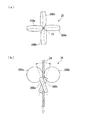
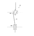
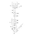
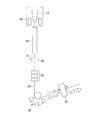
ここで、ねじれ付与装置26は、光ファイバ素線24に一定方向のねじれを連続して与える構成としたものであってもよいが、通常は、後に改めて説明するように、周期的にねじれの方向(時計方向かまたは反時計方向か)が反転されるように構成することが望ましい。その具体的構成は特に限定されるものではないが、例えば図2に示すようなねじれ付与装置(特許文献4の図11に示されるねじれ付与装置と同様のもの)、あるいは図3に示すようなねじれ付与装置(特許文献1の図2、特許文献4の図10に示されるねじれ付与装置と同様のもの)を適用すればよい。
Here, the
図2に示すねじれ付与装置26は、光ファイバ素線24をその両側から挟みながら回転する2組各一対のねじれ付与ローラ26Aa、26Ab;26Ba、26Bbによって構成されており、一方の組のねじれ付与ローラ26Aa、26Abの下流側に近接して、他方の組のねじれ付与ローラ26Ba、26Bbが前記一方の組のねじれ付与ローラ26Aa、26Abに対して90°ずれた位置に配置されている。そして各ねじれ付与ローラ26Aa、26Ab;26Ba、26Bbは、光ファイバ素線24をその両側から挟みながら、光ファイバ素線24の長さ方向(線引き方向)に直交する方向に対して所定の小角度だけ傾斜した軸線を中心として回転することによって、光ファイバ素線24にねじれを付与することができる。そして光ファイバ素線24に対する各ねじれ付与ローラ26Aa、26Ab;26Ba、26Bbの傾斜方向を反対方向に変えることによって、光ファイバ素線24に与えるねじれの方向を転換することができる。
The
また図3に示すねじれ付与装置26は、光ファイバ素線24が外周上に巻きかけられて、線引き方向に対して傾斜する回転軸を中心として回転するねじれ付与ローラ26Cと、その下流側に配設された、線引き方向に対して直交する回転軸を中心として回転する固定位置ローラ26Dとからなるものであり、光ファイバ素線24がねじれ付与ローラ26Cの外周上を回転軸線方向に沿って転動することによって光ファイバ素線24にねじれが付与され、かつねじれ付与ローラ26Cの傾斜方向を反転させるように揺動させることによって、ねじれ方向を反転させることができる。
Further, the
なお、ねじれ付与装置26の設置位置は、冷却・固化された光ファイバ裸線16を保護被覆用の硬化性樹脂により被覆してその硬化性樹脂が硬化した後にねじれを付与するように定めることが望ましい。ただし、そのねじれ付与装置26よりも上流側には、光ファイバ素線24もしくは光ファイバ裸線16に接してねじれの伝達を阻止するような機構、部材が存在しないようにすることが望ましい。そして図1に示す光ファイバ素線製造装置では、これらの条件を満たすべく、ねじれ付与装置26を、被覆硬化装置22とガイドローラ28との間の位置に配置している。この場合、ねじれ付与装置26よりも上流側では、硬化性被覆樹脂以外は、光ファイバ素線24もしくは光ファイバ裸線16の表面に物理的に接触する部材が存在しないため、ねじれ付与装置26により付与されたねじれをその上流側に連続的かつ円滑に伝搬させて、本発明で目的とする弾性ねじれ(ツイスト)を付与することが可能となる。但し、ある程度の溝幅を有する平溝プーリなど、光ファイバの転動が許容されるような部材であれば、その部材が接してもねじれの伝搬を阻害するおそれが少なく、そのような部材がねじれ付与装置26よりも上流側に存在することは許容される。
The installation position of the
また被覆装置20により被覆する硬化性樹脂は、1層でもよいが、一般には、一次被覆層(プライマリ材料)と二次被覆層(セカンダリ材料)との2層構造とすることが多く、本発明の場合も、2層構造の樹脂被覆層を形成することが望ましい。すなわち、一次被覆層として、エポキシアクリレート樹脂やウレタンアクリレート樹脂などの紫外線硬化性樹脂あるいはシリコン樹脂などの熱硬化性樹脂からなり、かつ硬化後のヤング率が5MPa程度以下の低ヤング率(一般には常温でのヤング率が0.3〜1,5MPa)のものを用いることが望ましく、一方二次被覆層としては、エポキシアクリレート樹脂やウレタンアクリレート樹脂などの紫外線硬化性樹脂あるいは変性シリコン樹脂などの熱硬化性樹脂からなり、かつ硬化後のヤング率が100MPa程度以上の高ヤング率(一般には常温でのヤング率が300〜1500MPa)のものを用いることが望ましい。このように一次被覆層として低ヤング率のものを用いることにより、光ファイバ裸線に対して良好なクッション効果を示すとともに、光ファイバ裸線に対する被覆層の密着性を高めることができ、一方、二次被覆層として、高ヤング率のものを用いることにより、外部からの損傷や摩擦、側圧などに対して十分に耐え得るようになるが、特に本発明の光ファイバ素線の場合、光ファイバ裸線部分に対する密着性を高めると同時に被覆層全体の見かけ上のヤング率を高めることが、被覆層により光ファイバ裸線部分の弾性ねじれ(ツイスト)を保持する上で有利となり、その観点からも、上述のように硬化後のヤング率が異なる2層構造の被覆層を形成することが望ましい。
The curable resin coated by the
なおこのような2層構造の被覆層を形成する場合の被覆方法および硬化方法としては、図1に示しているように、被覆装置20および被覆硬化装置22を1箇所のみに設けて、1基の被覆装置20により2層被覆を行なってその2層を3基の被覆硬化装置22により一括的に硬化させてもよく、あるいは後に説明する図8に示すように、被覆装置20および被覆硬化装置22をそれぞれ2箇所に設けて、一次被覆層の樹脂を被覆してそれを硬化させてから、二次被覆層の樹脂を被覆し、硬化させるようにしてもよい。
なおまた、光ファイバ裸線に硬化性樹脂を被覆する際の液体状態の樹脂の粘度も弾性ねじれ(ツイスト)の付与状況などに影響を与えるファクターであるが、それについては、後に項を改めて説明する。
As a coating method and a curing method for forming a coating layer having such a two-layer structure, as shown in FIG. The two layers may be coated by the
In addition, the viscosity of the resin in the liquid state when the curable resin is coated on the bare optical fiber is also a factor that affects the application of elastic twist (twist). This will be explained later. To do.
次に以上のような光ファイバ素線製造装置を用いて、本発明による弾性ねじれ(ツイスト)を付与した光ファイバ素線を製造する方法について説明する。 Next, a method for manufacturing an optical fiber with an elastic twist (twist) according to the present invention using the above-described optical fiber manufacturing apparatus will be described.
上述のような光ファイバ素線製造装置によって光ファイバ素線を製造するにあたっては、光ファイバ裸線の原料となる石英系ガラス母材などの光ファイバ母材12を紡糸用加熱炉14において2000℃以上の高温に加熱して溶融させ、その紡糸用加熱炉14の下部から、高温状態で光ファイバ裸線16として伸長させながら下方に引き出し、その光ファイバ裸線16を、冷却装置18により冷却して固化させる。冷却装置18により所要の温度まで冷却されて固化した光ファイバ裸線16には、例えば2層コーティング用の被覆装置20において紫外線硬化性樹脂や熱硬化性樹脂などの2種類の硬化性樹脂が液体状態で一次被覆層、二次被覆層として被覆され、さらにそれらの被覆樹脂が、被覆硬化装置22において加熱硬化あるいは紫外線硬化などの樹脂の種類に応じた適宜の硬化手段により硬化され、2層の被覆層を備えた光ファイバ素線24となり、引き続き、例えば図2あるいは図3に示したようなねじれ付与装置26によって、所定のねじれTW1、TW2が付与されてから、ガイドプーリ28を経て図示しない引取装置によって所定速度で引き取られ、さらに図示しない巻取装置により巻き取られる。
In manufacturing an optical fiber by the above-described optical fiber manufacturing apparatus, an
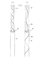
図1に示す装置において、ねじれ付与装置26により光ファイバ素線24に加えられたねじれTW1、TW2は、図1中の矢印Y1、Y2で示すように、ねじれ付与装置26の前後(上流側、下流側)に伝搬されていくが、ここでは、特に光ファイバ母材側(上流側)に伝搬していくねじれTW1について注目すると、そのねじれTW1は、被覆硬化装置22を経て被覆装置20を通り、さらにその上方の冷却装置18に向けて伝搬される。したがって、光ファイバ裸線16が冷却装置18により固化されてから、その裸線の外周上に被覆装置20により未硬化(液体状態)の硬化性樹脂が被覆され、さらにその被覆樹脂が被覆硬化装置22により硬化されるまでの間(図1の符号S1の領域付近)において、ねじれが加えられることになる。ここで光ファイバ裸線が固化してから加えられるねじれは、外力を解放すれば戻ってしまうねじれ、すなわち弾性ねじれ(ツイスト)となっている。一方、被覆樹脂の硬化後にねじれ付与装置26により光ファイバ素線24に加えられたねじれは、当然のことながら光ファイバ裸線部分と一体化された被覆層にも加えられるが、被覆装置20において液体状態で被覆されてからその樹脂が硬化するまでの間(図1の領域S2付近)においては、被覆樹脂は流動し得る状態であるため、弾性的な挙動はせず、したがってその間S2においては、被覆層には弾性ねじれが実質的に加えられないことになる。そして液体状態で光ファイバ裸線の外周上に被覆された樹脂が硬化する際に、それまでに加えられた光ファイバ裸線の弾性ねじれ(ツイスト)が、被覆層の樹脂によって固定される(保持される)ことになる。
In the apparatus shown in FIG. 1, the twists TW1 and TW2 applied to the
ここで、上述のような図1の装置により製造された光ファイバ素線24の製造過程における、被覆硬化装置22により被覆層が硬化された時点の段階での光ファイバ素線24の一例を、図4に模式的に示す。図4において、符号32Aは被覆層の一次被覆層、32Bは二次被覆層であり、また図4中の光ファイバ裸線16の外周上に描いた太い実線および破線は、付与されたねじれを表わしており、この図では、光ファイバ素線の製造時における下流側から見て時計方向のねじれが加えられて、光ファイバ裸線16の部分に、下側から見て時計方向のねじれを有する状態を示している。既に述べたように、被覆層32A、32Bは、光ファイバ裸線16の外周上に液体状態で被覆されてから硬化するまでの間は、弾性的な挙動を示さないから、図4に示す段階では、被覆層32A、32Bには実質的にねじれが与えられていない。但し、図4に示しているのは、次に説明するように、摩擦などの外力が解放されていない段階での光ファイバ素線であることに留意されたい。なおまた、被覆硬化装置22により被覆層が硬化されてからねじれ付与装置26に至る間においても光ファイバ素線にはねじれが加えられ、またねじれ付与装置26の下流側においても光ファイバ素線にねじれが加えられるが、これらの被覆層硬化後に加えられるねじれは、光ファイバ裸線部分および被覆層の両者に全体的に加えられる弾性ねじれであって、光ファイバ素線に対する摩擦などの外力が解放されれば、その分のねじれは解放されてしまい、外部的要因によるPMDの増加の抑制には確実ではなく、本発明の課題の解決に寄与しないから、ここではその詳細については説明を省略する。
Here, an example of the
ところで、硬化した被覆樹脂は、光ファイバ裸線部分よりも軟質でその剛性が低いから、前述のように光ファイバ裸線が固化してから被覆樹脂が硬化するまでの間において光ファイバ素線に弾性ねじれを付与しても、その弾性ねじれをそのまま完全に被覆樹脂によって固定すること、すなわち外力が解放されたときのねじれの弾性力による戻りを被覆樹脂によって完全に防止することは困難である。すなわち、ねじれを付与した光ファイバ素線について、その後に摩擦力などの外力が解放されてしまえば、光ファイバ素線の内部の光ファイバ裸線部分の弾性戻り力によって樹脂被覆層がその戻り方向にねじられ、ファイバ裸線部分の弾性ねじれもある程度戻ってしまうことは避けられない。しかしながら、硬化した被覆樹脂も弾性を有しているから、光ファイバ裸線部分のねじれが戻る際に被覆樹脂層に加わる戻り方向のねじれも弾性ねじれとして機能し、この被覆樹脂層の弾性ねじれに対する反発力と、光ファイバ裸線部分のねじれの戻りの力とが釣り合った状態で、光ファイバ裸線部分のねじれの戻りが停止することになる。したがって、外力が開放されたときの光ファイバ裸線部分のねじれの戻りは100%行なわれるのではなく、被覆樹脂の弾性反発力によって必ずある程度の割合で光ファイバ裸線部分のねじれが残る。このようにして残留したねじれ分が、被覆樹脂によって保持、固定され、最終使用形態の製品においても弾性ねじれ(ツイスト)として機能する。 By the way, since the cured coating resin is softer and less rigid than the bare optical fiber portion, it becomes an optical fiber strand until the coating resin is cured after the bare optical fiber is solidified as described above. Even if an elastic twist is applied, it is difficult to completely fix the elastic twist as it is with the coating resin, that is, to completely prevent the return due to the elastic force of the twist when the external force is released by the coating resin. That is, if an external force such as a frictional force is released after the twisted optical fiber strand, the resin coating layer returns to the return direction by the elastic return force of the bare optical fiber portion inside the optical fiber strand. It is inevitable that the elastic twisting of the bare fiber portion will return to some extent. However, since the cured coating resin has elasticity, the twist in the return direction applied to the coating resin layer when the twist of the bare optical fiber portion returns also functions as an elastic twist. In a state where the repulsive force and the twisting return force of the bare optical fiber portion are balanced, the twist return of the bare optical fiber portion stops. Therefore, when the external force is released, the twist of the bare optical fiber portion is not returned 100%, but the twist of the bare optical fiber portion always remains at a certain rate due to the elastic repulsive force of the coating resin. The remaining twisted portion is held and fixed by the coating resin, and functions as an elastic twist (twist) even in the product in the final use form.
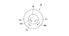
上述のように光ファイバ素線に対する摩擦などの外力が解放される際の力のバランスとねじれとの関係について、図5に模式的に示し、また光ファイバ素線に対する摩擦などの外力が解放された後のフリー状態の光ファイバ素線のねじれの状況を、図6の(b)に模式的に示す。なお比較のため、図6の(a)には、被覆層が硬化された直後の段階でのねじれ状況を示す(図4と実質的に同じ)。この図6(a)、(b)において太い実線、太い破線は、それぞれねじれの状況を示している。但しこれらの図5、図6においては、説明の簡略化のため、被覆層としては1層のもの(符号32)を示している。 FIG. 5 schematically shows the relationship between the force balance and torsion when the external force such as friction on the optical fiber is released as described above, and the external force such as friction on the optical fiber is released. FIG. 6B schematically shows the state of twisting of the optical fiber in the free state after the end. For comparison, FIG. 6A shows a twisted state immediately after the coating layer is cured (substantially the same as FIG. 4). In FIG. 6A and FIG. 6B, the thick solid line and the thick broken line indicate the twisted state. However, in these FIG. 5, FIG. 6, the thing of one layer (code | symbol 32) is shown as a coating layer for the simplification of description.
図5において、光ファイバ素線に対する外力が解放される直前までは、光ファイバ裸線16の部分に例えば反時計方向の弾性ねじれTP1が与えられているが、外力が解放されてフリー状態となる際には、時計方向に弾性復帰力F1が働き、反時計方向の弾性ねじれTP1が減少する。これは、時計方向に光ファイバ裸線16がねじられることを意味する。それに伴って、光ファイバ裸線16に密着している被覆層32も、時計方向にねじられることになる(ねじれTP2)。このとき、被覆層32も弾性を有しているため、時計方向ねじれTP2に対して反対方向(反時計方向)の弾性反発力F2が発生する。そして被覆層32の反時計方向の弾性反発力F2と、前述の光ファイバ裸線16の時計方向の弾性反発力F1とが釣り合った状態で、光ファイバ裸線16の部分の弾性ねじれTP1が保持される。したがって光ファイバ素線に対する摩擦などの外力が解放された後のフリー状態の光ファイバ素線においては、図6の(b)に示しているように、光ファイバ裸線16の部分と被覆層32の部分とでは、逆方向のねじれTP1、TP2が存在しており、光ファイバ裸線16の部分のねじれTP1は、被覆層硬化直後の段階でのねじれ(図6(a)の太い実線、破線)よりも小さい状態で残留していることになる。
In FIG. 5, until just before the external force on the optical fiber is released, for example, the counterclockwise elastic twist TP1 is given to the portion of the bare
ここで、硬化した被覆樹脂のヤング率は、一般に光ファイバガラスと比較してかなり低いが、ゼロではないから、外力解放時の光ファイバ裸線部分のねじれの戻りに伴う樹脂被覆層のねじれによる弾性反発力は必ず発生し、したがって上述のように反発力が釣り合った状態で、光ファイバ裸線部分の弾性ねじれが残留するのである。
一般的な光ファイバに使用されている2層構造の被覆層では、一次被覆層の樹脂(プライマリ材料)としては常温でのヤング率が0.3〜1.5MPa程度のものが用いられ、二次被覆層の樹脂(セカンダリ材料)としては常温でのヤング率が300〜1500MPa程度のものが用いられており、また光ファイバ裸線部分の径は125μm程度、被覆層の外径は、一次被覆層(プライマリ層)の外径は170〜210μm程度、二次被覆層(セカンダリ層)の外径は230〜260μm程度であり、このような光ファイバ素線について、前述のようにして弾性ねじれを付与し、その後外力を解放した状態で残留する光ファイバ裸線部分の弾性ねじれを調べたところ、付与したねじれの20〜30%程度の弾性ねじれが残ることが確認されている。
Here, although the Young's modulus of the cured coating resin is generally considerably lower than that of the optical fiber glass, it is not zero. Therefore, it is caused by the twist of the resin coating layer accompanying the return of the twist of the bare optical fiber portion when the external force is released. The elastic repulsive force is always generated. Therefore, the elastic twist of the bare optical fiber portion remains in the state where the repulsive force is balanced as described above.
In a coating layer having a two-layer structure used in a general optical fiber, a resin having a Young's modulus of about 0.3 to 1.5 MPa at room temperature is used as a resin (primary material) for a primary coating layer. As the resin (secondary material) for the secondary coating layer, one having a Young's modulus of about 300 to 1500 MPa at room temperature is used, the diameter of the bare optical fiber portion is about 125 μm, and the outer diameter of the coating layer is the primary coating. The outer diameter of the layer (primary layer) is about 170 to 210 μm, and the outer diameter of the secondary coating layer (secondary layer) is about 230 to 260 μm. Such an optical fiber is subjected to elastic twisting as described above. When the elastic torsion of the bare optical fiber portion remaining after the application of the external force was applied was examined, it was confirmed that an elastic twist of about 20 to 30% of the applied twist remained. .
また、ねじれ付与装置により光ファイバ素線に加えるねじれは、一方向に連続するものであってもよいが、既に述べたように、ねじれ方向を、時計方向、反時計方向に周期的に反転させることが、外部的要因によるPMDの増加抑制に対してより有効となる。 Further, the twist applied to the optical fiber by the twist applying device may be continuous in one direction, but as described above, the twist direction is periodically reversed clockwise and counterclockwise. This is more effective for suppressing the increase in PMD due to external factors.
このようにねじれ方向を周期的に反転させる場合、被覆装置で被覆する際の液体状態の被覆樹脂の粘度は、2層被覆の各被覆層を含め、0.1〜3Pa・secの範囲内であることが望ましい。被覆時の液体状態の樹脂の粘度が0.1Pa・sec未満では、粘度が低すぎるため、均一にコーティングして均一な膜厚の被覆層を得ることが困難となり、光ファイバ素線の被覆外径の変動量が±2μmを越えてしまい、光ファイバ素線として不良品となってしまうおそれがある。一方被覆時の液体状態の樹脂の粘度が3Pa・secを越えれば、ねじれ付与装置からその上流側へのねじれの伝搬に対して被覆樹脂の粘性が抵抗として作用し、その結果ねじれ付与装置と被覆装置との間でねじれが溜まる現象が顕著となってしまい、それに伴って被覆硬化装置と被覆装置との間へのねじれの伝搬も遅くなってしまう傾向を示す。その場合、ある方向(例えば時計方向)のねじれが被覆硬化装置と被覆装置との間で被覆層によって確実に保持される以前に、反対方向(例えば反時計方向)のねじれが伝搬されてきて、時計方向のねじれが戻されてしまい、結果的に被覆層硬化後に残るねじれが少なくなってしまうか、またはねじれがほぼ完全に消失してしまうおそれがある。したがって、ねじれ方向を周期的に反転させる場合には、被覆時の液体状態の樹脂の粘度を、上記のような適切な範囲内に調整することが望まれる。 When the twist direction is periodically reversed in this way, the viscosity of the coating resin in the liquid state when coating with the coating apparatus is within the range of 0.1 to 3 Pa · sec including each coating layer of the two-layer coating. It is desirable to be. If the viscosity of the resin in the liquid state at the time of coating is less than 0.1 Pa · sec, the viscosity is too low, making it difficult to coat uniformly and obtain a coating layer with a uniform film thickness. The variation in diameter exceeds ± 2 μm, which may result in a defective product as an optical fiber. On the other hand, if the viscosity of the resin in the liquid state at the time of coating exceeds 3 Pa · sec, the viscosity of the coating resin acts as a resistance against the propagation of twist from the twist imparting device to the upstream side. As a result, the twist imparting device and the coating The phenomenon that the twist is accumulated with the apparatus becomes remarkable, and accordingly, the propagation of the twist between the coating curing apparatus and the coating apparatus tends to be slow. In that case, the twist in the opposite direction (e.g. counterclockwise) has propagated before the twist in one direction (e.g. clockwise) is reliably held by the coating layer between the coating curing device and the coating device, As a result, the twist in the clockwise direction is returned, and as a result, the twist remaining after the coating layer is cured may be reduced or the twist may be almost completely lost. Therefore, when the twist direction is periodically reversed, it is desirable to adjust the viscosity of the resin in the liquid state at the time of coating within the appropriate range as described above.
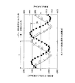
また前述のようにねじれ方向を周期的に反転させる場合、光ファイバ素線の長手方向の距離に対するねじれ角度(もしくは累積ねじれ角度)を、反転ねじれプロファイルとして描くことができ、その反転ねじれプロファイルの波形は、一般には正弦波状とすればよいが、その他、三角波状、あるいは台形波状など、特に限定されるものではない。正弦波を採用した場合の反転ねじれプロファイルの一例を図7に示す。図7において、実線は光ファイバ素線の長手方向の距離に対するねじれ角(単位長さあたりのねじれ角度)の推移を示し、破線は光ファイバ素線の長手方向の距離に対する累積ねじれ角度の推移を示す。 Also, when the twist direction is periodically reversed as described above, the twist angle (or cumulative twist angle) with respect to the distance in the longitudinal direction of the optical fiber can be drawn as a reverse twist profile, and the waveform of the reverse twist profile. Is generally sine wave, but is not particularly limited to triangular wave or trapezoidal wave. An example of the inverted twist profile when a sine wave is employed is shown in FIG. In FIG. 7, the solid line shows the transition of the twist angle (twist angle per unit length) with respect to the longitudinal distance of the optical fiber, and the broken line shows the transition of the cumulative twist angle with respect to the longitudinal distance of the optical fiber. Show.
ここで、反転ねじれプロファイルにおいて、ねじれの反転周期(ある方向、たとえば時計方向へのねじれが開始されて、その時計方向でのねじれが付与された後、ねじれ方向が反転されて、反時計方向にねじれが付与され、その反時計方向のねじれが終了するまでの、光ファイバ素線上での長さ)Tは、5〜30mの範囲内が好ましい。ねじれの反転周期Tが5m未満では、時計方向のねじれと反時計方向のねじれが伝搬中に相殺されやすくなるおそれがあり、一方ねじれの反転周期Tが30mを越えれば、より多くのねじれを加えなければ外部的要因によるPMDの増加の抑制効果が得られなくなるおそれがある。 Here, in the reverse twist profile, the twist reverse cycle (a twist in a certain direction, for example, clockwise, is started and the twist in the clockwise direction is applied, and then the twist direction is reversed to counterclockwise. The length (T) on the optical fiber until the twist is imparted and the twist in the counterclockwise direction is completed is preferably in the range of 5 to 30 m. If the twist reversal period T is less than 5 m, the clockwise twist and the counterclockwise twist may be easily canceled during propagation. On the other hand, if the twist reversal period T exceeds 30 m, more twist is added. Otherwise, the effect of suppressing the increase in PMD due to external factors may not be obtained.
さらに、反転ねじれプロファイルにおいて、累積ねじれ角の最大振幅MA(図7参照)は、500×T〜4000T(°)の範囲内が望ましい。累積ねじれ角の最大振幅MAが500×T(°)未満では、光ファイバ素線に対する外力を解放した後に残留する光ファイバ裸線部分の弾性ねじれが少なくなって、外部的要因によるPMDの増加を抑制する効果が少なくなってしまう。一方、累積ねじれ角の最大振幅MAが4000×T(°)を越えれば、光ファイバ素線に対する外力を解放したときに光ファイバ裸線部分から被覆層に加えられる応力が大きすぎて、光ファイバ裸線部分と被覆層との間に剥離が生じたり、被覆層に割れが発生したりするおそれがある。 Furthermore, in the inverted twist profile, the maximum amplitude MA (see FIG. 7) of the cumulative twist angle is preferably in the range of 500 × T to 4000 T (°). When the maximum amplitude MA of the cumulative twist angle is less than 500 × T (°), the elastic twist of the bare optical fiber remaining after releasing the external force on the optical fiber is reduced, and the PMD increases due to external factors. The suppression effect will decrease. On the other hand, if the maximum amplitude MA of the cumulative torsion angle exceeds 4000 × T (°), the stress applied to the coating layer from the bare optical fiber portion when the external force on the optical fiber is released is too large, and the optical fiber There is a risk that peeling occurs between the bare wire portion and the coating layer, or cracks occur in the coating layer.
図8には、本発明の光ファイバ素線を製造するための装置の別の実施形態を示す。この図8に示す光ファイバ素線製造装置は、2層構造の被覆層を有する光ファイバ素線を製造するために、被覆装置および被覆硬化装置を、それぞれ2箇所に設置したものである。すなわち、紡糸用加熱炉14から引き出された光ファイバ裸線16を冷却、固化させるための冷却装置18の直下に一次被覆装置20Aを設置し、さらにその下流側に一次被覆硬化装置22Aを設置して、先ず一次被覆層の被覆、硬化を行い、さらに一次被覆硬化装置の下流に二次被覆装置20Bおよび二次被覆硬化装置22Bをその順に設置して、一次被覆層上に改めて二次被覆層の被覆、硬化を行い、その下流でねじれ付与装置26によりねじれを付与するように構成している。このように2層構造の被覆層を有する光ファイバ素線を製造するにあたって、2箇所で別々に被覆層を被覆、硬化する場合も、ねじれの付与、保持および残留については、図1に基づいて説明したものと同様であり、またその望ましい条件についても前記と同様である。
FIG. 8 shows another embodiment of an apparatus for manufacturing the optical fiber of the present invention. The optical fiber manufacturing apparatus shown in FIG. 8 has a coating apparatus and a coating curing apparatus installed at two locations in order to manufacture an optical fiber having a two-layer coating layer. That is, a
以下に本発明の実施例を、比較例とともに説明する。なお以下の実施例は、本発明の作用効果を明確化するためのものであって、実施例に記載された条件が本発明の技術的範囲を限定しないことはもちろんである。 Examples of the present invention will be described below together with comparative examples. In addition, the following examples are for clarifying the effect of this invention, and of course, the conditions described in the examples do not limit the technical scope of this invention.
〔実施例1〕
図1に示すような光ファイバ素線製造装置を用い、かつその製造装置内におけるねじれ付与装置として図3に示すような装置を用い、一般的なシングルモードファイバの特性を有する2層被覆構造の石英ガラス系光ファイバ素線を製造するにあたり、本発明に従って弾性ねじれ(ツイスト)を付与した光ファイバ素線を製造した。光ファイバ母材からの紡糸速度(線引き速度)は、2000mm/minとした。また被覆装置は、1箇所で2種類の被覆樹脂をコーティングする2層同時コーティング方式(wet on wet方式)を適用した。一次被覆層の樹脂(プライマリ材料)としては、UV硬化型ウレタンアクリレート系樹脂(硬化時のヤング率0.5MPa)を用い、二次被覆層の樹脂(セカンダリ材料)としては、UV硬化型ウレタンアクリレート系樹脂(硬化時のヤング率1000MPa)を用いた。またこれらの被覆時の液体樹脂の粘度は、ともに1Pa・secとし、被覆装置により塗布後、被覆硬化装置としてのUVランプによって硬化させた。ねじれは、被覆硬化装置によって被覆樹脂が硬化した直後に与えた。なおねじれ付与装置よりも上流側には、被覆樹脂以外は、光ファイバ素線に物理的に接触するものがないような状態で線引きした。
[Example 1]
Using an optical fiber manufacturing apparatus as shown in FIG. 1, and using an apparatus as shown in FIG. 3 as a twist imparting apparatus in the manufacturing apparatus, a two-layer coating structure having the characteristics of a general single mode fiber is used. In manufacturing the silica glass-based optical fiber, an optical fiber having an elastic twist (twist) was manufactured according to the present invention. The spinning speed (drawing speed) from the optical fiber preform was 2000 mm / min. Moreover, the coating apparatus applied the 2 layer simultaneous coating system (wet on wet system) which coats two types of coating resin in one place. As a resin (primary material) for the primary coating layer, a UV curable urethane acrylate resin (Young's modulus at curing 0.5 MPa) is used, and as a resin (secondary material) for the secondary coating layer, a UV curable urethane acrylate. System resin (Young's modulus at the time of curing 1000 MPa) was used. In addition, the viscosity of the liquid resin at the time of coating was 1 Pa · sec, and after being applied by a coating apparatus, it was cured by a UV lamp as a coating curing apparatus. Twist was applied immediately after the coating resin was cured by the coating curing device. It should be noted that the wire was drawn in a state where there was no thing physically contacting the optical fiber, except for the coating resin, on the upstream side of the twist imparting device.
ここで、ねじれ付与装置により光ファイバ素線に付与するねじれは、そのプロファイルとして、ねじれ方向を周期的に逆転させる正弦波とし、周期Tが20m、累積ねじれ角の最大振幅MAが10000°となるようにねじれ付与装置の揺動角度、揺動速度の設定を行なった。ねじれ付与装置を通過後の光ファイバ素線は、ガイドプーリを経て引取機によって引き取り、さらにダンサープーリを経て巻取機により巻き取り、光ファイバ裸線部分に弾性ねじれ(ツイスト)が付与されている光ファイバ素線を得た。なお仕上がった光ファイバ素線は、裸線の直径125μm、被覆外径のプライマリ径(一次被覆層外径)は200μm、セカンダリ径(二次被覆層外径)は250μmであった。 Here, the twist imparted to the optical fiber by the twist imparting device is a sine wave that periodically reverses the twist direction, the period T is 20 m, and the maximum amplitude MA of the cumulative torsion angle is 10,000 °. In this way, the swing angle and swing speed of the twist imparting device were set. The optical fiber after passing through the twist applying device is taken up by a take-up machine through a guide pulley, and further taken up by a take-up machine through a dancer pulley, and an elastic twist (twist) is applied to the bare portion of the optical fiber. An optical fiber was obtained. The finished optical fiber had a bare wire diameter of 125 μm, a coating outer diameter primary diameter (primary coating layer outer diameter) of 200 μm, and a secondary diameter (secondary coating layer outer diameter) of 250 μm.
以上のようにして製造されて巻き取られた実施例1の光ファイバ素線について、プーリなど、摩擦抵抗などの外力が加わる部材に接しない距離(フリー長)を30m確保しながら、巻き返し装置により巻き返して、光ファイバ素線に加えられているねじれを解放させ、サンプルとした。そのサンプルについて、400mmφの鉄製ボビンに、巻き張力200gfで、1000mの長さを、ファイバ同士が重ならないように1層で強制的に巻き付けることにより、光ファイバ素線に意図的に側圧を加えた。すなわち外部的要因によりPMDが生じやすい条件とした。その後、ファイバ温度の安定化のため1時間以上放置してから、PMD測定を実施した。PMD測定には、ヒューレットパッカード製のHP8509B測定器を使用し、JME法(Jones Matrix Eigenanalysis法)により行なった。測定波長は1510〜1600nmとし、2nmステップでスキャンした。その結果、側圧付加時のPMD値(PMD1)として、0.05ps/√kmと、極めて小さい値が得られた。一方、同一素線をフリーコイル状態(側圧除去状態)として、上記と同様の条件で再度PMDを測定したところ、フリー状態のPMD値(PMD2)として、0.02ps/√kmの値が得られた。ここで、PMD1とPMD2との差分(0.03ps/√km)が、側圧付加によるPMD増加分、すなわち外部的要因によるPMD増加分とみなすことができる。
このように側圧付加時(外部的要因)のPMD増加が著しく少ないことは、素線製造過程中で付加したねじれが、前述の巻き返しによってフリー状態(外力解放状態)となった後にも、かなりの割合で被覆層により保持されて弾性ねじれ(ツイスト)として残留し、その残留弾性ねじれによって、側圧付加時(外部的要因)のPMD増加を抑制できたもの、と解される。
About the optical fiber strand of Example 1 manufactured and wound as described above, a rewinding device is used while securing a distance (free length) of 30 m that does not contact a member such as a pulley to which an external force such as friction resistance is applied. The sample was wound to release the twist applied to the optical fiber, and a sample was obtained. For the sample, a side pressure was intentionally applied to the optical fiber by forcibly winding a length of 1000 m on a 400 mmφ iron bobbin with a winding tension of 200 gf so that the fibers do not overlap each other. . That is, the conditions are such that PMD is likely to occur due to external factors. Then, PMD measurement was performed after leaving it to stand for 1 hour or more for stabilization of fiber temperature. The PMD measurement was performed by the JME method (Jones Matrix Eigenanalysis method) using an HP 8509B measuring instrument manufactured by Hewlett-Packard. The measurement wavelength was 1510 to 1600 nm, and scanning was performed in 2 nm steps. As a result, a very small value of 0.05 ps / √km was obtained as the PMD value (PMD1) when the side pressure was applied. On the other hand, when PMD was measured again under the same conditions as above with the same wire in the free coil state (side pressure removed state), a value of 0.02 ps / √km was obtained as the PMD value (PMD2) in the free state. It was. Here, the difference (0.03 ps / √km) between PMD1 and PMD2 can be regarded as an increase in PMD due to the addition of lateral pressure, that is, an increase in PMD due to an external factor.
Thus, the PMD increase at the time of applying side pressure (external factor) is remarkably small, even after the twist added during the manufacturing process of the wire becomes free (external force released) due to the aforementioned rewinding. It is understood that it is retained by the coating layer at a ratio and remains as an elastic twist (twist), and the residual elastic twist can suppress an increase in PMD when a side pressure is applied (external factor).
〔比較例1〕
弾性ねじれ(ツイスト)を付与しないこと以外は、実施例1と同様にして光ファイバ素線を製造した。そして実施例1と同様に、意図的に側圧を付与した状態、および側圧を除去したフリーコイル状態での、それぞれのPMD値を測定した。側圧を付与した状態でのPMD値(PMD1)は、0.62ps/√kmと、著しく高い値となってしまった。なお側圧除去状態(フリー状態)でのPMD値(PMD2)は、実施例1と同様に0.02ps/√kmであった。この場合のPMD1とPMD2との差分、すなわち側圧付加の外部的要因によるPMD増加分は、0.60ps/√kmと大きな値であった。
[Comparative Example 1]
An optical fiber was manufactured in the same manner as in Example 1 except that no elastic twist (twist) was applied. In the same manner as in Example 1, each PMD value was measured in a state where the side pressure was intentionally applied and in a free coil state where the side pressure was removed. The PMD value (PMD1) in the state where the side pressure was applied was an extremely high value of 0.62 ps / √km. Note that the PMD value (PMD2) in the side pressure removal state (free state) was 0.02 ps / √km, as in Example 1. In this case, the difference between PMD1 and PMD2, that is, the PMD increase due to the external factor of the lateral pressure application was a large value of 0.60 ps / √km.
上記のように弾性ねじれを付与した実施例1と、弾性ねじれを付与しない比較例1とを比較すれば、側圧付加時のPMD1は、比較例1の場合よりも実施例1の方が格段に小さく、PMD1とPMD2との差分(側圧付加によるPMD増加分)も、実施例1の方が比較例1よりも格段に小さい。このことから、比較例1では、弾性ねじれを付与しなかったために外部的要因によるPMD増加が大きくなってしまったのに対して、実施例1では、前述のように弾性ねじれを付与して、外力(側圧)解除後も弾性ねじれが保持されることによって、外部的要因によるPMDの増加を、きわめてわずかな量に抑えることができたことが明らかである。 Comparing Example 1 with elastic twist as described above and Comparative Example 1 without elastic twist, PMD1 when applying a side pressure is much stronger in Example 1 than in Comparative Example 1. The difference between PMD1 and PMD2 (PMD increase due to the addition of side pressure) is much smaller in Example 1 than in Comparative Example 1. From this, in Comparative Example 1, the PMD increase due to an external factor was increased because the elastic twist was not applied, whereas in Example 1, the elastic twist was applied as described above, It is clear that the increase in PMD due to external factors can be suppressed to a very small amount by maintaining the elastic twist even after the external force (side pressure) is released.
〔比較例2〕
図9に示すように、ねじれ付与装置26を引取キャプスタン36の下流に設置して、引取キャプスタン36を通過した後の光ファイバ素線24にねじれを付与した。その他の点は実施例1と同様である。製造された光ファイバ素線について、実施例1と同様に巻き返して、光ファイバ素線に加えられているねじれを解放させ、サンプルとした。そのサンプルについて、実施例1と同様に、意図的に側圧を付与した状態、および側圧を除去したフリーコイル状態での、それぞれのPMD値を測定した。側圧を付与した状態でのPMD値(PMD1)は、0.58ps/√kmと、著しく高い値となってしまった。なお側圧除去状態(フリー状態)でのPMD値(PMD2)は、0.016ps/√kmであった。この場合のPMD1とPMD2との差分、すなわち側圧付加の外部的要因によるPMD増加分は、約0.56ps/√kmであった。このように比較例2の場合は、PMD1値が比較例1と近い値となり、PMD1とPMD2との差分、すなわち外部的要因によるPMDの増加分も、比較例1に近い大きな値となってしまった。このことは、比較例2による光ファイバ素線では、その製造過程でねじれを付加しながらも、外部的要因によるPMDの増加の抑制が、十分に行なわれなかったことを意味する。これは、引取キャプスタン36の下流側でねじれを付加したため、引取キャプスタン36がねじれの伝搬に対する抵抗となって、そのねじれが引取キャプスタン36よりも上流側に十分に伝搬されず、そのため引取キャプスタン36の上流側に位置する被覆装置20から被覆硬化装置22の間付近では光ファイバ裸線にねじれが付与されず、結果的に光ファイバ素線に残留する弾性ねじれがほぼ零に近くなってしまったためと解される。
[Comparative Example 2]
As shown in FIG. 9, the
〔実施例2〕
図8に示すような光ファイバ素線製造装置を用い、かつその製造装置内におけるねじれ付与装置26として図3に示すような装置を用い、一般的なシングルモードファイバの特性を有する石英ガラス系光ファイバ素線を製造するにあたり、本発明に従って弾性ねじれ(ツイスト)を付与した2層被覆構造の光ファイバ素線を製造した。光ファイバ母材からの紡糸速度(線引き速度)は、1500mm/minとした。被覆―硬化方式としては、図8に示しているように、2箇所でそれぞれ別の被覆樹脂をコーティングする方式(wet on dry方式)を適用した。一次被覆層の樹脂(プライマリ材料)としては、UV硬化型ウレタンアクリレート系樹脂(硬化時のヤング率1.0MPa)を用い、二次被覆層の樹脂(セカンダリ材料)としては、UV硬化型ウレタンアクリレート系樹脂(硬化時のヤング率500MPa)を用いた。またこれらの被覆時の液体樹脂の粘度は、プライマリ材料は3Pa・sec、セカンダリ材料は0.1Pa・secとし、一次被覆装置20Aにより液体状態のプライマリ材料を被覆した後、一次被覆硬化装置22AとしてのUVランプによって硬化させてから、二次被覆装置20Bによりセカンダリ材料を被覆して、二次被覆硬化装置22BとしてのUVランプによって硬化させた。ねじれは、二次被覆硬化装置22Bによってセカンダリ材料が硬化した直後に与えた。なおねじれ付与装置26よりも上流側については、被覆樹脂以外は光ファイバ素線に物理的に接触するものがないような状態で線引きした。
[Example 2]
A quartz glass-based light having the characteristics of a general single-mode fiber using an optical fiber manufacturing apparatus as shown in FIG. 8 and an apparatus as shown in FIG. 3 as a
ここで、ねじれ付与装置26により光ファイバ素線24に付与するねじれは、そのプロファイルとして、ねじれ方向を周期的に反転させる三角波とし、周期Tが5m、累積ねじれ角の最大振幅MAが2500°となるように、ねじれ付与装置の揺動角度、揺動速度の設定を行なった。ねじれ付与装置26を通過後の光ファイバ素線24は、ガイドプーリ28を経て図示しない引取機によって引き取り、さらにダンサープーリを経て巻取機により巻き取った。仕上がった光ファイバ素線は、裸線の直径125μm、被覆外径のプライマリ径(一次被覆層外径)は190μm、セカンダリ径(二次被覆層外径)は240μmであった。
Here, the twist imparted to the
以上のようにして製造されて巻き取られた実施例2の光ファイバ素線について、プーリなどの部材に物理的に接しない距離(フリー長)を10m確保しながら、巻き返し装置により巻き返して、光ファイバ素線に加えられているねじれを解放させ、サンプルとした。そのサンプルについて、実施例1と同様に光ファイバ素線に意図的に側圧を加えた。すなわち外部的要因によりPMDが生じやすい条件とし、実施例1と同様にしてPMD測定を実施した。その結果、側圧付加時のPMD値(PMD1)として、0.08ps/√kmと、極めて小さい値が得られた。一方、同一素線をフリーコイル状態(側圧除去状態)として、上記と同様の条件で再度PMDを測定したところ、フリー状態のPMD値(PMD2)として、0.01ps/√kmの値が得られた。ここで、PMD1とPMD2との差分は、0.07ps/√kmときわめて小さい値に抑えることができた。したがって2層被覆構造の光ファイバ素線を製造する場合に、2箇所で被覆、硬化を行なっても、側圧付加、すなわち外部的要因によるPMD増加が著しく少ない光ファイバ素線が得られることが確認された。 About the optical fiber strand of Example 2 manufactured and wound up as mentioned above, it is rewound by a rewinding device while securing a distance (free length) that is not physically in contact with a member such as a pulley. The twist applied to the fiber was released to prepare a sample. For the sample, a side pressure was intentionally applied to the optical fiber as in Example 1. In other words, PMD measurement was carried out in the same manner as in Example 1 under conditions where PMD was likely to occur due to external factors. As a result, a very small value of 0.08 ps / √km was obtained as the PMD value (PMD1) when the side pressure was applied. On the other hand, when PMD was measured again under the same conditions as above with the same wire in the free coil state (side pressure removed state), a value of 0.01 ps / √km was obtained as the PMD value (PMD2) in the free state. It was. Here, the difference between PMD1 and PMD2 could be suppressed to an extremely small value of 0.07 ps / √km. Therefore, when manufacturing an optical fiber with a two-layer coating structure, it is confirmed that even if coating and curing are performed at two locations, an optical fiber can be obtained in which side pressure is applied, that is, PMD increase due to external factors is extremely small. It was done.
〔実施例3〕
実施例2と同様にして、弾性ねじれ(ツイスト)を付加しながら、2層被覆構造の光ファイバ素線を製造した。被覆樹脂の被覆時(液体状態)の粘度は、実施例2と同じくプライマリ材料は3Pa・sec、セカンダリ材料は0.1Pa・secとした。ねじれ付与装置により光ファイバ素線に付与するねじれは、そのプロファイルとして、ねじれ方向を周期的に逆転させる台形波とし、周期Tが30m、累積ねじれ角の最大ねじれ角MAが120000°となるようにねじれ付与装置の揺動角度、揺動速度の設定を行なった。ねじれ付与装置を通過後の光ファイバ素線は、引取機によって引き取り、さらにダンサープーリを経て巻取機により巻き取った。仕上がった光ファイバ素線は、裸線の直径125μm、被覆外径のプライマリ径は180μm、セカンダリ径は260μmであった。
Example 3
In the same manner as in Example 2, an optical fiber having a two-layer coating structure was manufactured while adding an elastic twist (twist). The viscosity at the time of coating with the coating resin (liquid state) was 3 Pa · sec for the primary material and 0.1 Pa · sec for the secondary material as in Example 2. The twist imparted to the optical fiber by the twist imparting device is a trapezoidal wave that periodically reverses the twist direction, and the period T is 30 m, and the maximum twist angle MA of the cumulative twist angle is 120,000 °. The swing angle and swing speed of the twist imparting device were set. The optical fiber after passing through the twist imparting device was taken up by a take-up machine, and further taken up by a winder through a dancer pulley. The finished optical fiber had a bare wire diameter of 125 μm, a primary outer diameter of 180 μm, and a secondary diameter of 260 μm.
以上のようにして製造されて巻き取られた実施例3の光ファイバ素線について、プーリなどの部材に物理的に接しない距離(フリー長)を40m確保しながら、巻き返し装置により巻き返して、光ファイバ素線に加えられているねじれを解放させ、サンプルとした。そのサンプルについて、実施例1と同様に光ファイバ素線に意図的に側圧を加えた。すなわち外部的要因によりPMDが生じやすい条件とし、実施例1と同様にしてPMD測定を実施した。その結果、側圧付加時のPMD値(PMD1)として、0.06ps/√kmと、極めて小さい値が得られた。一方、同一素線をフリーコイル状態(側圧除去状態)として、上記と同様の条件で再度PMDを測定したところ、フリー状態のPMD値(PMD2)として、0.03ps/√kmの値が得られた。ここで、PMD1とPMD2との差分は、0.03ps/√kmときわめて小さい値に抑えることができた。したがってこの実施例3により得られた光ファイバ素線も、側圧付加、すなわち外部的要因によるPMD増加を著しく小さく抑え得ることが確認された。 About the optical fiber strand of Example 3 manufactured and wound up as described above, it is rewound by a rewinding device while securing a distance (free length) that is not physically in contact with a member such as a pulley. The twist applied to the fiber was released to prepare a sample. For the sample, a side pressure was intentionally applied to the optical fiber as in Example 1. In other words, PMD measurement was carried out in the same manner as in Example 1 under conditions where PMD was likely to occur due to external factors. As a result, a very small value of 0.06 ps / √km was obtained as the PMD value (PMD1) when the side pressure was applied. On the other hand, when PMD was measured again under the same conditions as above with the same wire in the free coil state (side pressure removed state), a value of 0.03 ps / √km was obtained as the PMD value (PMD2) in the free state. It was. Here, the difference between PMD1 and PMD2 could be suppressed to an extremely small value of 0.03 ps / √km. Therefore, it was confirmed that the optical fiber obtained by Example 3 can also suppress the PMD increase due to the lateral pressure, that is, the external factor, to be extremely small.
〔比較例3〕
実施例3と同様にして、弾性ねじれ(ツイスト)を付加しながら、2層被覆構造の光ファイバ素線を製造した。被覆樹脂の被覆時の粘度は、プライマリ材料は3.5Pa・sec、セカンダリ材料は0.5Pa・secとした。ねじれ付与装置により光ファイバ素線に付与するねじれは、そのプロファイルとして、ねじれ方向を周期的に逆転させる三角波とし、周期Tが5m、累積ねじれ角の最大振幅MAが2500°となるようにねじれ付与装置の揺動角度、揺動速度の設定を行なった。ねじれ付与装置を通過後の光ファイバ素線は、引取機によって引き取り、さらにダンサープーリを経て巻取機により巻き取った。仕上がった光ファイバ素線は、裸線の直径125μm、被覆外径のプライマリ径は180μm、セカンダリ径は260μmであった。
[Comparative Example 3]
In the same manner as in Example 3, an optical fiber having a two-layer coating structure was manufactured while adding an elastic twist (twist). The viscosity at the time of coating with the coating resin was 3.5 Pa · sec for the primary material and 0.5 Pa · sec for the secondary material. The twist imparted to the optical fiber by the twist imparting device is a triangular wave that periodically reverses the twist direction, and the twist is imparted so that the period T is 5 m and the maximum amplitude MA of the cumulative twist angle is 2500 °. The swing angle and swing speed of the device were set. The optical fiber after passing through the twist imparting device was taken up by a take-up machine, and further taken up by a winder through a dancer pulley. The finished optical fiber had a bare wire diameter of 125 μm, a primary outer diameter of 180 μm, and a secondary diameter of 260 μm.
以上のようにして製造されて巻き取られた比較例3の光ファイバ素線について、プーリなどの部材に物理的に接しない距離(フリー長)を10m確保しながら、巻き返し装置により巻き返して、光ファイバ素線に加えられているねじれを解放させ、サンプルとした。そのサンプルについて、実施例1と同様に光ファイバ素線に意図的に側圧を加えた。すなわち外部的要因によりPMDが生じやすい条件とし、実施例1と同様にしてPMD測定を実施した。その結果、側圧付加時のPMD値(PMD1)は、0.25ps/√kmと、弾性ねじれ(ツイスト)を付加しない場合よりは小さいが、実施例3の場合よりも大きい値となった。なお同一素線をフリーコイル状態(側圧除去状態)として、上記と同様の条件で再度PMDを測定したところ、フリー状態のPMD値(PMD2)として、0.025ps/√kmの値が得られた。ここで、PMD1とPMD2との差分は、約0.22ps/√kmと、比較例1や比較例2の場合よりは少ないものの、実施例3の場合よりは大きい値となった。これは、一次被覆層の樹脂(プライマリ材料)の被覆時の粘度が高かったため、ねじりの伝搬およびねじれ方向の反転が阻害され、UV照射によるプライマリ材料の硬化前にねじれが相殺され、結果的に被覆後の光ファイバ素線に残留するねじれが少なくなってしまったものと解される。 About the optical fiber strand of the comparative example 3 manufactured and wound up as mentioned above, it is rewound by a rewinding device while securing a distance (free length) that is not physically in contact with a member such as a pulley. The twist applied to the fiber was released to prepare a sample. For the sample, a side pressure was intentionally applied to the optical fiber as in Example 1. In other words, PMD measurement was carried out in the same manner as in Example 1 under conditions where PMD was likely to occur due to external factors. As a result, the PMD value (PMD1) when the side pressure was applied was 0.25 ps / √km, which was smaller than when no elastic twist (twist) was added, but larger than that in Example 3. When PMD was measured again under the same conditions as above with the same wire in the free coil state (side pressure removed state), a free state PMD value (PMD2) of 0.025 ps / √km was obtained. . Here, the difference between PMD1 and PMD2 was about 0.22 ps / √km, which was smaller than those in Comparative Examples 1 and 2, but larger than that in Example 3. This is because the viscosity at the time of coating the resin (primary material) of the primary coating layer was high, and thus the propagation of the twist and the reversal of the twist direction were hindered, and the twist was offset before the primary material was cured by UV irradiation. It is understood that the twist remaining in the coated optical fiber is reduced.
〔比較例4〕
実施例3と同様にして、弾性ねじれ(ツイスト)を付加しながら、2層被覆構造の光ファイバ素線を製造した。被覆時における液体状態の樹脂の粘度は、プライマリ材料は2.0Pa・sec、セカンダリ材料は0.05Pa・secとした。ねじれ付与装置により光ファイバ素線に付与するねじれは、そのプロファイルとして、ねじれ方向を周期的に反転させる三角波とし、周期Tが5m、累積ねじれ角の最大振幅MAが2500°となるようにねじれ付与装置の揺動角度、揺動速度の設定を行なった。ねじれ付与装置を通過後の光ファイバ素線は、引取機によって引き取り、さらにダンサープーリを経て巻取機により巻き取った。仕上がった光ファイバ素線は、裸線の直径125μm、被覆層の一次被覆層外径(プライマリ径)は180μm、二次被覆層外径(セカンダリ径)は260μmであったが、二次被覆層の外径(セカンダリ径)の変動が±5μmと著しく大きくなってしまった。これは、二次被覆層の樹脂(セカンダリ材料)の液体状態での粘度が低いため、コーティングが安定しなかったことが原因である。このような光ファイバ素線は、実用には不適当であるため、PMDの評価は実施しなかった。
[Comparative Example 4]
In the same manner as in Example 3, an optical fiber having a two-layer coating structure was manufactured while adding an elastic twist (twist). The viscosity of the resin in the liquid state during coating was 2.0 Pa · sec for the primary material and 0.05 Pa · sec for the secondary material. The twist imparted to the optical fiber by the twist imparting device is a triangular wave that periodically reverses the twist direction, and the twist is imparted so that the period T is 5 m and the maximum amplitude MA of the cumulative twist angle is 2500 °. The swing angle and swing speed of the device were set. The optical fiber after passing through the twist imparting device was taken up by a take-up machine, and further taken up by a winder through a dancer pulley. The finished optical fiber had a bare wire diameter of 125 μm, a primary coating layer outer diameter (primary diameter) of 180 μm, and a secondary coating layer outer diameter (secondary diameter) of 260 μm. The fluctuation of the outer diameter (secondary diameter) of this was significantly increased to ± 5 μm. This is because the coating was not stable because the viscosity of the resin (secondary material) of the secondary coating layer in the liquid state was low. Since such an optical fiber is not suitable for practical use, PMD was not evaluated.
〔比較例5〕
実施例1と同様にして、弾性ねじれ(ツイスト)を付加しながら、2層被覆構造の光ファイバ素線を製造した。但し、ねじれ付与のプロファイルは実施例1とは異ならしめた。すなわち、ねじれ付与装置により光ファイバ素線に付与するねじれは、そのプロファイルとして、ねじれ方向を周期的に逆転させる正弦波とし、周期Tが3m、累積ねじれ角の最大振幅MAが1500°となるように、ねじれ付与装置の揺動角度、揺動速度の設定を行なった。ねじれ付与装置を通過後の光ファイバ素線は、引取機によって引き取り、さらにダンサープーリを経て巻取機により巻き取った。仕上がった光ファイバ素線は、裸線の直径125μm、被覆外径のプライマリ径は200μm、セカンダリ径は250μmであった。
[Comparative Example 5]
In the same manner as in Example 1, an optical fiber having a two-layer coating structure was manufactured while adding an elastic twist (twist). However, the profile for imparting twist was different from that in Example 1. That is, the twist imparted to the optical fiber by the twist imparting device is a sine wave that periodically reverses the twist direction, the period T is 3 m, and the maximum amplitude MA of the cumulative twist angle is 1500 °. In addition, the swing angle and swing speed of the twist imparting device were set. The optical fiber after passing through the twist imparting device was taken up by a take-up machine, and further taken up by a winder through a dancer pulley. The finished optical fiber had a bare wire diameter of 125 μm, a primary outer diameter of 200 μm, and a secondary diameter of 250 μm.
以上のようにして製造された比較例5の光ファイバ素線について、プーリなどの部材に物理的に接しない距離(フリー長)を10m確保しながら、巻き返し装置により巻き返して、光ファイバ素線に加えられているねじれを解放させ、サンプルとした。そのサンプルについて、実施例1と同様に、意図的に側圧を加えた。すなわち外部的要因によりPMDが生じやすい条件として、PMD測定を実施した。その結果、側圧付加時のPMD値(PMD1)は、0.4ps/√kmと、比較例1、比較例2の場合よりは小さいものの、比較的大きな値となってしまった。なお同一素線をフリーコイル状態(側圧除去状態)として、上記と同様の条件で再度PMDを測定したところ、フリー状態のPMD値(PMD2)は、0.02ps/√kmであった。ここで、側圧付加時のPMD値(PMD1)が比較的大きい値となってしまったのは、光ファイバ素線に付与するツイストの周期が比較的短く、そのため付与したツイストが一部解放されて、残留するねじれが少なくなってしまったためと考えられる。但しこの場合でも、ツイストを全く付加しない場合よりも、側圧付加時のPMD値(PMD1)の増加分が少ないことはもちろんである。 About the optical fiber strand of the comparative example 5 manufactured as mentioned above, it was rewound by the rewinding device while securing a distance (free length) that is not physically in contact with a member such as a pulley, and turned into an optical fiber strand. The added twist was released and used as a sample. A side pressure was intentionally applied to the sample in the same manner as in Example 1. That is, PMD measurement was performed as a condition where PMD is likely to occur due to external factors. As a result, the PMD value (PMD1) when the side pressure was applied was 0.4 ps / √km, which was smaller than those of Comparative Examples 1 and 2, but was a relatively large value. When PMD was measured again under the same conditions as above with the same wire in the free coil state (side pressure removed state), the PMD value (PMD2) in the free state was 0.02 ps / √km. Here, the reason why the PMD value (PMD1) when the side pressure is applied becomes a relatively large value is that the period of twist applied to the optical fiber is relatively short, so that the applied twist is partially released. This is probably because the remaining twist has decreased. However, even in this case, as a matter of course, the increase in the PMD value (PMD1) when the lateral pressure is applied is smaller than when no twist is added.
〔比較例6〕
実施例1と同様にして、弾性ねじれ(ツイスト)を付加しながら、2層被覆構造の光ファイバ素線を製造した。但し、ねじれのプロファイルは実施例1とは異ならしめた。すなわち、ねじれ付与装置により光ファイバ素線に付与するねじれは、そのプロファイルとして、ねじれ方向を周期的に逆転させる正弦波とし、周期Tを15m、累積ねじれ角の最大振幅MAが65000°となるようにねじれ付与装置の揺動角度、揺動速度の設定を行なった。ねじれ付与装置を通過後の光ファイバ素線は、引取機によって引き取り、さらにダンサープーリを経て巻取機により巻き取った。仕上がった光ファイバ素線は、裸線の直径125μm、被覆外径のプライマリ径は200μm、セカンダリ径は250μmであった。
[Comparative Example 6]
In the same manner as in Example 1, an optical fiber having a two-layer coating structure was manufactured while adding an elastic twist (twist). However, the twist profile was different from that of Example 1. That is, the twist imparted to the optical fiber by the twist imparting device is a sine wave that periodically reverses the twist direction, the period T is 15 m, and the maximum amplitude MA of the cumulative twist angle is 65000 °. In addition, the swing angle and swing speed of the torsion imparting device were set. The optical fiber after passing through the twist imparting device was taken up by a take-up machine, and further taken up by a winder through a dancer pulley. The finished optical fiber had a bare wire diameter of 125 μm, a primary outer diameter of 200 μm, and a secondary diameter of 250 μm.
以上のようにして製造された比較例6の光ファイバ素線について、プーリなどの部材に物理的に接しない距離(フリー長)を30m確保しながら、巻き返し装置により巻き返して、光ファイバ素線に加えられているねじれを解放させ、サンプルとした。そのサンプルについて、実施例1と同様に、意図的に側圧を加えた。すなわち外部的要因によりPMDが生じやすい条件として、PMD測定を実施した。その結果、側圧付加時のPMD値(PMD1)は、0.04ps/√kmと低い値となった。なお同一素線をフリーコイル状態(側圧除去状態)として、上記と同様の条件で再度PMDを測定したところ、フリー状態のPMD値(PMD2)は、0.02ps/√kmであった。このように、比較例6でも側圧付加時のPMDの低減に有効であったが、光ファイバ素線を恒温槽に入れて−40℃〜+80℃のヒートサイクル試験を行なった後、被覆層を観察したところ、被覆層に割れが発生していることが認められた。これは、光ファイバに付与するねじれ量が大きすぎたため、被覆層に加わる応力が過大となり、割れの発生を招いてしまったためと解される。 About the optical fiber strand of the comparative example 6 manufactured as mentioned above, it rewinds with a rewinding device, securing 30m of distance (free length) which does not physically contact members, such as a pulley, and turns into an optical fiber strand. The added twist was released and used as a sample. A side pressure was intentionally applied to the sample in the same manner as in Example 1. That is, PMD measurement was performed as a condition where PMD is likely to occur due to external factors. As a result, the PMD value (PMD1) when the side pressure was applied was a low value of 0.04 ps / √km. When PMD was measured again under the same conditions as above with the same wire in the free coil state (side pressure removed state), the PMD value (PMD2) in the free state was 0.02 ps / √km. Thus, although it was effective in the reduction of PMD at the time of side pressure addition also in the comparative example 6, after putting an optical fiber strand into a thermostat and performing a heat cycle test of -40 degreeC-+80 degreeC, a coating layer is used. When observed, it was recognized that the coating layer was cracked. This is considered to be because the amount of twist applied to the optical fiber was too large, and the stress applied to the coating layer was excessive, leading to the occurrence of cracks.
10 光ファイバ素線製造装置
12 光ファイバ母材
14 紡糸用加熱炉
16 光ファイバ裸線
18 冷却装置
20 被覆装置
22 被覆硬化装置
24 光ファイバ素線
26 ねじれ付与装置
DESCRIPTION OF
Claims (1)
前記ファイバ裸線に硬化性樹脂を被覆するにあたり、その液体状態の樹脂の被覆時の粘度を、0.1〜3Pa・secの範囲内とし、
前記ねじれ付与装置により光ファイバ素線にねじれを付与するにあたり、ねじれの方向を周期的に反転させ、かつその際に光ファイバ素線に付与するねじれの反転周期Tを、光ファイバ素線の長手方向の距離に関して、5〜30mの範囲内とし、かつその反転ねじれプロファイルとして、累積ねじれ角の最大振幅を、500×T(°)〜4000×T(°)の範囲内とし、
かつ前記ねじれ付与装置よりも上流側に、光ファイバ素線のねじれの伝搬を阻止する部材が存在しない状態でねじれを付与し、
前記ねじれ付与装置により光ファイバ素線に付与されたねじれが、ねじれ付与装置の上流側に伝搬されて、樹脂被覆前でかつ固化後の光ファイバ裸線に弾性ねじれが付与されるとともに、その弾性ねじれが付与された状態の光ファイバ裸線が、液体状態の硬化性樹脂で被覆されてその被覆樹脂が硬化することにより、被覆層によって光ファイバ裸線の弾性ねじれが保持されて、付与されたねじれの20〜30%が外力解放後に残るようにしたことを特徴とする光ファイバ素線の製造方法。 The optical fiber preform is heated and melted to draw an optical fiber bare wire of a predetermined diameter. After the bare optical fiber is solidified, the outer periphery is coated with a liquid curable resin, and the resin is further cured. Then, as an optical fiber strand, a twist is imparted to the optical fiber strand by a twist imparting device, and the optical fiber strand is pulled after the twist is imparted,
In coating the curable resin on the bare fiber, the viscosity at the time of coating the resin in the liquid state is in the range of 0.1 to 3 Pa · sec,
When the twist is applied to the optical fiber by the twist applying device, the twist direction is periodically reversed and the twist inversion period T applied to the optical fiber at that time is set to the longitudinal direction of the optical fiber. With respect to the distance in the direction, it is within the range of 5 to 30 m, and the maximum amplitude of the cumulative torsion angle is within the range of 500 × T (°) to 4000 × T (°) as its inverted twist profile,
And on the upstream side of the twist imparting device, the twist is imparted in a state where there is no member that prevents the propagation of the twist of the optical fiber,
The twist imparted to the optical fiber by the twist imparting device is propagated to the upstream side of the twist imparting device, and an elastic twist is imparted to the bare optical fiber before the resin coating and after solidification, and its elasticity The bare optical fiber in a twisted state is coated with a curable resin in a liquid state, and the coating resin is cured, so that the elastic twist of the bare optical fiber is held by the coating layer and applied. method for manufacturing an optical fiber you characterized in that 20-30% of the twist is to remain after the external force releases.
Priority Applications (3)
| Application Number | Priority Date | Filing Date | Title |
|---|---|---|---|
| JP2011028387A JP5778939B2 (en) | 2011-02-14 | 2011-02-14 | Manufacturing method of optical fiber |
| CN201210027643.6A CN102636837B (en) | 2011-02-14 | 2012-02-08 | Optical fiber and method and apparatus for manufacturing optical fiber |
| US13/372,128 US8857221B2 (en) | 2011-02-14 | 2012-02-13 | Optical fiber and method and apparatus for manufacturing optical fiber |
Applications Claiming Priority (1)
| Application Number | Priority Date | Filing Date | Title |
|---|---|---|---|
| JP2011028387A JP5778939B2 (en) | 2011-02-14 | 2011-02-14 | Manufacturing method of optical fiber |
Publications (2)
| Publication Number | Publication Date |
|---|---|
| JP2012168310A JP2012168310A (en) | 2012-09-06 |
| JP5778939B2 true JP5778939B2 (en) | 2015-09-16 |
Family
ID=46621293
Family Applications (1)
| Application Number | Title | Priority Date | Filing Date |
|---|---|---|---|
| JP2011028387A Active JP5778939B2 (en) | 2011-02-14 | 2011-02-14 | Manufacturing method of optical fiber |
Country Status (3)
| Country | Link |
|---|---|
| US (1) | US8857221B2 (en) |
| JP (1) | JP5778939B2 (en) |
| CN (1) | CN102636837B (en) |
Cited By (1)
| Publication number | Priority date | Publication date | Assignee | Title |
|---|---|---|---|---|
| US11377384B2 (en) | 2017-01-19 | 2022-07-05 | University Of Bath | Method of making an imaging fibre apparatus and optical fibre apparatus with different core |
Families Citing this family (10)
| Publication number | Priority date | Publication date | Assignee | Title |
|---|---|---|---|---|
| FR2967155B1 (en) * | 2010-11-08 | 2017-12-15 | Delachaux Sa | IMPROVED OPTICAL FIBER GUIDING DEVICE |
| CN103969738B (en) * | 2013-01-28 | 2017-06-06 | 无锡万润光子技术有限公司 | Based on inclined hole melting-embedding core vortex optical fiber of spiral and preparation method thereof |
| CN103969739B (en) * | 2013-01-28 | 2018-05-11 | 无锡万润光子技术有限公司 | Vortex optical fiber based on linear refractive index distribution and preparation method thereof |
| CN103969737B (en) * | 2013-01-28 | 2017-04-12 | 无锡万润光子技术有限公司 | Asymmetric birefringence vortex fiber and manufacturing method of asymmetric birefringence vortex fiber |
| JP6451319B2 (en) * | 2013-04-12 | 2019-01-16 | 住友電気工業株式会社 | Coated optical fiber |
| US10081563B2 (en) * | 2015-09-23 | 2018-09-25 | Johns Manville | Systems and methods for mechanically binding loose scrap |
| CN110563322B (en) * | 2019-09-10 | 2024-01-23 | 泰安佳成机电科技有限公司 | Glass fiber automatic yarn hanging system |
| GB201918628D0 (en) * | 2019-12-17 | 2020-01-29 | Lumenisity Ltd | Method for processing glass filament |
| CN111620560B (en) * | 2020-06-10 | 2021-11-09 | 长飞光纤光缆股份有限公司 | Drawn optical fiber twisting control device and method and multimode optical fiber |
| JP2023007731A (en) * | 2021-07-02 | 2023-01-19 | 住友電気工業株式会社 | Method and apparatus for manufacturing optical fiber |
Family Cites Families (21)
| Publication number | Priority date | Publication date | Assignee | Title |
|---|---|---|---|---|
| FR2515693B1 (en) * | 1981-11-03 | 1985-10-11 | Thomson Csf | METHOD FOR MANUFACTURING AN OBJECT HAVING A CHIRAL STRUCTURE ARISING FROM A SOURCE OF FORMABLE MATERIAL AND DEVICE USING THE SAME |
| FR2559275B1 (en) * | 1984-02-02 | 1988-04-08 | Thomson Csf | METHOD FOR MANUFACTURING AN OPTICAL FIBER WITH A CHIRAL STRUCTURE AND DEVICE CARRYING OUT THIS METHOD |
| US5298047A (en) * | 1992-08-03 | 1994-03-29 | At&T Bell Laboratories | Method of making a fiber having low polarization mode dispersion due to a permanent spin |
| JPH07168067A (en) * | 1993-12-15 | 1995-07-04 | Toshiba Corp | Optical fiber |
| JP3557606B2 (en) | 1995-03-01 | 2004-08-25 | 住友電気工業株式会社 | Optical fiber and method of manufacturing optical fiber |
| CN1113043C (en) * | 1995-08-16 | 2003-07-02 | 等离子光纤维股份有限公司 | Optical Fiber with Low Polarization Mode Dispersion |
| US6324872B1 (en) | 1996-04-12 | 2001-12-04 | Corning Incorporated | Method and apparatus for introducing controlled spin in optical fibers |
| JPH1010378A (en) * | 1996-06-25 | 1998-01-16 | Toshiba Corp | Optical fiber core, optical fiber coil, and method of manufacturing optical fiber core |
| KR20010071612A (en) * | 1998-06-24 | 2001-07-28 | 지아네시 피에르 지오반니 | Method and apparatus for manufacturing an optical fiber from a preform |
| CA2359033A1 (en) | 1999-01-27 | 2000-08-03 | Sumitomo Electric Industries, Ltd. | Method and apparatus for fabricating coated optical fiber, and coated optical fiber |
| US20030010066A1 (en) * | 2001-01-30 | 2003-01-16 | Eisuke Sasaoka | Method and apparatus for manufacturing optical fiber |
| EP1497686B1 (en) * | 2002-04-24 | 2015-03-04 | Prysmian S.p.A. | Method for controlling microbending induced attenuation losses in an optical fiber |
| US6859596B2 (en) * | 2002-07-23 | 2005-02-22 | Fitel Usa Corp. | Systems and methods for forming ultra-low PMD optical fiber using amplitude and frequency keyed fiber spin functions |
| JP2004175611A (en) * | 2002-11-26 | 2004-06-24 | Sumitomo Electric Ind Ltd | Method and apparatus for manufacturing optical fiber |
| BR0215997B1 (en) * | 2002-12-30 | 2012-05-29 | method for producing an optical fiber having low polarization mode dispersion. | |
| EP1701925B1 (en) * | 2003-08-29 | 2015-12-02 | Prysmian S.p.A. | Process for producing a low polarization mode dispersion optical fiber |
| US7317855B2 (en) * | 2004-12-16 | 2008-01-08 | Corning Incorporated | Method of imparting twist to optical fiber |
| JP2007077329A (en) * | 2005-09-15 | 2007-03-29 | Jsr Corp | Liquid curable resin composition |
| CN101960344B (en) | 2008-02-28 | 2013-06-05 | 住友电气工业株式会社 | Optical fiber |
| US8756906B2 (en) | 2008-06-05 | 2014-06-24 | Sumitomo Electric Industries, Ltd. | Coated optical fiber producing apparatus and coated optical fiber producing method |
| JP5212331B2 (en) | 2008-10-20 | 2013-06-19 | 住友電気工業株式会社 | Optical fiber manufacturing method and manufacturing apparatus |
-
2011
- 2011-02-14 JP JP2011028387A patent/JP5778939B2/en active Active
-
2012
- 2012-02-08 CN CN201210027643.6A patent/CN102636837B/en active Active
- 2012-02-13 US US13/372,128 patent/US8857221B2/en active Active
Cited By (2)
| Publication number | Priority date | Publication date | Assignee | Title |
|---|---|---|---|---|
| US11377384B2 (en) | 2017-01-19 | 2022-07-05 | University Of Bath | Method of making an imaging fibre apparatus and optical fibre apparatus with different core |
| US11577986B2 (en) | 2017-01-19 | 2023-02-14 | University Of Bath | Method of making an imaging fibre apparatus and optial fibre apparatus with different core |
Also Published As
| Publication number | Publication date |
|---|---|
| JP2012168310A (en) | 2012-09-06 |
| US20120207439A1 (en) | 2012-08-16 |
| CN102636837B (en) | 2014-11-12 |
| CN102636837A (en) | 2012-08-15 |
| US8857221B2 (en) | 2014-10-14 |
Similar Documents
| Publication | Publication Date | Title |
|---|---|---|
| JP5778939B2 (en) | Manufacturing method of optical fiber | |
| EP2799920B1 (en) | Multicore optical fiber | |
| EP2341377B1 (en) | Method for producing optical fiber | |
| JP5903123B2 (en) | Manufacturing method and manufacturing apparatus for optical fiber | |
| JP4556372B2 (en) | Coated optical fiber | |
| US9453979B2 (en) | Multi-core optical fiber tape | |
| JP5255690B2 (en) | Optical fiber colored core, optical fiber tape, and optical fiber cable | |
| JP2012020908A (en) | Optical fiber and method for producing the same | |
| US20110314873A1 (en) | Method of manufacturing optical fiber | |
| JP5948136B2 (en) | Optical fiber and manufacturing method thereof | |
| JP6225435B2 (en) | Multimode optical fiber | |
| JP4310922B2 (en) | Coated optical fiber manufacturing method and manufacturing apparatus, and coated optical fiber | |
| CN102686529B (en) | Method and device for manufacturing fiber-optic strands | |
| WO2013024839A1 (en) | Method and device for manufacturing fiber-optic strands | |
| CN111624698A (en) | Optical fiber | |
| JP6611766B2 (en) | Manufacturing method of optical fiber and optical fiber | |
| JP5948094B2 (en) | Optical fiber and optical fiber manufacturing method | |
| JP2007272060A (en) | Optical fiber ribbon core and optical fiber cable | |
| JP2012027392A (en) | Manufacturing method of optical fiber ribbon and manufacturing apparatus | |
| WO2009147881A1 (en) | Equipment for manufacturing coated optical fiber and method for manufacturing coated optical fiber | |
| JP3952949B2 (en) | Optical fiber and manufacturing method thereof | |
| JP2013080113A (en) | Optical fiber | |
| JP2004175611A (en) | Method and apparatus for manufacturing optical fiber | |
| JPH11302042A (en) | Method and apparatus for manufacturing optical fiber | |
| CN111624699A (en) | Optical fiber |
Legal Events
| Date | Code | Title | Description |
|---|---|---|---|
| A621 | Written request for application examination |
Free format text: JAPANESE INTERMEDIATE CODE: A621 Effective date: 20131213 |
|
| A977 | Report on retrieval |
Free format text: JAPANESE INTERMEDIATE CODE: A971007 Effective date: 20140731 |
|
| A131 | Notification of reasons for refusal |
Free format text: JAPANESE INTERMEDIATE CODE: A131 Effective date: 20140812 |
|
| A521 | Request for written amendment filed |
Free format text: JAPANESE INTERMEDIATE CODE: A523 Effective date: 20141014 |
|
| A02 | Decision of refusal |
Free format text: JAPANESE INTERMEDIATE CODE: A02 Effective date: 20150317 |
|
| A521 | Request for written amendment filed |
Free format text: JAPANESE INTERMEDIATE CODE: A523 Effective date: 20150616 |
|
| A911 | Transfer to examiner for re-examination before appeal (zenchi) |
Free format text: JAPANESE INTERMEDIATE CODE: A911 Effective date: 20150623 |
|
| TRDD | Decision of grant or rejection written | ||
| A01 | Written decision to grant a patent or to grant a registration (utility model) |
Free format text: JAPANESE INTERMEDIATE CODE: A01 Effective date: 20150707 |
|
| A61 | First payment of annual fees (during grant procedure) |
Free format text: JAPANESE INTERMEDIATE CODE: A61 Effective date: 20150710 |
|
| R151 | Written notification of patent or utility model registration |
Ref document number: 5778939 Country of ref document: JP Free format text: JAPANESE INTERMEDIATE CODE: R151 |
|
| R250 | Receipt of annual fees |
Free format text: JAPANESE INTERMEDIATE CODE: R250 |
|
| R250 | Receipt of annual fees |
Free format text: JAPANESE INTERMEDIATE CODE: R250 |
|
| R250 | Receipt of annual fees |
Free format text: JAPANESE INTERMEDIATE CODE: R250 |
|
| R250 | Receipt of annual fees |
Free format text: JAPANESE INTERMEDIATE CODE: R250 |
|
| R250 | Receipt of annual fees |
Free format text: JAPANESE INTERMEDIATE CODE: R250 |
|
| R250 | Receipt of annual fees |
Free format text: JAPANESE INTERMEDIATE CODE: R250 |
|
| R250 | Receipt of annual fees |
Free format text: JAPANESE INTERMEDIATE CODE: R250 |
|
| R250 | Receipt of annual fees |
Free format text: JAPANESE INTERMEDIATE CODE: R250 |