EP0581068A1 - Unité d'entraînement pour rouleaux - Google Patents
Unité d'entraînement pour rouleaux Download PDFInfo
- Publication number
- EP0581068A1 EP0581068A1 EP19930110868 EP93110868A EP0581068A1 EP 0581068 A1 EP0581068 A1 EP 0581068A1 EP 19930110868 EP19930110868 EP 19930110868 EP 93110868 A EP93110868 A EP 93110868A EP 0581068 A1 EP0581068 A1 EP 0581068A1
- Authority
- EP
- European Patent Office
- Prior art keywords
- roller
- friction lining
- drive roller
- lining sections
- drive
- Prior art date
- Legal status (The legal status is an assumption and is not a legal conclusion. Google has not performed a legal analysis and makes no representation as to the accuracy of the status listed.)
- Withdrawn
Links
- 230000001419 dependent effect Effects 0.000 claims abstract 2
- 239000000463 material Substances 0.000 claims description 4
- 238000000034 method Methods 0.000 description 2
- 238000004519 manufacturing process Methods 0.000 description 1
- XLYOFNOQVPJJNP-UHFFFAOYSA-N water Substances O XLYOFNOQVPJJNP-UHFFFAOYSA-N 0.000 description 1
Images
Classifications
-
- B—PERFORMING OPERATIONS; TRANSPORTING
- B65—CONVEYING; PACKING; STORING; HANDLING THIN OR FILAMENTARY MATERIAL
- B65G—TRANSPORT OR STORAGE DEVICES, e.g. CONVEYORS FOR LOADING OR TIPPING, SHOP CONVEYOR SYSTEMS OR PNEUMATIC TUBE CONVEYORS
- B65G13/00—Roller-ways
- B65G13/02—Roller-ways having driven rollers
- B65G13/06—Roller driving means
- B65G13/065—Roller driving means with displacement of the roller
-
- B—PERFORMING OPERATIONS; TRANSPORTING
- B64—AIRCRAFT; AVIATION; COSMONAUTICS
- B64D—EQUIPMENT FOR FITTING IN OR TO AIRCRAFT; FLIGHT SUITS; PARACHUTES; ARRANGEMENT OR MOUNTING OF POWER PLANTS OR PROPULSION TRANSMISSIONS IN AIRCRAFT
- B64D9/00—Equipment for handling freight; Equipment for facilitating passenger embarkation or the like
- B64D2009/006—Rollers or drives for pallets of freight containers, e.g. PDU
Definitions
- the invention relates to a roller drive unit according to the preamble of patent claim 1.
- roller drive units are used, for example, for the transport of freight containers which are placed on roller conveyor tracks.
- freight containers can be freight containers or freight pallets, a preferred field of application of the roller drive unit shown here being freight loading systems in air freight traffic, in which the containers are driven into the cargo hold of an aircraft and stowed there.
- the roller drive unit is therefore installed in the aircraft itself.
- roller drive units When such roller drive units are switched on, the associated rollers are swiveled up in such a way that they press against the floor of a freight container located above them. Through this frictional engagement, the torque of the drive rollers can be transmitted to the bottom of the freight container, and the drive rollers thus convey it further.
- roller drive units A major problem with such roller drive units is that the traction force, that is to say the force which is exerted by the drive roller on the object to be conveyed, should be as high as possible, but without working with very large rollers.
- the force that lifts the roller from its rest position into one of the two working positions should be as low as possible, since the power required for this is branched off from the drive torque of the electric motor via a braking device.
- a roller drive unit of the type mentioned at the outset is known from EP 0 391 175.
- the relative movement between the pivoting and rotating directions described there leads to the fact that the traction force generates a component perpendicularly to it, that is to say the pivoting movement into the working position is supported when the drive roller engages with the object to be conveyed.
- the invention has for its object to develop a roller drive unit of the type mentioned in such a way that in a simple manner and with a small pivoting moment a secure frictional engagement between the drive roller and the object to be conveyed is guaranteed.
- An essential criterion of the invention is that the work is carried out in two stages, so to speak.
- the drive roller is pivoted from its rest position into the working position with a relatively low torque until the small-area friction lining sections of the drive roller come into engagement with the object to be conveyed. Since the available forces are distributed over a relatively small area during the first intervention, a film of water or dirt can be pushed aside so that - even if on a small area - a frictional engagement is ensured.
- this frictional engagement then causes the traction force, or the torque with which the roller is set in rotation, to increase the torque in the pivoting direction until the large-area friction lining sections come into engagement with the object to be conveyed, the small-area friction lining sections receding at the same time or give in.
- a relatively low torque is therefore sufficient for pivoting in order to achieve a very high contact force in the end.
- the drive torque of the electric motor can then be used as traction force with only a slight reduction by the usual braking devices for pivoting the drive roller.
- the larger-area first friction lining sections are made of a stiffer material than the second (small-area) friction lining sections. This can ensure that only the stiffer material is used during the actual conveying process, which significantly increases the service life of the roller drive unit.
- the second friction lining sections which has a higher coefficient of friction (with the material of the object to be conveyed) than the first friction lining sections. In this way it is ensured that, even with low contact forces, the frictional engagement is large enough to further pivot the drive roller and thus to increase the contact pressure.
- the pressure roller is preferably crowned. This can ensure that the drive takes place relatively evenly, since in the case of such drive rollers the contact forces in the center of the drive roller (seen in the axial direction thereof) are lower than at the edge when starting with cylindrical rollers.
- the small-area friction lining sections viewed in the longitudinal direction of the drive roller, are preferably arranged in the central region thereof. The reasons for this have already been explained.
- the second small-area friction lining sections can be designed as individual segments (knobs) or the like.
- the run becomes particularly quiet when the second friction lining sections are ring-shaped, rotating around the drive roller.
- Such a design is particularly easy to achieve if the second friction lining sections are designed as O-rings and arranged in grooves which are circumferentially attached in the outer casing of the drive roller.
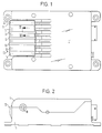
- the roller drive unit comprises a frame 1, 1 'in which a drive roller 10 is rotatably mounted.
- the electric motor for driving the roller is mounted in the housing and connected to the drive roller via a gear train (not shown).
- the drive roller 10 is pivotable about a pivot axis 18, which is eccentric (offset) to the axis of rotation 17, as shown in Fig. 3.
- the drive roller 10 is shown in its lower rest position with solid lines.
- the working position is indicated in Fig. 3 by a broken line. In the working position, the drive roller 10 can then engage the bottom of an object 2 to be conveyed in order to move it in the direction of the arrow C.
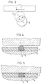
- the drive roller 10 has an outer casing 11 which is divided into a plurality of first, large-area sections 12 and a plurality of second, small-area sections 13.
- the second sections 13 protrude beyond the first sections 12 (seen in the radial direction).
- the drive roller 10 is conically tapered, so that overall a certain crown of the drive roller 10 is produced.
- first friction lining sections 12 are mounted on a (continuous) sleeve 16 and have grooves 15.
- the second, small-area friction lining sections designed as O-rings are fitted in the grooves 15.
- Another advantage of the relatively soft second friction lining sections 13 is that in the event of a sudden engagement between an object 2 to be conveyed (or its leading edge during transport) and the drive roller 10 the resulting impact is mapped and thus the wear of the entire roller drive unit is reduced.
Landscapes
- Engineering & Computer Science (AREA)
- Aviation & Aerospace Engineering (AREA)
- Mechanical Engineering (AREA)
- Rollers For Roller Conveyors For Transfer (AREA)
Applications Claiming Priority (2)
| Application Number | Priority Date | Filing Date | Title |
|---|---|---|---|
| DE4224816 | 1992-07-27 | ||
| DE4224816A DE4224816C1 (fr) | 1992-07-27 | 1992-07-27 |
Publications (1)
| Publication Number | Publication Date |
|---|---|
| EP0581068A1 true EP0581068A1 (fr) | 1994-02-02 |
Family
ID=6464233
Family Applications (1)
| Application Number | Title | Priority Date | Filing Date |
|---|---|---|---|
| EP19930110868 Withdrawn EP0581068A1 (fr) | 1992-07-27 | 1993-07-07 | Unité d'entraînement pour rouleaux |
Country Status (3)
| Country | Link |
|---|---|
| US (1) | US5351808A (fr) |
| EP (1) | EP0581068A1 (fr) |
| DE (1) | DE4224816C1 (fr) |
Cited By (1)
| Publication number | Priority date | Publication date | Assignee | Title |
|---|---|---|---|---|
| DE19854058A1 (de) * | 1998-11-24 | 2000-05-31 | Eduard Leyerer | Förderrolle |
Families Citing this family (5)
| Publication number | Priority date | Publication date | Assignee | Title |
|---|---|---|---|---|
| US5660114A (en) * | 1995-05-10 | 1997-08-26 | Seagate Technology, Inc. | Transport system for thin film sputtering system |
| US5960934A (en) * | 1997-04-11 | 1999-10-05 | Telair International Gmbh | Roller drive unit |
| US20080310944A1 (en) * | 2007-06-14 | 2008-12-18 | Goodrich Corporation | Power drive unit with eccentric roller lift system |
| US7721875B2 (en) * | 2007-06-14 | 2010-05-25 | Goodrich Corporation | Power drive unit with eccentric roller lift system |
| US9403595B1 (en) * | 2015-02-23 | 2016-08-02 | The Boeing Company | Cargo power drive unit with water extraction mechanism |
Citations (2)
| Publication number | Priority date | Publication date | Assignee | Title |
|---|---|---|---|---|
| EP0340009A1 (fr) * | 1988-04-27 | 1989-11-02 | Kornylak Corporation | Transporteur à rouleaux |
| EP0391175A2 (fr) * | 1989-04-06 | 1990-10-10 | Telair International Cargo Systems GmbH | Unité d'entraînement pour rouleau |
Family Cites Families (8)
| Publication number | Priority date | Publication date | Assignee | Title |
|---|---|---|---|---|
| FR1051855A (fr) * | 1951-02-28 | 1954-01-19 | J G Mailander Fa | Rouleau de friction pour le transport de matériaux en bande ou en plaque dans les machines à travailler ces matériaux |
| DE1802544A1 (de) * | 1968-10-11 | 1970-05-27 | Alois Ferch | Treibrolle,insbesondere fuer Blech- und Bandwalzenstrassen |
| US3576250A (en) * | 1969-10-08 | 1971-04-27 | Western Gear Corp | Centrifugally controlled power roller for conveyor system |
| US3899070A (en) * | 1973-06-27 | 1975-08-12 | Boeing Co | Traction-demand power drive unit |
| US4006810A (en) * | 1973-08-01 | 1977-02-08 | Kornylak Corporation | Resilient conveyor rollers |
| FR2549450A1 (fr) * | 1983-07-21 | 1985-01-25 | Electro Pneumatic Int | Unite d'entrainement par rouleaux, notamment pour le deplacement d'objets sur une bande convoyeuse |
| DE3623970A1 (de) * | 1986-07-16 | 1988-01-28 | Leybold Heraeus Gmbh & Co Kg | Transporteinrichtung mit rollensystemen fuer vakuum-beschichtungsanlagen |
| US5205398A (en) * | 1990-07-27 | 1993-04-27 | Eltech Systems Corporation | Insulating roll cover |
-
1992
- 1992-07-27 DE DE4224816A patent/DE4224816C1/de not_active Expired - Fee Related
-
1993
- 1993-07-07 EP EP19930110868 patent/EP0581068A1/fr not_active Withdrawn
- 1993-07-27 US US08/098,472 patent/US5351808A/en not_active Expired - Fee Related
Patent Citations (2)
| Publication number | Priority date | Publication date | Assignee | Title |
|---|---|---|---|---|
| EP0340009A1 (fr) * | 1988-04-27 | 1989-11-02 | Kornylak Corporation | Transporteur à rouleaux |
| EP0391175A2 (fr) * | 1989-04-06 | 1990-10-10 | Telair International Cargo Systems GmbH | Unité d'entraînement pour rouleau |
Cited By (1)
| Publication number | Priority date | Publication date | Assignee | Title |
|---|---|---|---|---|
| DE19854058A1 (de) * | 1998-11-24 | 2000-05-31 | Eduard Leyerer | Förderrolle |
Also Published As
| Publication number | Publication date |
|---|---|
| DE4224816C1 (fr) | 1993-09-02 |
| US5351808A (en) | 1994-10-04 |
Similar Documents
| Publication | Publication Date | Title |
|---|---|---|
| DE2543210C2 (de) | Formschlüssige Verbindung zwischen einer Antriebswelle und einer Wälzlagereinheit | |
| EP0300127B1 (fr) | Unité à galets de propulsion | |
| DE69912556T2 (de) | Reibungsbremse mit zwei Kugelrampenvorrichtungen | |
| DE10112570A1 (de) | Elektrische Scheibenbremse | |
| DE19631592A1 (de) | Elektromechanisch betätigbare Bremse | |
| DE10335193A1 (de) | Selektiv sperrbare Differentialbaugruppe für ein Kraftfahrzeug | |
| EP0440859B1 (fr) | Unité de galets de propulsion | |
| EP0391175A2 (fr) | Unité d'entraînement pour rouleau | |
| DE2913885A1 (de) | Lamellenjalousie mit senkrecht angeordneten lamellen | |
| DE2409149C3 (de) | Schraubengetriebe | |
| DE19715026B4 (de) | Elastischer Antrieb für Druckmaschinen | |
| EP0581068A1 (fr) | Unité d'entraînement pour rouleaux | |
| EP0870702B1 (fr) | Unité d'entraínement pour rouleaux | |
| EP0581069A1 (fr) | Unité d'entraînement pour rouleaux | |
| DE2116175C2 (de) | Nachstellvorrichtung für eine Fahrzeugbremse | |
| DE68908395T2 (de) | Zahnkranzkupplung für mechanische förderer. | |
| DE69116647T2 (de) | Vorrichtung zum Bremsen von Stangen | |
| EP0666431B1 (fr) | Dispositif d'application électromécanique pour freins à friction | |
| DE19536995C2 (de) | Sicherheitsbremse für seilbetriebene Förderanlagen | |
| EP0684412A1 (fr) | Graniture mécanique d'étanchéité | |
| DD244391A5 (de) | Kupplungen | |
| DE3405038A1 (de) | Schaltkupplung | |
| WO2001018426A1 (fr) | Piece d'ecartement pour reducteur de positionnement axial | |
| DE2540348A1 (de) | Reibungsarme hubmutter mit selbsthemmung | |
| EP0205927B1 (fr) | Réajustage automatique pour la timonerie de frein, en particulier de véhicules ferroviaires |
Legal Events
| Date | Code | Title | Description |
|---|---|---|---|
| PUAI | Public reference made under article 153(3) epc to a published international application that has entered the european phase |
Free format text: ORIGINAL CODE: 0009012 |
|
| AK | Designated contracting states |
Kind code of ref document: A1 Designated state(s): DE FR GB IT |
|
| RAP3 | Party data changed (applicant data changed or rights of an application transferred) |
Owner name: TELAIR INTERNATIONAL CARGO SYSTEMS GMBH |
|
| STAA | Information on the status of an ep patent application or granted ep patent |
Free format text: STATUS: THE APPLICATION IS DEEMED TO BE WITHDRAWN |
|
| 18D | Application deemed to be withdrawn |
Effective date: 19940803 |