EP0580592B1 - Appareil medical pour l'administration de fluides avec compensation des variations de pression - Google Patents
Appareil medical pour l'administration de fluides avec compensation des variations de pression Download PDFInfo
- Publication number
- EP0580592B1 EP0580592B1 EP92905132A EP92905132A EP0580592B1 EP 0580592 B1 EP0580592 B1 EP 0580592B1 EP 92905132 A EP92905132 A EP 92905132A EP 92905132 A EP92905132 A EP 92905132A EP 0580592 B1 EP0580592 B1 EP 0580592B1
- Authority
- EP
- European Patent Office
- Prior art keywords
- pressure
- fluid
- column
- tube
- patient
- Prior art date
- Legal status (The legal status is an assumption and is not a legal conclusion. Google has not performed a legal analysis and makes no representation as to the accuracy of the status listed.)
- Expired - Lifetime
Links
Images

Classifications
-
- A—HUMAN NECESSITIES
- A61—MEDICAL OR VETERINARY SCIENCE; HYGIENE
- A61B—DIAGNOSIS; SURGERY; IDENTIFICATION
- A61B5/00—Measuring for diagnostic purposes; Identification of persons
- A61B5/02—Detecting, measuring or recording pulse, heart rate, blood pressure or blood flow; Combined pulse/heart-rate/blood pressure determination; Evaluating a cardiovascular condition not otherwise provided for, e.g. using combinations of techniques provided for in this group with electrocardiography or electroauscultation; Heart catheters for measuring blood pressure
- A61B5/021—Measuring pressure in heart or blood vessels
- A61B5/0215—Measuring pressure in heart or blood vessels by means inserted into the body
-
- A—HUMAN NECESSITIES
- A61—MEDICAL OR VETERINARY SCIENCE; HYGIENE
- A61M—DEVICES FOR INTRODUCING MEDIA INTO, OR ONTO, THE BODY; DEVICES FOR TRANSDUCING BODY MEDIA OR FOR TAKING MEDIA FROM THE BODY; DEVICES FOR PRODUCING OR ENDING SLEEP OR STUPOR
- A61M5/00—Devices for bringing media into the body in a subcutaneous, intra-vascular or intramuscular way; Accessories therefor, e.g. filling or cleaning devices, arm-rests
- A61M5/14—Infusion devices, e.g. infusing by gravity; Blood infusion; Accessories therefor
- A61M5/168—Means for controlling media flow to the body or for metering media to the body, e.g. drip meters, counters ; Monitoring media flow to the body
- A61M5/16831—Monitoring, detecting, signalling or eliminating infusion flow anomalies
- A61M5/16854—Monitoring, detecting, signalling or eliminating infusion flow anomalies by monitoring line pressure
Definitions
- This invention relates to pressure monitoring systems and, more particularly, to such systems which include means for normalizing unwanted pressure variations due to instrumentation movement.
- a typical flush system includes a pressurized bag in which the pressure is maintained at approximately 300 mm Hg or 400 cms of water.
- the purpose of the bag is to provide a source of fluid to flush the line to the patient, either to fill the line with fluid or to flush blood back to the patient after blood fills the system during blood withdrawal. It is also used as a sorce of continuous flush to keep blood from forming clots over the end of an indwelling catheter connecting the tubing to the patients vascular system.
- the pressure in the bag must be greater than the patients blood pressure (about 100 mm Hg.) so that it can overcome the back pressure during intermittent flush. Continuous flush occurs via a restrictor mechanism as is well known.
- the system is in series with the pressurized bag and the downstream components of the system.
- the system consists of a restrictor designed to allow about 3 cc/hour of fluid to flow across an upstream-downstream pressure gradient of 0,26664 bar (200 mm Hg, i.e. 300 minus the back pressure of a nominal 100).
- a restrictor this tight adds nearly no additional pressure to tile system, and what little it does produce is a continuous bias accounted for during the process of zeroing the system as described more fully hereinafter.
- the intermittent flush is simply a bypass valve that allows the fullupstream pressure to bypass the restrictor and produce a rapid flush of the system.
- valves consist of a mechanism which, when pressed or squeezed, allows a valving mechanism to open.
- the fail-sale condition of the valve is a no-pass condition, a safety feature necessary to protect the downstream environment (patient) from potentialy harmfull pressures and flows.
- Such a system also includes a transducer.
- the transducer is traditionally a gage type of pressure sensing device, meaning that it senses system pressure and uses atmospheric pressure as it's reference. This type of transducer has been used because it requires only one surface of the transducer to be exposed to the system environment. The other side of the transducer, in addition to being exposed to atmospheric pressure, interfaces with the electronic and mechanical components of the transducer. Because of the technical nature of the transducer, little emphasis has been placed on true differential sensing. Instead, there has developed a nearly universal acceptance of the use of unchanging atmospheric pressure as a default.
- the transducer may be placed upstream or downstream from the flush device. If it is downstream, the transducer chamber has two ports. Fluid enters one port as it travels from the flush device to the transducer. It then travels through the transducer, purging it of air, and exits the second port, toward the patient. If the transducer is located upstream from the flush device, it is "dead ended” on one arm of a "T" arrangement, with the fluid from the reservoir bag entering the stem of the "T" and then either passing upstream to the transducer or downstream to the patient. The second port of the transducer is then opened only to allow air to purge the system during priming. Then it is closed.
- stopcocks which serve the function of either isolating regions or of venting ports when appropriate.
- the configuration of the system is such that a first column of tubing extends from the transducer (or flush device) to the patient. As a result, there is a continuous column of fluid extending from the transducer to the patient's vascular system and from there to his heart.
- the reservoir bag is pressurized to 0,39996 bar (300 mm Hg), a nominal setting. While the system is set for this pressure, it's function is not guaranteed even if the pressure is maintained at a constant level. This is so because the flush system is most dependent on the setting as it depends on the upstream pressure to provide the driving force necessary to maintain the 3 cc/hour flow through the restrictor, assuming the downstream pressure to be a mean of 0,13332 bar (100 mm Hg).
- the transducer for such a system is available in a variety of types. Specifically, pressure is sensed either by electrical or mechanical means. Electrical transducers also are of a variety of types including strain gages, silcon chip, conductance, inductance, reluctance, ---etc. Mechanical types include diaphragm-needle gages, fluid columns, Mercury manometers,--etc.
- the transducer is always "differential" in that it measures the target pressure relative to a second pressure. If the second pressure is atmospheric pressure, it is termed a "gage". If the second pressure is a vacuum, it is an absolute pressure. If the second pressure is a pressure within a controlled chamber, the transducer is called "differential".
- the transducer may or may not be able to measure the pressure of liquids as well as gases or it may be able to accept liquids on only one side of it's pressure sensitive member, allowing only gas on the other side of the member. It is therefor either dry/dry, wet/dry or wet/wet.
- the tranducer has to be calibrated to establish a reference or "zero" value.
- Zeroing a fluid filled transducer traditionally means isolating the chamber on the sensing side of the transducer and filling the chamber with fluid (if the system is to measure fluid pressure) and often opening the transducer to atmospheric pressure. The electrical or mechanical signal produced by the pressure sensing member under these conditions is taken as "zero".
- the system has nulled all the factors except the ones desired to be measured, and reads the pressure relative to atmospheric pressure.
- the system to be measured is distant from the transducer, and contains fluid, there must be a continuous fluid path or pipe connecting to the system to be measured. Since the fluid has a density greater than air, which is the reference medium generating the reference pressure, the vertical height of the fluid column between the transducer and the site of measurement must be considered.
- the pressure measurement at the transducer is the pressure at the site of importance plus or minus the pressure generated by the fluid column that exists between the transducer and the site of measurement.
- the blood pressure that is taken as standard is the pressure at the central aorta at the point of exit from the heart.
- Venous pressure is taken as Central Venous Pressure (CVP), which is the pressure that exists in the right Atrium of the heart.
- CVP Central Venous Pressure
- Other physiological pressures are often taken at specific locations within the body, eg. the brain, the pulmanary artery, the chest, the esophagus, the stomach, etc.
- a pressure sensor is connected so that any change in the vertical position of a patient relative to that of the sensor is normalized so that the instrumentation does not register a change in pressure when a change in vertical position occurs.
- the normalization is produced by exposing the backside surface of the sensor to a second column of fluid.
- One end of the second column is controllably connected to the first column on the patient side of the sensor (down stream).
- the other end of the second column is exposed to atmospheric pressure and is connected, illustratively, to the patients chest wall.
- the first column is the vertical height from the patient's side of the transducer to the insertion point in the vessel and then to the origin of the fluid, i. e., the aortic valve of the heart.
- the heights of the two columns are always equal to one another and any change in the vertical position of a patient with respect to that of the sensor appears as an equal change in the height of the fluid in both columns.
- the monitoring system does not indicate any false blood pressure readings due to a change in vertical position.
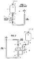
- FIG. 1 shows a prior art pressure monitoring system 10 for patient end use.
- the system includes a fluid container 11 which is a reservoir for fluid.
- the fluid container normally is sealed and pressurized to 0,39996 bar (300 mm of Mercury or 420 CMS of water).
- the system also includes a tube 12 which extends from the reservoir and terminates at it's distal end in a hypodermic needle for connection to the vascular system of a patient.
- the tube includes several stop cocks 13 and 14 for interupting fluid flow and at least one fluid control valve 16 for regulating fluid flow in the system.
- the system also includes a pressure sensor 20 one surface 21 of which is exposed to the fluid. The second surface 22 of the sensor is exposed to air as shown.
- the pressure sensor is connected to an electronic display 25.
- Display 25 is calibrated with respect to a reference pressure by flushing the system with fluid and by measuring the pressure of the fluid.
- the backside surface, 22, of the sensor is at atmospheric pressure and so the reference pressure turns out to be the reference pressure under the conditions specified.
- the reference pressure is the pressure at the vertical distance of the patient's heart with respect to the sensor. If that vertical distance,measured, say, at broken horizontal line 27,later changes, the calibration is no longer valid and false readings result. Frequent changes in the patients position do occur and such changes do lead to frequent changes in the blood pressure readings. This, in turn, leads to a requirement of frequent monitoring and retraining by trained health care specialists.
- Figure 2 shows a pressure monitoring system in accordance with the principles of this invention.
- the system includes an additional tube communicating with the backside surface (22) of the sensor.
- the tube is filled partially with fluid and is maintained at atmospheric pressure.
- the fluid in the tube is operative to normalize any change in pressure in the system due to a change in the relative heights of the patient and the sensor.
- figure, 2 shows a pressure monitoring system 40.
- the system includes a fluid container or bag 41 analogous to bag 11 of figure 1.
- the bag again is hung from a stand (not shown) by hook 42 engaging a hole 43 in extension 44 at the top of the bag.
- a tube 46 exits the bag at the bottom, as viewed, and communicates, via a stop cock and restrictor assembly 48, with pressure sensor 49.
- Pressure sensor 49 separates two chambers 50 and 51.
- Tube 46 communicates with chamber 50.
- a second tube 53 communicates with chamber 51 via stop cock assembly 54.
- Chambers 50 and 51 are connected to a tube 55 via stop cock assembly 60.
- tube 53 is partially filled with fluid and both surfaces of the sensor are exposed to fluid. In the embodiment of figure 2, tube 53 is open to air.
- stop cock assembly 60 In normal operation, the system is first flushed by closing stop cock assembly 60 to the patient, thus interrupting the fluid path and opening the path from path 46 to path 53.
- stop cock assembly 60 is a three or four way stop cock connecting path 46 to path 55 to the patient, connecting paths 46 and 53 to one another, and closing off or opening all paths.
- the system next is changed by the adjustment of stop cock assembly 60 to connect path 46 to path 53 and closing off path 55.
- the system is now flushed out to remove air.
- Pressure P2 in path 46 is now isolated. It is to be understood that the P1 side (path 53) contains fluid and, in the embodiments of figure 2, that fluid is contained in a tube which is open to air.
- Figure 3 shows an embodiment where the second column is not open to air, but is separated from air by a diaphragm which is permeable to air but not to the fluid contents of the path.
- figure 3 shows a tube 72 which corresponds to tube 53 of figure 2. Tube 72 terminates at the top, as viewed, in a reservoir 73 which is open at 75.
- a diaphragm or partition 76 separates the fluid contents, indicated at 77, from air.
- the diaphragm is aerophilic comprising illustratively Teflon which pass air but not the fluid contents.
- a drain tube 78 having a diameter smaller than that of the inlet tube, as shown, terminates in a reservoir 79.
- Figure 4 shows an embodiment 80 corresponding to the embodiment of figure 2 where path 81 corresponds to path 53 of figure 2.
- the tube defining path 53 is in the form of an upside down U with an opening to air at the "top" of the U as shown at 83, in one embodiment, or including a aerophilic diaphragm, shown dotted at 84, in a separate embodiment.
- Figure 4 also shows a plurality of stop cocks 87, 88, and 89 corresponding to stop cocks 48, 54, and 60 of figure 2. Drain tube 90 terminates in an open bag not shown.
- the proximal end of the pressure compensating tube may be attached to the chest wall of a patient, illustratively, by means of a suction cup nipple frequently used for EKG readings and by clamping the proximal end of the tube to the nipple.
- Any vertical movement of the patient relative to the fluid reservoir results in a change in the height 92 of the fluid level in path 81.
- the main cause of change in blood pressure readings is avoided resulting in a significant reduction in the demand for attention by health care specialists, a concommitant reduction in associated costs and a safer response by such specialists.
- FIG. 2 The embodiments of figures 2, 3, and 4 utilize a wet/wet sensor. Such a sensor is available from Motorola.
Claims (11)
- Système de détection de pression (40) pour les soins à un patient pour surveiller la pression dans une première colonne de liquide qui est fermée et sous pression, dans lequel ledit système comporte un dispositif de détection de pression (49), le système étant
caractérisé en ce que le dispositif de détection de pression (49) possède des première et seconde surfaces principales, ladite première surface communiquant avec le fluide dans ladite première colonne, que ledit système comporte une seconde colonne de fluide, ladite seconde surface communiquant avec ladite seconde colonne, et présente des moyens pour maintenir les hauteurs desdites première et seconde colonnes égales l'une à l'autre. - Système de détection de pression tel que défini dans la revendication 1 comportant également des moyens électroniques d'affichage (25), ledit détecteur (49) étant raccordé auxdits moyens d'affichage (25) pour fournir une indication de la pression de fluide dans ladite première colonne.
- Système de détection de pression tel que défini dans la revendication 2 dans lequel ladite première colonne est raccordée entre ledit détecteur (49) et un patient pour mesurer des pression physiologiques.
- Système de surveillance de pression de la revendication 1, ledit système comprenant une première colonne de fluide pour fournir des fluides audit patient, ladite colonne de fluide étant raccordée audit détecteur de pression (49) à une extrémité proximale de celle-ci et étant appropriée à ladite extrémité distale pour s'accoupler à une aiguille pour la liaison à un patient, ladite seconde colonne contenant aussi du fluide et communiquant avec ladite première colonne, ladite seconde colonne comportant également des moyens pour y maintenir la pression atmosphérique pour ramener à la normale toutes variations de pression dans ladite première colonne.
- Système de détection de pression tel que défini dans la revendication 4, ledit système comportant également des moyens de régulation pour commander l'écoulement de fluide dans lesdites première et seconde colonnes respectivement, ledit système comportant également des moyens de vanne (60) pour interrompre l'écoulement de liquide vers un patient et pour permettre la communication de fluide de l'une desdites première et seconde voies ou à la fois desdites première et seconde voies vers ledit patient sélectivement.
- Système tel que défini dans la revendication 5 dans lequel ladite seconde colonne est ouverte à l'air à une première extrémité.
- Système tel que défini dans la revendication 5 dans lequel ladite seconde colonne comporte une cloison (84) à une première extrémité de celle-ci, ladite cloison étant d'une matière laissant passer l'air mais non ledit fluide.
- Système tel que défini dans la revendication 7 dans lequel ladite cloison (83) comprend une matière aérophile.
- Système de surveillance de pression de la revendication 1 pour surveiller la pression de fluide dans un tube raccordé entre une source pressurisée et un patient, ledit système comprenant ladite source de fluide (41), un tube raccordé à ladite source de fluide (41) à son extrémité proximale et à une aiguille à son extrémité distale pour un raccordement intervasculaire audit patient, ledit tube comportant des premiers moyens de vanne (60) pour interrompre l'écoulement de fluide dans ledit tube, ledit système comportant également un second tube, ledit second tube comportant des seconds moyens de vanne (54) pour interrompre l'écoulement de fluide dans ledit second tube, ledit second tube comportant également des moyens à son extrémité distale pour maintenir du fluide dans ledit second tube à la pression atmosphérique et des moyens de commande à son extrémité proximale pour raccorder ensemble de manière commandée ladite seconde voie à ladite première voie, ledit système comportant des moyens de détection de pression (49) présentant des première et seconde surfaces exposées au fluide dans les premier et second tubes respectivement.
- Système tel que défini dans la revendication 9 dans lequel lesdits moyens pour maintenir ledit second tube à la pression atmosphérique comprennent une ouverture à l'air (83) dans l'extrémité distale dudit second tube.
- Système tel que défini dans la revendication 10 dans lequel lesdits moyens pour maintenir ledit second tube à la pression atmosphérique comprennent une cloison (84) qui laisse passer l'air mais non ledit fluide.
Applications Claiming Priority (3)
| Application Number | Priority Date | Filing Date | Title |
|---|---|---|---|
| US07/644,895 US5098384A (en) | 1991-01-23 | 1991-01-23 | Pressure-compensated fluid administering apparatus |
| US644895 | 1991-01-23 | ||
| PCT/US1992/000439 WO1992012742A1 (fr) | 1991-01-23 | 1992-01-17 | Appareil medical pour l'administration de fluides avec compensation des variations de pression |
Publications (3)
| Publication Number | Publication Date |
|---|---|
| EP0580592A1 EP0580592A1 (fr) | 1994-02-02 |
| EP0580592A4 EP0580592A4 (fr) | 1994-03-24 |
| EP0580592B1 true EP0580592B1 (fr) | 1998-08-05 |
Family
ID=24586788
Family Applications (1)
| Application Number | Title | Priority Date | Filing Date |
|---|---|---|---|
| EP92905132A Expired - Lifetime EP0580592B1 (fr) | 1991-01-23 | 1992-01-17 | Appareil medical pour l'administration de fluides avec compensation des variations de pression |
Country Status (6)
| Country | Link |
|---|---|
| US (1) | US5098384A (fr) |
| EP (1) | EP0580592B1 (fr) |
| AU (1) | AU1267792A (fr) |
| DE (1) | DE69226523T2 (fr) |
| IL (1) | IL100748A0 (fr) |
| WO (1) | WO1992012742A1 (fr) |
Families Citing this family (42)
| Publication number | Priority date | Publication date | Assignee | Title |
|---|---|---|---|---|
| EP0692265B1 (fr) * | 1991-08-21 | 2000-05-24 | Smith & Nephew, Inc. | Système de contrôle de fluides |
| US5514102A (en) * | 1995-05-05 | 1996-05-07 | Zevex Incorporated | Pressure monitoring enteral feeding system and method |
| US5691478A (en) * | 1995-06-07 | 1997-11-25 | Schneider/Namic | Device and method for remote zeroing of a biological fluid pressure measurement device |
| US6371937B1 (en) * | 2000-03-27 | 2002-04-16 | I-Flow Corporation | Manometer infusion apparatus |
| US6616597B2 (en) * | 2000-12-12 | 2003-09-09 | Datascope Investment Corp. | Intra-aortic balloon catheter having a dual sensor pressure sensing system |
| US6691579B2 (en) * | 2001-05-07 | 2004-02-17 | Respironics, Inc. | Portable pressure transducer, pneumotach for use therewith, and associated methods |
| US8182461B2 (en) * | 2003-11-04 | 2012-05-22 | Smiths Medical Asd, Inc. | Syringe pump rapid occlusion detection system |
| US6993954B1 (en) * | 2004-07-27 | 2006-02-07 | Tekscan, Incorporated | Sensor equilibration and calibration system and method |
| EP1778079A2 (fr) * | 2004-08-12 | 2007-05-02 | Edwards Lifesciences Corporation | Systeme et procede de calibrage pour surveiller une pression |
| US7775966B2 (en) | 2005-02-24 | 2010-08-17 | Ethicon Endo-Surgery, Inc. | Non-invasive pressure measurement in a fluid adjustable restrictive device |
| US8016744B2 (en) | 2005-02-24 | 2011-09-13 | Ethicon Endo-Surgery, Inc. | External pressure-based gastric band adjustment system and method |
| US7775215B2 (en) | 2005-02-24 | 2010-08-17 | Ethicon Endo-Surgery, Inc. | System and method for determining implanted device positioning and obtaining pressure data |
| US7699770B2 (en) | 2005-02-24 | 2010-04-20 | Ethicon Endo-Surgery, Inc. | Device for non-invasive measurement of fluid pressure in an adjustable restriction device |
| US8066629B2 (en) | 2005-02-24 | 2011-11-29 | Ethicon Endo-Surgery, Inc. | Apparatus for adjustment and sensing of gastric band pressure |
| US7658196B2 (en) | 2005-02-24 | 2010-02-09 | Ethicon Endo-Surgery, Inc. | System and method for determining implanted device orientation |
| US7927270B2 (en) | 2005-02-24 | 2011-04-19 | Ethicon Endo-Surgery, Inc. | External mechanical pressure sensor for gastric band pressure measurements |
| US8870742B2 (en) | 2006-04-06 | 2014-10-28 | Ethicon Endo-Surgery, Inc. | GUI for an implantable restriction device and a data logger |
| US8152710B2 (en) | 2006-04-06 | 2012-04-10 | Ethicon Endo-Surgery, Inc. | Physiological parameter analysis for an implantable restriction device and a data logger |
| US8187163B2 (en) | 2007-12-10 | 2012-05-29 | Ethicon Endo-Surgery, Inc. | Methods for implanting a gastric restriction device |
| US8100870B2 (en) | 2007-12-14 | 2012-01-24 | Ethicon Endo-Surgery, Inc. | Adjustable height gastric restriction devices and methods |
| US8377079B2 (en) | 2007-12-27 | 2013-02-19 | Ethicon Endo-Surgery, Inc. | Constant force mechanisms for regulating restriction devices |
| US8142452B2 (en) | 2007-12-27 | 2012-03-27 | Ethicon Endo-Surgery, Inc. | Controlling pressure in adjustable restriction devices |
| US8591395B2 (en) | 2008-01-28 | 2013-11-26 | Ethicon Endo-Surgery, Inc. | Gastric restriction device data handling devices and methods |
| US8337389B2 (en) | 2008-01-28 | 2012-12-25 | Ethicon Endo-Surgery, Inc. | Methods and devices for diagnosing performance of a gastric restriction system |
| US8192350B2 (en) | 2008-01-28 | 2012-06-05 | Ethicon Endo-Surgery, Inc. | Methods and devices for measuring impedance in a gastric restriction system |
| US8221439B2 (en) | 2008-02-07 | 2012-07-17 | Ethicon Endo-Surgery, Inc. | Powering implantable restriction systems using kinetic motion |
| US7844342B2 (en) | 2008-02-07 | 2010-11-30 | Ethicon Endo-Surgery, Inc. | Powering implantable restriction systems using light |
| US8114345B2 (en) | 2008-02-08 | 2012-02-14 | Ethicon Endo-Surgery, Inc. | System and method of sterilizing an implantable medical device |
| US8591532B2 (en) | 2008-02-12 | 2013-11-26 | Ethicon Endo-Sugery, Inc. | Automatically adjusting band system |
| US8057492B2 (en) | 2008-02-12 | 2011-11-15 | Ethicon Endo-Surgery, Inc. | Automatically adjusting band system with MEMS pump |
| US8034065B2 (en) | 2008-02-26 | 2011-10-11 | Ethicon Endo-Surgery, Inc. | Controlling pressure in adjustable restriction devices |
| US8187162B2 (en) | 2008-03-06 | 2012-05-29 | Ethicon Endo-Surgery, Inc. | Reorientation port |
| US8233995B2 (en) | 2008-03-06 | 2012-07-31 | Ethicon Endo-Surgery, Inc. | System and method of aligning an implantable antenna |
| US8486020B2 (en) | 2010-08-11 | 2013-07-16 | Zevex, Inc. | Pressure sensor and method of use |
| AU2011308700B2 (en) | 2010-10-01 | 2015-04-02 | Zevex, Inc. | Pressure sensor seal and method of use |
| JP2013538650A (ja) | 2010-10-01 | 2013-10-17 | ゼヴェクス・インコーポレーテッド | 輸液ポンプのための圧力監視システム |
| JP2014527412A (ja) | 2011-03-29 | 2014-10-16 | エアウェイ メディックス スポルカ ゼット.オ.オ.Airway Medix Spolka Z.O.O. | バルーン型換気チューブクリーニング装置 |
| US10500360B1 (en) | 2014-08-29 | 2019-12-10 | Teleflex Life Sciences Unlimited Company | Catheter for cleaning of tracheal ventilation tubes |
| JP6475958B2 (ja) | 2014-11-27 | 2019-02-27 | 日東電工株式会社 | 投薬機構及び投薬機構用ポンプユニット |
| CN109152870A (zh) * | 2016-03-09 | 2019-01-04 | 艾尔维麦迪克斯股份有限公司 | 导管充气袖带压力稳定器 |
| US10092719B1 (en) | 2017-09-13 | 2018-10-09 | Airway Medix S.A. | Catheter inflatable cuff pressure stabilizer |
| US10286170B1 (en) | 2018-02-20 | 2019-05-14 | Airway Medix S.A. | Catheter inflatable cuff pressure stabilizer |
Family Cites Families (12)
| Publication number | Priority date | Publication date | Assignee | Title |
|---|---|---|---|---|
| US3124133A (en) * | 1964-03-10 | Infusion apparatus | ||
| US2105127A (en) * | 1936-02-05 | 1938-01-11 | Mathieson Alkali Works Inc | Fluid meter |
| US2600324A (en) * | 1949-08-25 | 1952-06-10 | Sanborn Company | Fluid pressure measuring apparatus |
| US2615940A (en) * | 1949-10-25 | 1952-10-28 | Williams Milton | Electrokinetic transducing method and apparatus |
| US3242920A (en) * | 1963-06-07 | 1966-03-29 | Andersen Prod H W | Manometer and method of using same |
| DE1566140B1 (de) * | 1967-07-22 | 1970-03-26 | Pfrimmer & Co J | Vorrichtung zur Einstellung des Skalennullpunktes von Venendruckmessgeraeten |
| DE1810802A1 (de) * | 1968-11-25 | 1970-06-04 | Dr Med Gerhard Metz | Dosiervorrichtungen fuer Infusionen |
| US3611811A (en) * | 1970-03-27 | 1971-10-12 | Liquidonics Inc | Differential density manometer |
| EP0133583A1 (fr) * | 1983-08-12 | 1985-02-27 | Sterimed Gesellschaft für medizinischen Bedarf mbH | Appareil d'infusion muni d'un dispositif de détermination de la pression veineuse centrale |
| US4902277A (en) * | 1987-08-26 | 1990-02-20 | Orthoconcept | Circulating a liquid through a joint |
| US4820265A (en) * | 1986-12-16 | 1989-04-11 | Minnesota Mining And Manufacturing Company | Tubing set |
| US4769001A (en) * | 1987-02-25 | 1988-09-06 | Baxter International Inc. | Method and apparatus for calibrating plural pump fluid flow system |
-
1991
- 1991-01-23 US US07/644,895 patent/US5098384A/en not_active Expired - Lifetime
-
1992
- 1992-01-17 AU AU12677/92A patent/AU1267792A/en not_active Abandoned
- 1992-01-17 EP EP92905132A patent/EP0580592B1/fr not_active Expired - Lifetime
- 1992-01-17 WO PCT/US1992/000439 patent/WO1992012742A1/fr active IP Right Grant
- 1992-01-17 DE DE69226523T patent/DE69226523T2/de not_active Expired - Fee Related
- 1992-01-23 IL IL100748A patent/IL100748A0/xx unknown
Also Published As
| Publication number | Publication date |
|---|---|
| AU1267792A (en) | 1992-08-27 |
| DE69226523D1 (de) | 1998-09-10 |
| WO1992012742A1 (fr) | 1992-08-06 |
| DE69226523T2 (de) | 1998-12-10 |
| US5098384A (en) | 1992-03-24 |
| EP0580592A1 (fr) | 1994-02-02 |
| EP0580592A4 (fr) | 1994-03-24 |
| IL100748A0 (en) | 1992-09-06 |
Similar Documents
| Publication | Publication Date | Title |
|---|---|---|
| EP0580592B1 (fr) | Appareil medical pour l'administration de fluides avec compensation des variations de pression | |
| EP0475686B1 (fr) | Dispositif et procédé destiné au recalibrage à zéro d'un capteur de pression in vivo | |
| US5795307A (en) | Shunt tap apparatus and method | |
| US6120457A (en) | In vivo zeroing of catheter pressure sensor | |
| JP2832461B2 (ja) | プレッシャメータカテーテル | |
| US4779626A (en) | Method and apparatus for compensating for transducer position in blood pressure monitoring system | |
| JP5062727B2 (ja) | 患者の血圧測定を行うための血管カテーテルと流体移送システム | |
| US4342218A (en) | Method and apparatus for zeroing and calibrating an invasive blood pressure monitoring system | |
| US3713341A (en) | Pressure transducer | |
| US4610256A (en) | Pressure transducer | |
| US6162182A (en) | Pressure tip cannula | |
| US4621647A (en) | Intracranial pressure regulating system | |
| US4621646A (en) | Blood flow measuring method | |
| US4858619A (en) | Intracranial pressure monitoring system | |
| US4648406A (en) | Physiological pressure measuring system | |
| JP2736195B2 (ja) | カテーテルアダプタのためのコネクタ | |
| US4613325A (en) | Flow rate sensing device | |
| US7722557B2 (en) | Blood purification apparatus | |
| WO1989010089A1 (fr) | Dispositif a un seul capteur pour la detection d'un differentiel de pression | |
| JP2014517753A (ja) | フロー検出器を有する輸液器具 | |
| US5691478A (en) | Device and method for remote zeroing of a biological fluid pressure measurement device | |
| US5203340A (en) | Apparatus for rezeroing an in vivo pressure sensor and method for rezeroing | |
| EP1294417B1 (fr) | Manometre pour appareil de perfusion | |
| US4562845A (en) | Methods and apparatus for testing a blood pressure monitoring system of the hydraulic type | |
| US5063936A (en) | Internal pressure measuring device using catheter with multiple lumens |
Legal Events
| Date | Code | Title | Description |
|---|---|---|---|
| PUAI | Public reference made under article 153(3) epc to a published international application that has entered the european phase |
Free format text: ORIGINAL CODE: 0009012 |
|
| 17P | Request for examination filed |
Effective date: 19931027 |
|
| AK | Designated contracting states |
Kind code of ref document: A1 Designated state(s): DE FR GB |
|
| 17Q | First examination report despatched |
Effective date: 19951102 |
|
| GRAG | Despatch of communication of intention to grant |
Free format text: ORIGINAL CODE: EPIDOS AGRA |
|
| GRAG | Despatch of communication of intention to grant |
Free format text: ORIGINAL CODE: EPIDOS AGRA |
|
| GRAG | Despatch of communication of intention to grant |
Free format text: ORIGINAL CODE: EPIDOS AGRA |
|
| GRAH | Despatch of communication of intention to grant a patent |
Free format text: ORIGINAL CODE: EPIDOS IGRA |
|
| GRAH | Despatch of communication of intention to grant a patent |
Free format text: ORIGINAL CODE: EPIDOS IGRA |
|
| GRAA | (expected) grant |
Free format text: ORIGINAL CODE: 0009210 |
|
| AK | Designated contracting states |
Kind code of ref document: B1 Designated state(s): DE FR GB |
|
| REF | Corresponds to: |
Ref document number: 69226523 Country of ref document: DE Date of ref document: 19980910 |
|
| ET | Fr: translation filed | ||
| PLBE | No opposition filed within time limit |
Free format text: ORIGINAL CODE: 0009261 |
|
| STAA | Information on the status of an ep patent application or granted ep patent |
Free format text: STATUS: NO OPPOSITION FILED WITHIN TIME LIMIT |
|
| 26N | No opposition filed | ||
| REG | Reference to a national code |
Ref country code: GB Ref legal event code: IF02 |
|
| PGFP | Annual fee paid to national office [announced via postgrant information from national office to epo] |
Ref country code: DE Payment date: 20080731 Year of fee payment: 17 |
|
| PGFP | Annual fee paid to national office [announced via postgrant information from national office to epo] |
Ref country code: FR Payment date: 20080731 Year of fee payment: 17 |
|
| PGFP | Annual fee paid to national office [announced via postgrant information from national office to epo] |
Ref country code: GB Payment date: 20080731 Year of fee payment: 17 |
|
| GBPC | Gb: european patent ceased through non-payment of renewal fee |
Effective date: 20090117 |
|
| PG25 | Lapsed in a contracting state [announced via postgrant information from national office to epo] |
Ref country code: DE Free format text: LAPSE BECAUSE OF NON-PAYMENT OF DUE FEES Effective date: 20090801 |
|
| REG | Reference to a national code |
Ref country code: FR Ref legal event code: ST Effective date: 20091030 |
|
| PG25 | Lapsed in a contracting state [announced via postgrant information from national office to epo] |
Ref country code: GB Free format text: LAPSE BECAUSE OF NON-PAYMENT OF DUE FEES Effective date: 20090117 |
|
| PG25 | Lapsed in a contracting state [announced via postgrant information from national office to epo] |
Ref country code: FR Free format text: LAPSE BECAUSE OF NON-PAYMENT OF DUE FEES Effective date: 20090202 |