EP0580098A1 - Method and device for pile foundation - Google Patents
Method and device for pile foundation Download PDFInfo
- Publication number
- EP0580098A1 EP0580098A1 EP93111516A EP93111516A EP0580098A1 EP 0580098 A1 EP0580098 A1 EP 0580098A1 EP 93111516 A EP93111516 A EP 93111516A EP 93111516 A EP93111516 A EP 93111516A EP 0580098 A1 EP0580098 A1 EP 0580098A1
- Authority
- EP
- European Patent Office
- Prior art keywords
- press
- segments
- piles
- pile
- pressed
- Prior art date
- Legal status (The legal status is an assumption and is not a legal conclusion. Google has not performed a legal analysis and makes no representation as to the accuracy of the status listed.)
- Withdrawn
Links
- 238000000034 method Methods 0.000 title claims abstract description 35
- 230000002787 reinforcement Effects 0.000 claims description 15
- 238000003825 pressing Methods 0.000 claims description 11
- 229910000831 Steel Inorganic materials 0.000 claims description 8
- 239000010959 steel Substances 0.000 claims description 8
- 239000000463 material Substances 0.000 claims 3
- 238000004382 potting Methods 0.000 claims 3
- 230000001105 regulatory effect Effects 0.000 claims 1
- 239000011150 reinforced concrete Substances 0.000 claims 1
- XLYOFNOQVPJJNP-UHFFFAOYSA-N water Substances O XLYOFNOQVPJJNP-UHFFFAOYSA-N 0.000 description 8
- 230000008859 change Effects 0.000 description 5
- 238000006243 chemical reaction Methods 0.000 description 3
- 238000003780 insertion Methods 0.000 description 3
- 230000037431 insertion Effects 0.000 description 3
- 239000003415 peat Substances 0.000 description 3
- 230000008569 process Effects 0.000 description 3
- 239000002689 soil Substances 0.000 description 3
- 229910001294 Reinforcing steel Inorganic materials 0.000 description 2
- 238000011161 development Methods 0.000 description 2
- 230000018109 developmental process Effects 0.000 description 2
- 238000005553 drilling Methods 0.000 description 2
- 238000009415 formwork Methods 0.000 description 2
- 239000011435 rock Substances 0.000 description 2
- 239000004576 sand Substances 0.000 description 2
- 241000894006 Bacteria Species 0.000 description 1
- 230000006978 adaptation Effects 0.000 description 1
- 238000004873 anchoring Methods 0.000 description 1
- 230000004888 barrier function Effects 0.000 description 1
- 238000009412 basement excavation Methods 0.000 description 1
- 230000008901 benefit Effects 0.000 description 1
- 230000005540 biological transmission Effects 0.000 description 1
- 238000010276 construction Methods 0.000 description 1
- 238000000354 decomposition reaction Methods 0.000 description 1
- 230000007547 defect Effects 0.000 description 1
- 230000001419 dependent effect Effects 0.000 description 1
- 239000003651 drinking water Substances 0.000 description 1
- 235000020188 drinking water Nutrition 0.000 description 1
- 230000009977 dual effect Effects 0.000 description 1
- 230000000694 effects Effects 0.000 description 1
- 239000003673 groundwater Substances 0.000 description 1
- 238000007373 indentation Methods 0.000 description 1
- 239000007924 injection Substances 0.000 description 1
- 238000002347 injection Methods 0.000 description 1
- 230000007774 longterm Effects 0.000 description 1
- 230000000149 penetrating effect Effects 0.000 description 1
- 239000011148 porous material Substances 0.000 description 1
- 238000009418 renovation Methods 0.000 description 1
- 239000007787 solid Substances 0.000 description 1
- 230000003068 static effect Effects 0.000 description 1
- 230000007704 transition Effects 0.000 description 1
- 238000011179 visual inspection Methods 0.000 description 1
Images


Classifications
-
- E—FIXED CONSTRUCTIONS
- E02—HYDRAULIC ENGINEERING; FOUNDATIONS; SOIL SHIFTING
- E02D—FOUNDATIONS; EXCAVATIONS; EMBANKMENTS; UNDERGROUND OR UNDERWATER STRUCTURES
- E02D27/00—Foundations as substructures
- E02D27/32—Foundations for special purposes
- E02D27/48—Foundations inserted underneath existing buildings or constructions
-
- E—FIXED CONSTRUCTIONS
- E02—HYDRAULIC ENGINEERING; FOUNDATIONS; SOIL SHIFTING
- E02D—FOUNDATIONS; EXCAVATIONS; EMBANKMENTS; UNDERGROUND OR UNDERWATER STRUCTURES
- E02D35/00—Straightening, lifting, or lowering of foundation structures or of constructions erected on foundations
Definitions
- the invention relates to a method according to claim 1 and an apparatus for performing the method according to claim 13.
- Pile foundations are required in a wide variety of construction areas.
- driven piles have been known for thousands of years.
- the historic pile dwellings are built on ram piles.
- the cutting head of a pipe cuts into the ground.
- the pipe has a dual function. On the one hand, it serves to cut into the ground, on the other hand it acts like a formwork or a well wall in relation to the surrounding ground, ie the surrounding ground is physically completely separated from the ground inside the pipe.
- the inside of the pipe can now be dredged with suitable excavators, so-called fall excavators. In the resulting cavity is then a in the usual way Reinforced steel reinforcement and the entire cavity filled with concrete.
- the combined drilling and excavation equipment used for this purpose is usually several tons heavy and must be very high in order to have a suitable fall height for the fall excavator.
- bored piles unlike rammed piles, which compact the surrounding ground in the area of the piles, bored piles have a relatively small effect on the physics of the surrounding soil and the existing layers are penetrated without any significant change. This puncture can lead to various consequences. If, for example, a deeper water-bearing earth layer with a higher pressure is separated by a barrier layer from a higher water-bearing or non-water-bearing earth layer with lower pressure ratios, the drilling process along the cutting tube can cause water to rise from the lower water-bearing layer due to the higher pressure and the change earth physics there.
- Contaminated water flows near the surface can be mixed with deeper lying drinking water flows in an undesired manner etc.
- a significant disadvantage of both the bored pile foundation and the driven pile foundation results from the space required by the drill or ram to insert the piles, making it impossible to insert several adjacent piles at the same time.
- the press pile should have the properties of a solid column.
- the segments are not connected to one another with tensile strength.
- a statically calculable column cannot be realized in this way. This is particularly disadvantageous if the load-bearing layer is far below the level of the building foundation and / or if the subsoil settles due to the lowering of the groundwater level.
- the maximum press-in depth is also limited in the prior art due to the skin friction on the press pile which occurs with increasing press-in depth.
- the invention has for its object to provide a method and create an apparatus for performing the method, whereby the disadvantages of the prior art are avoided.
- the invention adopts the knowledge that a large number of pressed pile segments must be arranged one above the other on soft ground and that these must be connected to one another in a tensile manner by appropriate measures in order to create a statically calculable column on which the building ultimately stands.
- Another consideration that led to the creation of the invention is based on the fact that with increasing press-in depth, the skin friction on the outer surfaces of the already pressed-in segments becomes so great that a large part of the press-pressure is thereby absorbed and the seat pressure of the lowermost segment is too low to make it go deeper. It is therefore provided that one or more further segments with a smaller cross section are telescopically pressed out of the lowest segment.
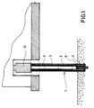
- FIG. 1 shows a partially sectioned illustration of a press pile 1 and a press 12, as well as parts of the building to be lifted and the subsurface. Below a load-bearing outer wall, only as much space had to be created as the press 12 and a press pile segment 2 or 3 require in space.
- the reaction force to apply the pressure is applied by the weight of the building. It is imperative that the reaction force from the weight of the building must be greater than that from the resistance of the ground at the time the pile is founded Reactive power, otherwise the building would be lifted at this point.
- the reaction force for the introduction of a single (or fewer) press piles 1 can be applied by the building. If, after completion of the foundation of all press piles 1, a lifting element is pressurized on each press pile 1, the entire building rises. In this way, the same hydraulic elements can advantageously be used first for the introduction of the press piles 1 and then for the lifting of the building.
- the press pile 1 as a whole is therefore not further pressed in according to the invention, but inner segments with a smaller cross section described in more detail in FIG .
- the various inner segments can be extended telescopically, the next smaller inner segments each being extended further when the peak pressure or the jacket friction has exceeded a predetermined value.
- the uppermost inner segments can be very thin-walled and made of steel, for example.
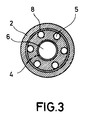
- FIG. 2 shows a press pile 1, which is composed of an initial segment 2 and any number of subsequent segments 3.
- segments 2, 3 there are several axially extending recesses.
- a large recess 4 runs directly centrally, several smaller reinforcement recesses 5 are arranged concentrically around the central axis of the segment.
- the reinforcement recesses in the starting segment 2 are designed as blind holes.
- An inner segment 6 is located within the recess 4.
- the underside of the press pile 1 is thus closed, and separating layers in the subsurface can be punctured, without the risk that the earth's physics of the individual layers are changed by compensating processes, for example water movements.
- a reinforcing steel 7 inserted into a reinforcement recess 5 is drawn as an example for all other reinforcement recesses 5.
- the reinforcement recesses 5 In order to enable a continuous insertion of the reinforcement steels 7, the reinforcement recesses 5 must be aligned over the entire length of the column 1, which is known to consist of a large number of subsequent segments 3.
- the alignment can take place, for example, by visual inspection when the next following segment 5 is placed on it, or it can be forcibly carried out by coding on the top and bottom sides of the press pile segments 2, 3.
- Such coding can be implemented, for example, in the form of grooves and corresponding projections. For the sake of clarity, the projections and grooves are not shown in this illustration.
- the individual press pile segments 2, 3 each have a helical reinforcement 8 made of steel. Due to the combination of spiral reinforcement 8, the reinforcing steel 7 passing through and the reinforcement recesses 5 poured with concrete, the press piles 1 according to the invention receive a non-positive connection and the predictable statics of a column.
- the inner segment 6 can be pressed telescopically out of the press pile 1. Because the inner segment 6 has a significantly smaller cross-section, the inner segment 6 can achieve a significantly higher surface pressure due to the building weight acting on the press pile 1.
- a press is used which only presses on the inner segment 6. This is particularly advantageous if, for example, the entire press pile 1 has penetrated the poorly load-bearing layers of the subsurface and stands on a load-bearing gravel layer. then the pressure on the inner segment 6 can "extend" it telescopically from the press pile 1 and thus bring about an improved anchoring of the press pile 1, which stands on the gravel layer, in this gravel layer.
- FIG. 3 shows a section along the section line II-II from FIG. 1, the position of the centrally running recess and the concentrically arranged reinforcement recesses can be clearly seen.
- FIG. 9 An embodiment for an application in which the original foundation has to be reinforced is shown in FIG.
- reinforcement is carried out by an auxiliary foundation 9 attached below the foundation.
- the soil beneath the foundations is removed at certain points near the load-bearing wall under which a press pile 1 will later be placed, inside or outside the building, and continuously or relatively continuously by an armored or non-armored person Concrete to be replaced.
- a plurality of tension struts 10 are anchored in the auxiliary foundation 9 thus created.
- the free ends of the tension struts 10 protruding from the auxiliary foundation 9 are connected to a stable supporting frame 11.
- the press 12 is supported on this support frame 11.
- FIG. 1 A schematic representation of a possible arrangement of a plurality of press piles 1/1 .. 1/16 under the outer walls of a building is shown in FIG.
- a partial amount of the press piles is pressurized to insert the press piles.
- the second, fourth, sixth, etc. press piles 1/2, 1/4, 1/6, ... are inserted.
- any other distribution is also conceivable, only the principle is to be explained here, namely, when inserting the press piles, alternately loading only a subset of all press piles used later for lifting.
- the method according to the invention further provides not to first bring one or more press piles all the way down to the load-bearing layer, but rather to insert all press piles approximately equally deep in the individual phases.
- the first segments of the first press pile group are pressed in, then the initial segments of the second press pile group are pressed in.
- the individual indentation steps are very small. They are preferably in the range of a few millimeters.
- the second segments of the first press pile group are pressed in, then the second segments of the second press pile group.
- the pressing in of the pile segments 2, 3 is carried out under computer control by a control unit 13, the pressing speed being kept constant for each pressing pile and the pressing pressure being stored as a function of the pressing depth.
- the respective press pile When the next following segment is put on, the respective press pile is relieved.
- the elastic part of the settlement is determined from the relief movement. The smaller this elastic part is, the closer the starting segment of the press pile 1 is to a load-bearing layer.
- press piles (1/1 to 1/16) in a first step all press piles (1/1 to 1/16) can be pressed in simultaneously, and in a second step when pressing in the press piles (1/1 to 1/16) alternately a first subset of press piles ( 1/1, 1/3, 1/5, ..) and a second subset (1/2, 1/4, .1 / 6, ..) or vice versa.
- This enables an optimal adaptation to the local soil conditions.
- the forces opposing the individual press piles are also checked when they are pressed in. If the press-in force is not the same, readjustment is carried out via the press-in path, so that a force transmission is evenly distributed over all press piles.
Landscapes
- Engineering & Computer Science (AREA)
- Structural Engineering (AREA)
- Life Sciences & Earth Sciences (AREA)
- General Life Sciences & Earth Sciences (AREA)
- Mining & Mineral Resources (AREA)
- Paleontology (AREA)
- Civil Engineering (AREA)
- General Engineering & Computer Science (AREA)
- Placing Or Removing Of Piles Or Sheet Piles, Or Accessories Thereof (AREA)
Abstract
Description
Die Erfindung bezieht sich auf ein Verfahren gemäß Anspruch 1 und eine Vorrichtung zur Durchführung des Verfahrens gemäß Anspruch 13.The invention relates to a method according to
Pfahlgründungen sind in verschiedensten Baubereichen erforderlich.Pile foundations are required in a wide variety of construction areas.
Zum einen bei Neubauten, wenn der Baugrund nicht die erforderliche Festigkeit aufweist und zum anderen bei Sanierungen bestehender Gebäude, die infolge einer Schwäche des Untergrunds sich bewegt (gesenkt, gehoben und/oder verwunden) haben.On the one hand in new buildings if the building ground does not have the required strength and on the other hand in the renovation of existing buildings that have moved (lowered, raised and / or twisted) due to a weakness of the subsoil.
Seit Jahrtausenden ist bereits der Einsatz von Rammpfählen bekannt. So sind beispielsweise die historischen Pfahlbauten auf Rammpfählen errichtet. Aus der Länge der Rammpfähle ergibt sich eine gewisse Begrenzung, die sich auf die maximal mögliche Tiefe der Pfahlgründung auswirkt.The use of driven piles has been known for thousands of years. For example, the historic pile dwellings are built on ram piles. There is a certain limitation from the length of the driven piles, which affects the maximum possible depth of the pile foundation.
Ein weiterer Nachteil der Rammpfahl-Technik ist es, daß dieses Verfahren stets mit einer Erschütterung des Erdbodens und somit auch umgebender Gebäude verbunden ist. Durch die Erschütterungen können an den betreffenden Gebäuden Schäden auftreten, daher scheidet der Einsatz von Rammpfählen für die nachträgliche Pfahlgründung von erschütterungs empfindlichen Gebäuden aus.Another disadvantage of the pile-driving technique is that this method is always associated with a vibration of the ground and thus also surrounding buildings. The vibrations can cause damage to the buildings in question, so the use of ram piles for the subsequent pile foundation of buildings that are sensitive to vibrations is ruled out.
Bekannt sind ferner Bohrpfähle, bei deren Verwendung auf ein Rammen der Pfähle verzichtet wird. Bei diesem Verfahren schneidet sich der Schneidkopf eines Rohres in das Erdreich. Das Rohr hat eine doppelte Funktion. Einerseits dient es zum Einschneiden in das Erdreich, andererseits wirkt es gegenüber dem umgebenden Erdreich wie eine Schalung oder eine Brunnenwand, d. h. das umgebende Erdreich ist in physikalischer Hinsicht vollkommen vom Erdreich im Inneren des Rohres getrennt. Das Innere des Rohres kann nun mit geeigneten Baggern, sogenannten Fallbaggern ausgebaggert werden. In dem so entstandenen Hohlraum wird in üblicher Weise anschließend eine Baustahlbewehrung eingebracht und der gesamte Hohlraum mit Beton aufgefüllt.Also known are bored piles, the use of which means that the piles are not rammed. With this method, the cutting head of a pipe cuts into the ground. The pipe has a dual function. On the one hand, it serves to cut into the ground, on the other hand it acts like a formwork or a well wall in relation to the surrounding ground, ie the surrounding ground is physically completely separated from the ground inside the pipe. The inside of the pipe can now be dredged with suitable excavators, so-called fall excavators. In the resulting cavity is then a in the usual way Reinforced steel reinforcement and the entire cavity filled with concrete.
Ein Bohrpfahl ist somit vergleichbar mit einer in der Erde befindlichen Säule mit Schalung (= Rohr). Die hierzu in Einsatz befindlichen kombinierten Bohr- und Baggergeräte sind üblicherweise mehrere Tonnen schwer und müssen, um für den Fallbagger eine entsprechende Fallhöhe zu besitzen, sehr hoch sein.A bored pile is therefore comparable to a column with formwork (= pipe) located in the ground. The combined drilling and excavation equipment used for this purpose is usually several tons heavy and must be very high in order to have a suitable fall height for the fall excavator.
Aus diesen Gründen ist der Einsatz derartiger Geräte bei beengten räumlichen Verhältnissen ebenso wenig möglich, wie der gleichzeitige Einsatz mehrerer entsprechender Geräte nah beieinander. Sollen nach diesem Verfahren mehrere Pfähle ineinander angeordnet werden, um beispielsweise einen Sprundwandefekt zu erzielen, so werden mehrere Bohrungen in der Weise nebeneinander angebracht, daß die benachbarte Bohrung erst dann niedergebracht wird, wenn sich in der vorangegangenen Bohrung der betonierte Pfahl befindet.For these reasons, the use of such devices in tight spaces is just as impossible as the simultaneous use of several corresponding devices close to each other. If, according to this method, several piles are to be arranged one inside the other in order, for example, to achieve a wall defect, several holes are drilled side by side in such a way that the adjacent hole is only drilled when the concrete pile is in the previous hole.
Ein weiterer Nachteil der Bohrpfähle besteht darin, daß im Gegensatz zu den Rammpfählen, die im Pfahlbereich eine Verdichtung des umgebenen Grunds bewirken, bei Bohrpfählen diese eine relativ geringe Auswirkung auf die Physik des umgebenen Erdreichs bewirken und vorhandene Schichten somit ohne wesentliche Veränderung durchstossen werden. Dieses Durchstossen kann zu unterschiedlichsten Folgen führen. Wenn beispielsweise eine tiefere wasserführende Erdschicht mit einem höheren Druck durch eine Sperrschicht von einer höheren wasserführenden oder nicht wasserführenden Erdschicht mit niedrigeren Druckverhältnissen getrennt ist, so kann durch den Bohrvorgang entlang des Schneidrohres Wasser von der unteren wasserführenden Schicht infolge des höheren Drucks nach oben aufsteigen und die dortige Erdphysik verändern.Another disadvantage of bored piles is that, unlike rammed piles, which compact the surrounding ground in the area of the piles, bored piles have a relatively small effect on the physics of the surrounding soil and the existing layers are penetrated without any significant change. This puncture can lead to various consequences. If, for example, a deeper water-bearing earth layer with a higher pressure is separated by a barrier layer from a higher water-bearing or non-water-bearing earth layer with lower pressure ratios, the drilling process along the cutting tube can cause water to rise from the lower water-bearing layer due to the higher pressure and the change earth physics there.
Oberflächennahe verunreinigte Wasserströme können mit tiefergelegenen Trinkwasserströmen in nicht gewünschter Weise vermischt werden etc.Contaminated water flows near the surface can be mixed with deeper lying drinking water flows in an undesired manner etc.
Bei Torfschichten gelangt an der Schnittstelle unter Umständen Luft an den Torf, was gegebenfalls zu einer langfristigen Veränderung der Konsistenz des Untergrundes (z.B. Zersetzung des Torfes durch eindringende Bakterien) führen kann.With peat layers, air may get to the peat at the interface, which may lead to a long-term change in the consistency of the subsoil (e.g. decomposition of the peat by penetrating bacteria).
Ein bedeutender Nachteil sowohl bei der Bohrpfahlgründung als auch der Rammpfahlgründung ergibt sich aus dem Platzbedarf der Bohrer bzw Rammen zum Einbringen der Pfähle wodurch ein gleichzeitiges Einbringen mehrerer nahe benachbarter Pfähle unmöglich ist.A significant disadvantage of both the bored pile foundation and the driven pile foundation results from the space required by the drill or ram to insert the piles, making it impossible to insert several adjacent piles at the same time.
Ein weiterer Nachteil sowohl der Rammpfahlgründung, als auch der Bohrpfähle ist, daß bei beiden Verfahren die Pfähle nicht senkrecht unterhalb tragender Mauern bestehender Gebäude angebracht werden können.Another disadvantage of both the pile pile foundation and the bored piles is that in both methods the piles cannot be installed vertically below the supporting walls of existing buildings.
Aus der DE-OS 37 39 917 ist ein Verfahren und eine Vorrichtung zum Durchführen des Verfahrens bekannt, bei welchem unterhalb tragender Mauern Pfähle eingebracht werden können. Dazu wird an mehreren Stellen des auszurichtenden Gebäudes unter dem Fundament eine ausreichend große Arbeitsgrube geschaffen, um darin jeweils Presspfahlseqmente und hydraulische Pressen einbringen zu können. Durch den Hebedruck der am Fundament des zu hebenden Gebäudes dringen die Presspfahlseqmente in den Untergrund, worauf das nächste Presspfahlseqment auf das zuvor eingepresste Presspfahlsegment gesetzt wird.From DE-OS 37 39 917 a method and a device for carrying out the method is known, in which piles can be inserted below load-bearing walls. For this purpose, a sufficiently large working pit is created under the foundation at several points of the building to be aligned in order to be able to incorporate press pile segments and hydraulic presses. As a result of the lifting pressure on the foundation of the building to be lifted, the press pile segments penetrate into the ground, whereupon the next press pile segment is placed on the previously pressed press pile segment.
Bei weicher Konsistenz des Untergrundes und gleichzeitig notwendiger großer Gründungstiefe müssen viele Segmente aufeinander gesetzt werden. Wegen der geringen seitlichen Einspannkräfte durch den weichen Untergrund besteht die Gefahr, daß der nach dem bekannten Verfahren erstellte Gründungspfahl seitlich einknickt. Um dies zu vermeiden müßte der Presspfahl die Eigenschaften einer festen Säule aufweisen.With a soft consistency of the subsurface and at the same time a large foundation depth is necessary, many segments must be placed on top of each other. Because of the low lateral clamping forces due to the soft surface, there is a risk that the foundation pile created according to the known method will buckle laterally. To avoid this, the press pile should have the properties of a solid column.
Beim Stand der Technik sind die Segmente nicht zugfest miteinander verbunden. Eine statisch berechenbare Säule läßt sich so nicht realisieren. Dies ist besonders dann von Nachteil, wenn die tragfähige Schicht weit unter dem Niveau des Gebäudefundaments liegt und/oder wenn durch Absenkung des Grundwasserspiegels eine Setzung des Untergrundes auftritt.In the prior art, the segments are not connected to one another with tensile strength. A statically calculable column cannot be realized in this way. This is particularly disadvantageous if the load-bearing layer is far below the level of the building foundation and / or if the subsoil settles due to the lowering of the groundwater level.
Auch aufgrund der mit zunehmender Einpresstiefe auftretenden Mantelreibung am Presspfahl ist beim Stand der Technik die maximale Einpresstiefe begrenzt.The maximum press-in depth is also limited in the prior art due to the skin friction on the press pile which occurs with increasing press-in depth.
Der Erfindung liegt die Aufgabe zugrunde ein Verfahren anzugeben und eine Vorrichtung zur Durchführung des Verfahrens schaffen, womit die Nachteile des Standes der Technik vermieden werden.The invention has for its object to provide a method and create an apparatus for performing the method, whereby the disadvantages of the prior art are avoided.
Diese Aufgabe wird erfindungsgemäß durch ein Verfahren gemäß des kennzeichnenden Teils des Anspruches 1 und durch eine Vorrichtung gemäß des kennzeichnenden Teils des Anspruchs 13 gelöst.This object is achieved according to the invention by a method according to the characterizing part of
Die Erfindung macht sich dabei die Erkenntnis zu eigen, daß bei weichem Untergrund eine Vielzahl von Presspfahlsegmenten übereinander angeordnet werden müssen und diese durch entsprechende Maßnahmen zugfest miteinander verbunden sein müssen, um eine statisch berechenbare Säule zu schaffen, auf welcher das Gebäude letztendlich steht.The invention adopts the knowledge that a large number of pressed pile segments must be arranged one above the other on soft ground and that these must be connected to one another in a tensile manner by appropriate measures in order to create a statically calculable column on which the building ultimately stands.
Eine weitere Überlegung die zur Entstehung der Erfindung geführt hat, geht davon aus, daß mit zunehmender Einpresstiefe die Mantelreibung an den Aussenflächen der bereits eingepressten Segmente so groß wird, daß dadurch ein großer Teil des Pressdruckes aufgenommen wird und der Stitzendruck des untersten Segments zu gering ist um es noch tiefer eindringen zu lassen. Daher ist es vorgesehen aus dem untersten Segment ein oder mehrere weitere Segmente mit geringerem Querschnitt teleskopartig herauszudrücken.Another consideration that led to the creation of the invention is based on the fact that with increasing press-in depth, the skin friction on the outer surfaces of the already pressed-in segments becomes so great that a large part of the press-pressure is thereby absorbed and the seat pressure of the lowermost segment is too low to make it go deeper. It is therefore provided that one or more further segments with a smaller cross section are telescopically pressed out of the lowest segment.
Weiterbildungen und besonders vorteilhafte Ausgestaltungen der Erfindung sind Gegenstand der Unteransprüche.Developments and particularly advantageous embodiments of the invention are the subject of the dependent claims.
Nachfolgend wird ein mögliches Ausführungsbeispiel der Erfindung anhand der Zeichnung näher erläutert.A possible exemplary embodiment of the invention is explained in more detail below with reference to the drawing.
Es zeigen:
Figur 1- in Teils gebrochener Darstellung den Einsatz der Erfindung an einem Gebäude
Figur 2- einen Längsschnitt durch das Anfangssegment des Presspfahles und ein darauf aufgesetztes Folgesegment.
Figur 3- einen Querschnitt durch das Anfangssegment gemäß
Figur 2 entlang der Schnittlinie II-II Figur 4- einen Querschnitt durch das Fundament eines Hauses, dessen ursprüngliches Fundament durch ein Hilfsfundament verstärkt wurde
Figur 5- in schematischer Darstellung die Lage einer Vielzahl von Presspfählen unter einem Gebäude.
- Figure 1
- partly broken representation of the use of the invention on a building
- Figure 2
- a longitudinal section through the initial segment of the press pile and a subsequent segment placed thereon.
- Figure 3
- a cross section through the starting segment of Figure 2 along the section line II-II
- Figure 4
- a cross section through the foundation of a house, the original foundation of which was reinforced by an auxiliary foundation
- Figure 5
- the location of a plurality of press piles under a building in a schematic representation.
Figur 1 zeigt in teils geschnittener Darstellung einen Presspfahl 1 und eine Presse 12, sowie Teile des zu hebenden Gebäudes und des Untergrundes. Unterhalb einer tragenden Aussenwand mußte lediglich so viel Raum geschaffen werden, wie die Presse 12 und ein Presspfahlsegment 2 bzw. 3 an Platz benötigen. Die Reaktionskraft zur Aufbringung des Drucks wird hierbei durch das Gewicht des Gebäudes aufgebracht. Es ist hierbei zwingend notwendig, daß zum Zeitpunkt der Pfahlgründung die vom Gewicht des Gebäude kommende Reaktionskraft größer sein muß, als die vom Widerstand des Erdreichs kommende Reaktionskraft, an ansonsten bereits zu diesem Zeitpunkt das Gebäude gehoben würde.FIG. 1 shows a partially sectioned illustration of a
Um ein ungewolltes Anheben des Gebäudes bereits beim Einbringen der Presspfähle 1 zu vermeiden ist es erfindungsgemäß vorgesehen, bei der Gründung mehrerer nebeneinander liegender Presspfähle 1 diese segmentweise nacheinander einzupressen, wodurch erreicht wird, daß die Anfangssegmente aller Presspfähle zu jedem Zeitpunkt des Einbringens etwa in gleicher Tiefe gründen (Wird in Figur 5 näher erläutert).In order to avoid an unintentional lifting of the building when inserting the press piles 1, it is provided according to the invention to press these in segments one after the other when founding
Die Reaktionskraft für das Einbringen eines einzigen (oder weniger) Presspfahles 1 (-pfähle) kann hierbei von dem Gebäude aufgebracht werden. Wenn nach Beendigung der Gründung aller Presspfähle 1 an jedem Presspfahl 1 ein Hubelemente mit Druck beaufschlagt werden, so hebt sich das gesamte Gebäude. Auf diese Weise können vorteilhaft dieselben hydraulischen Elemente zuerst für das Einbringen der Presspfähle 1 und anschließend für das Heben des Gebäudes verwendet werden.The reaction force for the introduction of a single (or fewer) press piles 1 (piles) can be applied by the building. If, after completion of the foundation of all
Ab einer gewissen Einpresstiefe nimmt der Widerstand gegen ein weiteres Einpressen auch aufgrund der Mantelreibung an der Aussenseite des Presspfahles 1 zu. Ein weiterse Einpressen würde unter Umständen so hohe Kräfte erfordern, daß die Belastung an der als Widerlager für die Presse 12 dienenden Fundamentstelle so groß werden würde, daß eine Beschädigung des Gebäudes zu befürchten wäre. Gleichwohl befindet sich aber das Anfangssegment des Presspfahles 1 noch nicht auf einer tragenden Schicht.From a certain press-in depth, the resistance to further press-in also increases due to the skin friction on the outside of the
Ab einer gewissen Gründungstiefe, die jeweils von der Beschaffenheit des Untergrundes und der Belastbarkeit des zu hebenden Gebäudes abhängt, wird daher erfindungsgemäß der Presspfahl 1 als Ganzes nicht weiter eingedrückt, sondern es werden in Figur 2 näher beschriebene Innensegmente mit geringerem Querschnitt weiter in den Untergrund gedrückt.From a certain depth of foundation, which depends in each case on the nature of the subsoil and the load-bearing capacity of the building to be lifted, the
Dabei können je nach Anforderung auch mehrere Innensegmente mit unterschiedlichem Durchmesser ineinander angeordnet, wobei das jeweils kleinere Innensegment dann weitergepreßt wird, wenn der zum Einpressen aufzuwendende Druck eine vorgegebene Grenze erreicht hat.Depending on the requirement, several inner segments with different diameters can also be arranged one inside the other, the smaller inner segment being pressed further when the pressure to be pressed in has reached a predetermined limit.
Auf diese Weise kann tief in die beginnend tragfähigen Schichten eingepreßt werden und aufgrund der eingetretenen Mantelreibung an den Segmenten 2, 3 mit großem Durchmesser wird bereits ein Teil der Fundamentlasten aufgenommen.In this way, it is possible to press deeply into the load-bearing layers, and due to the skin friction on the
Bei großen Gründungstiefen können die verschiedenen Innensegmente mit jeweils geringerem Innendurchmesser teleskopartig ausgefahren werden, wobei die nächst kleineren Innensegmente jeweils dann weiter ausgefahren werden, wenn der Spitzendruck oder die Mantelreibung einen vorbestimmten Wert überschritten hat.In the case of large foundation depths, the various inner segments, each with a smaller inner diameter, can be extended telescopically, the next smaller inner segments each being extended further when the peak pressure or the jacket friction has exceeded a predetermined value.
Die obersten Innensegmente können dabei sehr dünnwandig sein und zB aus Stahl bestehen.The uppermost inner segments can be very thin-walled and made of steel, for example.
In Figur 2 erkennt man einen Presspfahl 1, der aus einem Anfangsegment 2 und beliebig vielen Folgesegmenten 3 zusammengesetzt ist. In den Segmenten 2, 3 befinden sich mehrere axial verlaufende Aussparungen. Eine große Aussparung 4 verläuft direkt zentral, mehrere kleinere Bewehrungsaussparungen 5 sind konzentrisch um die Mittelachse des Segments angeordnet.2 shows a
Im Gegensatz zu den durchgehenden Bewehrungsaussparungen in den Folgesegmenten 3 sind die Bewehrungsaussparungen im Anfangssegment 2 als Sacklöcher ausgeführt. Innerhalb der Aussparung 4 befindet sich ein Innensegment 6.In contrast to the continuous reinforcement recesses in the following
Die Unterseite des Presspfahls 1 ist somit geschlossen, ein Durchstoßen von Trennschichten im Untergrund kann so vorgenommen werden, ohne daß die Gefahr besteht, daß die Erdphysik der einzelnen Schichten durch Ausgleichsvorgänge z.B. Wasserbewegungen verändert wird.The underside of the
Beispielhaft für alle anderen Bewehrungsaussparungen 5 ist ein in eine Bewehrungsaussparung 5 eingesetzter Bewehrungsstahl 7 gezeichnet.A reinforcing
Um ein durchgehendes Einschieben der Bewehrungsstähle 7 zu ermöglichen müssen die Bewehrungsaussparungen 5 über die gesamte Länge der -bekanntlich aus einer Vielzahl von Folgesegmenten 3 bestehenden- Säule 1 fluchten. Das Fluchten kann beispielsweise durch optische Kontrolle beim Aufsetzen des jeweils nächsten Folgesegmentes 5 erfolgen oder zwangsweise durch eine Codierung an den Ober-und Unterseiten der Presspfahlsegmente 2, 3 erfolgen. Eine solche Codierung läßt sich etwa in Form von Nuten und dazu korrespondierenden Vorsprüngen realisieren. Aus Gründen der Übersichtlichkeit sind die Vorsprünge und Nuten in dieser Darstellung nicht gezeigt.In order to enable a continuous insertion of the reinforcement steels 7, the reinforcement recesses 5 must be aligned over the entire length of the
Die einzelnen Presspfahlsegmente 2, 3 besitzen jeweils eine Wendelbewehrung 8 aus Stahl. Durch die Kombination aus Wendelbewehrung 8, den durchgebenden Bewehrungsstählen 7 und den mit Beton ausgegossenen Bewehrungsausparungen 5 erhalten die erfindungsgemäßen Presspfähle 1 eine kraftschlüssige Verbindung und die berechenbare Statik einer Säule.The individual
Wie ersichtlich läßt sich das Innensegment 6 teleskopartig aus dem Presspfahl 1 nach unten drücken. Dadurch, daß das Innensegment 6 einen deutlich geringeren Querschnitt aufweist, läßt sich durch das Innensegment 6 durch das auf den Presspfahl 1 wirkende Gebäudegewicht ein wesentlich höherer Flächendruck erreichen. Dazu wird eine Presse verwendet, die nur auf das Innensegment 6 drückt. Dies ist besonders dann von Vorteil, wenn beispielsweise der gesamte Presspfahl 1 die schlecht tragenden Schichten des Untergrunds durchstossen hat und auf einer tragenden Kiesschicht aufsteht, dann kann durch den Druck auf das Innensegment 6 dieses teleskopartig aus dem Presspfahl 1 "ausfahren" und so eine verbesserte Verankerung des Presspfahls 1, der auf der Kiesschicht steht, in dieser Kiesschicht bewirken.As can be seen, the
In Figur 3 ist ein Schnitt entlang der Schnittlinie II-II aus Figur 1 dargestellt, die Lage der zentral verlaufenden Ausnehmung und der konzentrisch angeordneten Bewehrungsausnehmungen ist deutlich zu erkennen.FIG. 3 shows a section along the section line II-II from FIG. 1, the position of the centrally running recess and the concentrically arranged reinforcement recesses can be clearly seen.
Eine Ausführungsform für einen Einsatz bei dem das ursprüngliche Fundament verstärkt werden muß ist in Figur 4 gezeigt. Dazu erfolgt eine Verstärkung durch einen unterhalb des Fundaments angebrachten Hilfsfundament 9. Dazu wird nahe der tragenden Mauer unter welcher später ein Presspfahl 1 stehen soll innerhalb oder außerhalb des Gebäudes punktuell das Erdreich unter den Fundamenten entfernt und kontinuierlich oder relativ kontinuierlich durch einen bewehrten oder nicht bewehrten Beton zu ersetzt. Ebenso besteht die Möglichkeit den Untergrund durch Betoninjektionen zu befestigen. In diesem so entstandenen Hilfsfundament 9 werden mehrere Zugstreben 10 verankert. Die aus dem Hilfsfundament 9 herausragenden freien Enden der Zugstreben 10 sind mit einem stabilen Tragrahmen 11 verbunden. An diesen Tragrahmen 11 stützt sich die Presse 12 ab. Bei der Pfahlgründung wird somit das gesamte Gewicht des Gebäudes auf dieses zweite Fundament ein, so daß ein stabiles Widerlager vorhanden ist. Das Gebäude steht mit seinem Fundament sozusagen auf diesem zweiten Fundament und wird im anschließenden Hubvorgang mit diesem zweiten Fundament bewegt, d. h. im Regelfall gehoben.An embodiment for an application in which the original foundation has to be reinforced is shown in FIG. For this purpose, reinforcement is carried out by an
Eine schematisierte Darstellung einer möglichen Anordnung einer Vielzahl von Presspfählen 1/1 .. 1/16 unter den Aussenmauern eines Gebäudes ist in Figur 5 gezeigt. Zum Einbringen der Presspfähle wird jeweils eine Teilmenge der Presspfähle mit Druck beaufschlagt. Um nicht bereits beim Einbringen der Presspfähle eine lokale Anhebung des Gebäudes zu bewirken werden vorzugsweise der jeweils erste , dritte, fünfte usw. Presspfahl 1/1, 1/3, 1/5,... gemeinsam niedergebracht. In einem zweiten Schritt werden der zweite, der vierte, sechste usw Presspfahl 1/2, 1/4, 1/6,... eingebracht. Natürlich ist auch jede beliebige andere Verteilung denkbar, es soll hier nur das Prinzip erklärt werden, nämlich beim Einbringen der Presspfähle wechselweise nur eine Teilmenge aller später beim Heben zum Einsatz kommenden Presspfähle zu belasten.A schematic representation of a possible arrangement of a plurality of
Das erfindungsgemäße Verfahren sieht weiters vor, nicht zuerst einen oder mehrere Presspfähle vollständig bis zu der tragenden Schicht niederzubringen sondern alle Presspfähle in den einzelnen Phasen etwa gleich tief einzubringen. Dazu werden die ersten Segmente der ersten Presspfahlgruppe eingedrückt, dann werden die Anfangssegmente der zweiten Presspfahlgruppe eingedrückt. Die einzelnen Eindrückschritte sind sehr klein. Sie liegen vorzugsweise im Bereich von einigen Millimeter.The method according to the invention further provides not to first bring one or more press piles all the way down to the load-bearing layer, but rather to insert all press piles approximately equally deep in the individual phases. For this purpose, the first segments of the first press pile group are pressed in, then the initial segments of the second press pile group are pressed in. The individual indentation steps are very small. They are preferably in the range of a few millimeters.
Im nächsten Schritt werden die zweiten Segmente der ersten Presspfahlgruppe eingedrückt, daraufhin die zweiten Segmente der zweiten Presspfahlgruppe.In the next step, the second segments of the first press pile group are pressed in, then the second segments of the second press pile group.
Das Eindrücken der Pfahlsegmente 2, 3 wird computergesteuert durch eine Steuereinheit 13 durchgeführt, wobei für jeden Presspfahl die Einpressgeschwindigkeit konstant gehalten wird und der Einpressdruck in Abhängigkeit von der Einpresstiefe gespeichert wird.The pressing in of the
Beim Aufsetzen des jeweils nächsten Folgesegments wird der jeweilige Presspfahl entlastet. Aus der Entlastungsbewegung wird der elastische Anteil der Setzung ermittelt. Je geringer dieser elastische Teil ist, desto näher befindet sich das Anfangssegment des Presspfahles 1 an einer tragfähigen Schicht.When the next following segment is put on, the respective press pile is relieved. The elastic part of the settlement is determined from the relief movement. The smaller this elastic part is, the closer the starting segment of the
So wird für jeden einzelnen Presspfahl 1 dessen spezifisches Tragverhalten gemessen und steht für spätere Nachweise der Standsicherheit zur Verfügung.Thus, the specific load-bearing behavior is measured for each
Durch das gemeinsame Eindrücken in kleinen, gleichzeitigen Einpressschritten wird erfindungsgemäß erreicht, daß die Anfangssegmente aller Presspfähle 1/1 bis 1/16 sich in etwa auf der gleichen Ebene im Untergrund befinden. Dies hat gegenüber einem nacheinander erfolgenden, vollständigen Einbringen der einzelnen Pfähle bis zur Gründungsebene den Vorteil, daß eine unerwünschte Veränderung des Untergrundes -hervorgerufen durch das vollständige Einbringen des vorangegangenen Presspfahls 1 hier nicht auftritt. Eine solche unerwünschte Veränderung wäre beispielsweise ein Ausgleich unterschiedlicher Porenwasserdrücke in den unterschiedlichen Gründungstiefen.By pressing them together in small, simultaneous press-in steps it is achieved according to the invention that the starting segments of all
In erfindungsgemäßerweise können in einem 1. Schritt alle Presspfähle (1/1 bis 1/16) gleichzeitig eingedrückt werden, und in einem 2. Schritt beim Eindrücken der Presspfähle (1/1 bis 1/16) jeweils abwechselnd eine erste Untermenge von Presspfählen (1/1, 1/3, 1/5,..) und eine zweite Untermenge (1/2, 1/4,.1/6,..) eingedrückt werden oder umgekehrt. Hierdurch ist eine optimale Anpassung an die örtlichen Bodenverhältnisse möglich.According to the invention, in a first step all press piles (1/1 to 1/16) can be pressed in simultaneously, and in a second step when pressing in the press piles (1/1 to 1/16) alternately a first subset of press piles ( 1/1, 1/3, 1/5, ..) and a second subset (1/2, 1/4, .1 / 6, ..) or vice versa. This enables an optimal adaptation to the local soil conditions.
In einer weitergehenden Ausgestaltung der EErfindung erfolgt beim Eindrücken zudem eine Kontrolle der von den einzelnen Presspfählen entgegengesetzten Kräfte. Wenn die Eindrückkraft nicht gleich ist, wird über den Einpressweg nachgeregelt, so daß eine gleichmäßg auf alle Presspfähle verteilte Kraftübertragung erfolgt.In a further development of the invention, the forces opposing the individual press piles are also checked when they are pressed in. If the press-in force is not the same, readjustment is carried out via the press-in path, so that a force transmission is evenly distributed over all press piles.
Bei dem erfindungsgemäßen Verfahren kann es demnach nicht folgender Fall auftreten, daß etwa bei einem schräg verlaufenden Sand/Fels-Übergang ein Teil der Presspfähle auf dem Fels gründet, der andere Teil aber noch vollkommen im Sand steht.Accordingly, in the method according to the invention, the following case cannot occur that, for example, in the case of an inclined sand / rock transition, part of the press piles is based on the rock, but the other part is still completely in the sand.
Claims (17)
dadurch gekennzeichnet, daß
die einzelnen Segmente (2,3) so übereinander gesetzt werden, daß die Aussparungen (4,5) jeweils fluchtend angeordnet sind.Method according to claim 1,
characterized in that
the individual segments (2, 3) are placed one above the other so that the recesses (4, 5) are each aligned.
dadurch gekennzeichnet, daß
die einzelnen Segmente (2,3) aus Stahlbeton hergestellt sind und eine Wendelbewehrung (8) aus Stahl nahe der innerhalb von ihr liegenden Aussparungen (5) aufweisen.A method according to claim 1 or claim 2,
characterized in that
the individual segments (2, 3) are made of reinforced concrete and have a helical reinforcement (8) made of steel near the recesses (5) lying within them.
dadurch gekennzeichnet, daß
die einzelnen Segmente (2,3) aus Stahl hergestellt sind.A method according to claim 1 or claim 2,
characterized in that
the individual segments (2,3) are made of steel.
dadurch gekennzeichnet, daß
characterized in that
dadurch gekennzeichnet, daß
die Innensegmente (6) nach dem Aushärten des in die Aussparungen (5) eingebrachten Vergußmaterials weitergepreßt werden.Method according to one or more of the preceding claims 1 to 6,
characterized in that
the inner segments (6) are pressed further after the potting material introduced into the recesses (5) has hardened.
dadurch gekennzeichnet, daß
characterized in that
dadurch gekennzeichnet, daß
characterized in that
dadurch gekennzeichnet, daß
characterized in that
dadurch gekennzeichnet, daß
die Segmente (2,3) im Verlauf der einzelnen Segmente fluchtende Ausnehmungen (4,5) aufweisen.Device for carrying out the method according to claim 1, consisting of a press and a plurality of stackable pile segments
characterized in that
the segments (2, 3) have aligned recesses (4, 5) in the course of the individual segments.
dadurch gekennzeichnet, daß
in den Segmenten (2,3) jeweils Innensegmente (6) angeordnet sind, die unabhängig von den Segmenten (2,3) einpressbar sind.Device according to claim 15,
characterized in that
inner segments (6) are arranged in each of the segments (2, 3) and can be pressed in independently of the segments (2, 3).
dadurch gekennzeichnet, daß
characterized in that
Applications Claiming Priority (2)
| Application Number | Priority Date | Filing Date | Title |
|---|---|---|---|
| DE19924224042 DE4224042A1 (en) | 1992-07-21 | 1992-07-21 | Method and device for pile foundation |
| DE4224042 | 1992-07-21 |
Publications (1)
| Publication Number | Publication Date |
|---|---|
| EP0580098A1 true EP0580098A1 (en) | 1994-01-26 |
Family
ID=6463760
Family Applications (1)
| Application Number | Title | Priority Date | Filing Date |
|---|---|---|---|
| EP93111516A Withdrawn EP0580098A1 (en) | 1992-07-21 | 1993-07-18 | Method and device for pile foundation |
Country Status (2)
| Country | Link |
|---|---|
| EP (1) | EP0580098A1 (en) |
| DE (1) | DE4224042A1 (en) |
Cited By (17)
| Publication number | Priority date | Publication date | Assignee | Title |
|---|---|---|---|---|
| RU2144111C1 (en) * | 1999-07-20 | 2000-01-10 | Кушнарев Сергей Михайлович | Method for fortifying foundation of building |
| DE19917253A1 (en) * | 1999-04-16 | 2000-11-02 | Hock Berghaus Kay | Fabrication process for bending-resistant piles below existing foundations flexible reinforcements are inserted into pre-formed channels in segmental piles |
| KR100621669B1 (en) | 2006-05-23 | 2006-09-07 | 주식회사고려이엔시 | Structural impression and foundation reinforcement method using indentation body |
| RU2319809C1 (en) * | 2006-08-01 | 2008-03-20 | Федеральное государственное унитарное предприятие "Проектно-изыскательский институт "Фундаментпроект" | Method to reinforce existent building and building structure foundation |
| RU2320818C1 (en) * | 2006-07-06 | 2008-03-27 | Федеральное государственное образовательное учреждение высшего профессионального образования Кубанский государственный аграрный университет | Shallow foundation for buildings to be overbuilt |
| RU2352722C1 (en) * | 2007-11-27 | 2009-04-20 | Общество с ограниченной ответственностью "Специализированная фирма "Фундатор" | Method for reinforcement of building foundation |
| KR101195236B1 (en) | 2012-07-31 | 2012-11-06 | 박영수 | Structure lifting method by t-support member |
| ITMI20120916A1 (en) * | 2012-05-28 | 2013-11-29 | Setten Genesio S P A | METHOD FOR THE TEMPORARY SUSPENSION OF EXISTING BUILDINGS FOR THE CONSTRUCTION OF SUBSIDIARIES / UNDER CONSTRUCTION OF THESE BUILDINGS. |
| RU2581853C1 (en) * | 2015-03-11 | 2016-04-20 | Федеральное государственное автономное образовательное учреждение высшего образования "Сибирский федеральный университет" | Method for construction of pile foundation |
| RU2626479C1 (en) * | 2016-08-03 | 2017-07-28 | Федеральное государственное автономное образовательное учреждение высшего образования "Сибирский федеральный университет" | Method of erecting foundation |
| RU2633619C1 (en) * | 2016-07-06 | 2017-10-16 | Федеральное государственное автономное образовательное учреждение высшего образования "Сибирский федеральный университет" | Method of strengthening foundation at reconstruction |
| RU2660153C1 (en) * | 2017-10-05 | 2018-07-05 | Акционерное общество "Научно-исследовательский центр "Строительство", АО "НИЦ "Строительство" | Method of pile-slab foundation and slab-pile foundation constructed in this way |
| RU2667163C2 (en) * | 2015-12-30 | 2018-09-17 | Федеральное государственное бюджетное учреждение науки Институт прикладной механики Российской академии наук (ИПРИМ РАН) | Combined (pile-slab, pile-belt, pile-columnar) foundation erection method |
| RU2691799C1 (en) * | 2018-02-12 | 2019-06-18 | Виктор Дмитриевич Ирхин | Keyboard flat foundation |
| CN114108678A (en) * | 2021-11-19 | 2022-03-01 | 浙江省送变电工程有限公司 | Construction method of anchor rod static pressure pile for transformer substation foundation reinforcement |
| CN116988504A (en) * | 2023-08-22 | 2023-11-03 | 中铁四局集团有限公司 | A kind of construction method of internal frame column cap pile foundation reverse construction method |
| EP4717822A1 (en) * | 2024-09-25 | 2026-04-01 | Vidatek B.V. | Method and system for greening a sagged construction or construction part |
Families Citing this family (1)
| Publication number | Priority date | Publication date | Assignee | Title |
|---|---|---|---|---|
| DE19949562A1 (en) * | 1999-10-14 | 2001-04-19 | Gerhard Lueck Strasen Und Tief | Foundation slab hold and lift equipment comprises tie-rods fixed to top load plate and led through slab hole and powered by hydraulic cylinders in guide pipe to project both sides of slab for the lift. |
Citations (5)
| Publication number | Priority date | Publication date | Assignee | Title |
|---|---|---|---|---|
| GB382586A (en) * | 1932-06-15 | 1932-10-27 | John Fillans Barr | Improvements in and relating to concrete piles |
| FR779051A (en) * | 1933-12-20 | 1935-03-29 | Pieux Simplex Super Soc D | Method and device for the execution of static piles |
| GB1340355A (en) * | 1970-03-13 | 1973-12-12 | Internaational Tech Handelsond | Method and apparatus for making a bore hole in the ground |
| GB2162224A (en) * | 1984-07-27 | 1986-01-29 | Pilecon Engineering Sdn Bhd | Underpinned driven piles |
| EP0413422A1 (en) * | 1989-06-22 | 1991-02-20 | Yuan-Ho Lee | Foundation construction method |
Family Cites Families (3)
| Publication number | Priority date | Publication date | Assignee | Title |
|---|---|---|---|---|
| DE3209182A1 (en) * | 1982-03-13 | 1983-09-15 | Rudolf 5112 Baesweiler Schaffrath | Method of supporting structures during decreasing reaction force of the subsoil |
| DE3729917A1 (en) * | 1987-09-07 | 1989-03-16 | Erka Pfahl Gmbh & Co Kg | Method of lifting structures by means of jacking piles |
| US4936062A (en) * | 1989-08-09 | 1990-06-26 | Golston S Webb | Rebar tie holder |
-
1992
- 1992-07-21 DE DE19924224042 patent/DE4224042A1/en not_active Withdrawn
-
1993
- 1993-07-18 EP EP93111516A patent/EP0580098A1/en not_active Withdrawn
Patent Citations (5)
| Publication number | Priority date | Publication date | Assignee | Title |
|---|---|---|---|---|
| GB382586A (en) * | 1932-06-15 | 1932-10-27 | John Fillans Barr | Improvements in and relating to concrete piles |
| FR779051A (en) * | 1933-12-20 | 1935-03-29 | Pieux Simplex Super Soc D | Method and device for the execution of static piles |
| GB1340355A (en) * | 1970-03-13 | 1973-12-12 | Internaational Tech Handelsond | Method and apparatus for making a bore hole in the ground |
| GB2162224A (en) * | 1984-07-27 | 1986-01-29 | Pilecon Engineering Sdn Bhd | Underpinned driven piles |
| EP0413422A1 (en) * | 1989-06-22 | 1991-02-20 | Yuan-Ho Lee | Foundation construction method |
Cited By (20)
| Publication number | Priority date | Publication date | Assignee | Title |
|---|---|---|---|---|
| DE19917253A1 (en) * | 1999-04-16 | 2000-11-02 | Hock Berghaus Kay | Fabrication process for bending-resistant piles below existing foundations flexible reinforcements are inserted into pre-formed channels in segmental piles |
| RU2144111C1 (en) * | 1999-07-20 | 2000-01-10 | Кушнарев Сергей Михайлович | Method for fortifying foundation of building |
| KR100621669B1 (en) | 2006-05-23 | 2006-09-07 | 주식회사고려이엔시 | Structural impression and foundation reinforcement method using indentation body |
| WO2007136152A1 (en) * | 2006-05-23 | 2007-11-29 | Korea Engineering & Consultant Co., Ltd | Structure lifting and foundation reinforcing method using steel pipe |
| RU2320818C1 (en) * | 2006-07-06 | 2008-03-27 | Федеральное государственное образовательное учреждение высшего профессионального образования Кубанский государственный аграрный университет | Shallow foundation for buildings to be overbuilt |
| RU2319809C1 (en) * | 2006-08-01 | 2008-03-20 | Федеральное государственное унитарное предприятие "Проектно-изыскательский институт "Фундаментпроект" | Method to reinforce existent building and building structure foundation |
| RU2352722C1 (en) * | 2007-11-27 | 2009-04-20 | Общество с ограниченной ответственностью "Специализированная фирма "Фундатор" | Method for reinforcement of building foundation |
| ITMI20120916A1 (en) * | 2012-05-28 | 2013-11-29 | Setten Genesio S P A | METHOD FOR THE TEMPORARY SUSPENSION OF EXISTING BUILDINGS FOR THE CONSTRUCTION OF SUBSIDIARIES / UNDER CONSTRUCTION OF THESE BUILDINGS. |
| EP2669438A1 (en) * | 2012-05-28 | 2013-12-04 | Setten Genesio S.p.A. | Method for repairing of buildings |
| KR101195236B1 (en) | 2012-07-31 | 2012-11-06 | 박영수 | Structure lifting method by t-support member |
| RU2581853C1 (en) * | 2015-03-11 | 2016-04-20 | Федеральное государственное автономное образовательное учреждение высшего образования "Сибирский федеральный университет" | Method for construction of pile foundation |
| RU2667163C2 (en) * | 2015-12-30 | 2018-09-17 | Федеральное государственное бюджетное учреждение науки Институт прикладной механики Российской академии наук (ИПРИМ РАН) | Combined (pile-slab, pile-belt, pile-columnar) foundation erection method |
| RU2633619C1 (en) * | 2016-07-06 | 2017-10-16 | Федеральное государственное автономное образовательное учреждение высшего образования "Сибирский федеральный университет" | Method of strengthening foundation at reconstruction |
| RU2626479C1 (en) * | 2016-08-03 | 2017-07-28 | Федеральное государственное автономное образовательное учреждение высшего образования "Сибирский федеральный университет" | Method of erecting foundation |
| RU2660153C1 (en) * | 2017-10-05 | 2018-07-05 | Акционерное общество "Научно-исследовательский центр "Строительство", АО "НИЦ "Строительство" | Method of pile-slab foundation and slab-pile foundation constructed in this way |
| RU2691799C1 (en) * | 2018-02-12 | 2019-06-18 | Виктор Дмитриевич Ирхин | Keyboard flat foundation |
| CN114108678A (en) * | 2021-11-19 | 2022-03-01 | 浙江省送变电工程有限公司 | Construction method of anchor rod static pressure pile for transformer substation foundation reinforcement |
| CN114108678B (en) * | 2021-11-19 | 2023-08-22 | 浙江省送变电工程有限公司 | Anchor rod static pressure pile construction method for reinforcing transformer substation foundation |
| CN116988504A (en) * | 2023-08-22 | 2023-11-03 | 中铁四局集团有限公司 | A kind of construction method of internal frame column cap pile foundation reverse construction method |
| EP4717822A1 (en) * | 2024-09-25 | 2026-04-01 | Vidatek B.V. | Method and system for greening a sagged construction or construction part |
Also Published As
| Publication number | Publication date |
|---|---|
| DE4224042A1 (en) | 1994-02-24 |
Similar Documents
| Publication | Publication Date | Title |
|---|---|---|
| DE69215811T2 (en) | SHORT PILLARS FROM AGGLOMERATE AND METHOD AND DEVICE FOR PRODUCING THE SAME | |
| EP0580098A1 (en) | Method and device for pile foundation | |
| CH650542A5 (en) | METHOD FOR PRODUCING A SECONDED WALL FROM CONCRETE Piles, AND SECONDED WALL PRODUCED BY THE PROCESS. | |
| DE2403988A1 (en) | PROCEDURE FOR MAKING OR STABILIZING A FOUNDATION USING STAKES EXTENDING THE GROUND | |
| DE3889631T2 (en) | Method and device for setting a foundation by forming a mass consisting of the soil itself. | |
| DE2147051A1 (en) | PROCEDURE FOR MAKING A PRESSURE POST IN THE SOIL | |
| DE10239278B4 (en) | Foundation for hydraulic structures | |
| EP0788572B1 (en) | Building underpinning process | |
| DE102017118375A1 (en) | Offshore construction | |
| EP2925934B1 (en) | Method for manufacturing a pile | |
| DE69938438T2 (en) | A CONCRETE ELEMENTS AND PILLAR METHOD EMBEDDED IN CONCRETE | |
| DE102007003085B4 (en) | Process for producing a sealing wall with optimized precast concrete elements | |
| DE19941302A1 (en) | Device and method for producing support columns sunk in the ground | |
| DE19740032C2 (en) | Device for anchoring a rebar and method for anchoring a sealing base | |
| DE102021116487B3 (en) | Geotextile covered liquid soil columns | |
| EP0340599B1 (en) | Adjustable bottom slab for high buildings and method for its production | |
| DE4035646A1 (en) | Driving support into ground - involves H=section member with drill auger in each recess | |
| DE102004040191B4 (en) | Method for the production of guide elements | |
| DE2335378A1 (en) | METHOD AND DEVICE FOR DRIVING SHAFTS | |
| DE102005008679A1 (en) | Pile driving by head-, internal-, or vibration driving of pile tube, employs double-walled pile tube with filling of sand in annulus between walls | |
| BE1030398B1 (en) | Foundation plate reinforcement device for constructing a pile specifically designed for a photovoltaic system foundation | |
| DE102010024607A1 (en) | Foundation pile for increasing load-carrying capacity in soil, has different layers provided with aggregate with geo-textile sacks, geo-textile trajectory and/or geo-textile fabric and between top/under-covered layers of thin aggregate | |
| DE306750C (en) | ||
| DE2105432C3 (en) | Process for the production of a longitudinally prestressed composite pile | |
| DE19726240C1 (en) | Method of collection and discharge of ground water container |
Legal Events
| Date | Code | Title | Description |
|---|---|---|---|
| PUAI | Public reference made under article 153(3) epc to a published international application that has entered the european phase |
Free format text: ORIGINAL CODE: 0009012 |
|
| AK | Designated contracting states |
Kind code of ref document: A1 Designated state(s): BE DE DK FR IT LU NL |
|
| 17P | Request for examination filed |
Effective date: 19940726 |
|
| 17Q | First examination report despatched |
Effective date: 19950529 |
|
| STAA | Information on the status of an ep patent application or granted ep patent |
Free format text: STATUS: THE APPLICATION IS DEEMED TO BE WITHDRAWN |
|
| 18D | Application deemed to be withdrawn |
Effective date: 19951209 |