EP0579869A2 - Guide-tube with integrated sealing means for a clutch release bearing in a transmission - Google Patents
Guide-tube with integrated sealing means for a clutch release bearing in a transmission Download PDFInfo
- Publication number
- EP0579869A2 EP0579869A2 EP92121544A EP92121544A EP0579869A2 EP 0579869 A2 EP0579869 A2 EP 0579869A2 EP 92121544 A EP92121544 A EP 92121544A EP 92121544 A EP92121544 A EP 92121544A EP 0579869 A2 EP0579869 A2 EP 0579869A2
- Authority
- EP
- European Patent Office
- Prior art keywords
- pipe socket
- sealing lip
- guide sleeve
- transmission
- axial
- Prior art date
- Legal status (The legal status is an assumption and is not a legal conclusion. Google has not performed a legal analysis and makes no representation as to the accuracy of the status listed.)
- Granted
Links
Images

Classifications
-
- F—MECHANICAL ENGINEERING; LIGHTING; HEATING; WEAPONS; BLASTING
- F16—ENGINEERING ELEMENTS AND UNITS; GENERAL MEASURES FOR PRODUCING AND MAINTAINING EFFECTIVE FUNCTIONING OF MACHINES OR INSTALLATIONS; THERMAL INSULATION IN GENERAL
- F16D—COUPLINGS FOR TRANSMITTING ROTATION; CLUTCHES; BRAKES
- F16D23/00—Details of mechanically-actuated clutches not specific for one distinct type
- F16D23/12—Mechanical clutch-actuating mechanisms arranged outside the clutch as such
- F16D23/14—Clutch-actuating sleeves or bearings; Actuating members directly connected to clutch-actuating sleeves or bearings
- F16D23/148—Guide-sleeve receiving the clutch release bearing
Definitions
- the invention relates to a guide sleeve with an integrated seal for the clutch release bearing of a transmission, comprising a pipe socket surrounding an input shaft of the transmission with a radial spacing on the circumference and a fastening flange fixed to the pipe socket, the pipe socket on the side facing the outer wall of the transmission having a substantially Z-shaped shape Cross section, wherein the Z-shaped cross section is formed by a radially inner first axial arm and a radially outer second axial arm and wherein the first and second axial arm are connected to each other by a radial arm.
- Such a guide sleeve is known from EP-0 301 965.
- the guide sleeve shown therein for the clutch release bearing of a motor vehicle transmission shows a fastening flange for fastening the guide sleeve to the outer surface of a transmission housing wall, the fastening flange being arranged in the same radial plane as a pipe section which receives the sealing ring.
- the sealing ring is arranged on a pipe section extending in the radial direction and thus relaxation phenomena of the elastomeric material are promoted, which can lead to leaks in the area of the dynamic seal.
- the invention has for its object to effect an improved dynamic sealing of the input shaft by a more stable fixing of the seal within the pipe socket and at the same time statically seal the outer wall of the transmission during a long period of use.
- the seal has a Z-shaped profile which is adapted to the pipe socket and which has the seal on the side facing the input shaft to be sealed with at least one dynamically stressed sealing lip and on the side facing the outer wall of the transmission At least one statically stressed second sealing lip projecting axially in the direction of the outer wall and which can be brought into sealing engagement with it is provided that the first and the second sealing lip are integrally merged into one another on a stiffening ring made of a non-creeping material and that the stiffening ring under radial prestress in the first axial leg is held.
- the first and second sealing lips being integrally merged into one another on a Z-shaped stiffening ring made of a non-creeping material, for example metal, and this is under radial prestress from the first Axial leg of the pipe socket, which is preferably also made of a metallic material, is enclosed, there is a stable spatial assignment of the sealing lips in relation to the surfaces to be sealed and the pipe socket. It is also an advantage that in the case of radial deflection movements of the input shaft to be sealed, the seal on the stiffening ring is only loaded under pressure.
- the stiffening ring can touch the radial leg and the axial preload.
- the axial preload is generated by the fact that the statically stressed second sealing lip is elastically deformed when the guide sleeve is mounted on the end wall of the transmission, so that the stiffening ring, which is arranged on the side of the second sealing lip opposite the end wall, on the radial leg of the clutch guide sleeve is created.
- the sealing lip may be at least partially completely covered by the second axial leg, the second axial leg appropriately contacting the outer wall of the transmission in the region of its end face.
- the second axial limb requires, on the one hand, protection of the second sealing lip from external influences and, on the other hand, protection of the second sealing lip from excessive pressure in the axial direction.
- the assembly of the guide sleeve is considerably simplified in that it is screwed onto the outer wall of the gear unit until the end face of the second axial leg lies against the outer wall of the gear unit.
- the second sealing lip protruding axially over the end face of the second axial leg before assembly then touches the outer wall of the transmission under a predetermined axial pressure.
- the pipe socket and the fastening flange can be formed in one piece. In addition to being easier to manufacture due to fewer parts that have to be assembled, the assembly is simplified.
- An improved static seal can be achieved in that the second sealing lip with a radially adjacent additional sealing lip delimits a gap which is provided with a grease filling.
- a particularly stable and precise assignment of the seal within the pipe socket can be achieved in that the ratio of the axial expansion of the seal to the radial expansion is 1: 1 to 1: 0.25. Signs of tilting when the input shaft to be sealed is displaced are not to be feared by this configuration. Because the radial Expansion is at most as large as the axial expansion of the seal, but preferably significantly less, results in a particularly long guidance of the dynamically stressed first sealing lip within the radially inner first axial leg, so that manufacturing-related tolerances of the pipe socket do not have a negative influence on the usage properties the guide sleeve. A particularly high degree of dimensional accuracy of the first axial leg in relation to the radial leg is therefore not necessary, as a result of which the guide sleeve can be manufactured more simply and economically.
- the dynamically stressed first sealing lip can be delimited by conical surfaces intersecting one another, the conical surface arranged on the side facing the medium to be sealed enclosing a larger angle with the surface of the input shaft to be sealed than the conical surface on the axially opposite side.
- This configuration brings about a return conveying effect of the medium to be sealed in the direction of the space to be sealed and a constant renewal of the lubricating film between the first sealing lip and the shaft to be sealed by constant circulation of the lubricant.
- the dynamically stressed first sealing lip can be assigned a protective sealing lip on the side facing away from the space to be sealed, which prevents the first sealing lip from being exposed to pollutant particles that reduce the service life.
- the radial distance between the input shaft and the pipe socket is 0.25 to 1 times as large as the axial extension of the stiffening ring on the first Axial leg opposite side.
- a small radial distance between the input shaft and the pipe socket requires a dimensionally stable design of the seal even when the input shaft is displaced in the axial direction, for example caused by thermal expansion.
- the spatial assignment of the dynamically stressed first sealing lip does not change its position with respect to the surface of the shaft to be sealed, so that the sealing properties are always constant, for example a constant return flow effect during the intended use.
- the guide sleeve according to the invention is explained in more detail below using an exemplary embodiment. This shows the individual components to be taken into account, partly in a schematic representation.
- the guide sleeve 1 shows a guide sleeve 1 with an integrated seal 2, which is used in the area of the clutch release bearing of a transmission, for example for motor vehicles.
- the guide sleeve 1 comprises a pipe socket 4, which surrounds an input shaft 3 of the transmission on the circumference at a radial distance.
- the gear not shown here, is flanged to the guide sleeve 1 on the side 16 facing the medium to be sealed.
- the pipe socket 4 and the mounting flange 5 are integrally formed into one another and consist in this embodiment a deep-drawn sheet.
- the pipe socket 4 comprises a radially inner first axial leg 6 and a radially outer second axial leg 7, which are connected to one another via a radial leg 8.
- the radially inner first axial leg 6 surrounds the stiffening ring 11 under radial prestress, the stiffening ring 11 touching the pipe socket 4 in the area of its axial and in the area of its radial extent.
- the seal 2 is held by a frictional connection between the stiffening ring 11 and the first axial leg 6.
- the seal 2 comprises a dynamically stressed first sealing lip 9 which dynamically seals the input shaft 3 to be sealed.
- two statically stressed second sealing lips 10, 12 are arranged, which are assigned adjacent to one another at a radial distance, the gap 13 formed by the radial distance between the second sealing lip 10 and the additional sealing lip 12 being filled with grease .
- the manufacture of the claimed guide sleeve 1 is particularly simple, since it consists of only two parts to be fixed together.
- the pipe socket 4 with the one-piece fastening flange 5 forms the receptacle for the seal 2 in the region of the first axial leg 6, in which the first sealing lip 9 and the second sealing lip 10 are fixed in one piece and merging with one another on a stiffening ring 11.
- the ratio of the axial expansion to the radial expansion is 1: 1 to 1.0.25, preferably 1: 0.75 to 1: 0.5, an exact assignment which is always constant during the intended use is constant conditional between the individual parts of the guide sleeve 1.
- the second axial leg 7 completely covers the statically stressed second sealing lip in this exemplary embodiment, so that mechanical damage to the second sealing lip 10 can be reliably avoided.
- the second axial leg 7 is arranged such that it rests against the outer wall of the transmission at a predetermined elastic preload of the second sealing lip 10 and thereby an even greater deformation , possibly overstressing the second sealing lip 10, prevented.
- the axial extent of the seal 2 is twice as large as the radial extent.
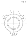
- the pipe socket 4 of the guide sleeve 1 is shown as a single part, which is integrally formed with the mounting flange 5.
- the mounting flange 5 has three evenly distributed recesses for attachment to the outer wall of the transmission housing.
- the radially outer, second axial leg 7 of the pipe socket 4 completely covers the statically stressed second sealing lip 10 radially on the outside and thereby protects it from harmful mechanical influences.
Landscapes
- Engineering & Computer Science (AREA)
- General Engineering & Computer Science (AREA)
- Mechanical Engineering (AREA)
- Mechanical Operated Clutches (AREA)
- Sealing Of Bearings (AREA)
- Sealing With Elastic Sealing Lips (AREA)
- Sealing Devices (AREA)
- Fluid-Damping Devices (AREA)
Abstract
Führungshülse (1) mit integrierter Dichtung (2) für das Kupplungsausrücklager eines Getriebes, umfassend einen eine Eingangswelle (3) des Getriebes umfangsseitig mit radialem Abstand umschließenden Rohrstutzen (4) und einen am Rohrstutzen (4) festgelegten Befestigungsflansch (5), wobei der Rohrstutzen (4) auf der der Außenwand des Getriebes zugewandten Seite einen im wesentlichen Z-förmigen Querschnitt aufweist, wobei der Z-förmige Querschnitt durch einen radial innen liegenden ersten Axialschenkel (6) und einen radial außen liegenden zweiten Axialschenkel (7) gebildet ist und wobei der erste und der zweite Axialschenkel (6, 7) durch einen Radialschenkel (8) miteinander verbunden sind. Die Dichtung (2) weist ein an den Rohrstutzen (4) angepaßtes Z-förmiges Profil auf, wobei die Dichtung (2) auf der der abzudichtenden Eingangswelle (3) zugewandten Seite mit zumindest einer dynamisch beanspruchten ersten Dichtlippe (9) und auf der der Außenwand des Getriebes zugewandten Seite mit zumindest einer axial in Richtung der Außenwand vorstehenden und mit dieser in dichtenden Eingriff bringbaren statisch beanspruchten zweiten Dichtlippe (10) versehen ist. Die erste und die zweite Dichtlippe (9, 10) sind einstückig ineinander übergehend an einem Versteifungsring (11) aus einem nicht kriechenden Werkstoff festgelegt, wobei der Versteifungsring (11) unter radialer Vorspannung in dem ersten Axialschenkel (6) gehalten ist.
Description
Die Erfindung betrifft eine Führungshülse mit integrierter Dichtung für das Kupplungsausrücklager eines Getriebes, umfassend einen eine Eingangswelle des Getriebes umfangsseitig mit radialem Abstand umschließenden Rohrstutzen und einen am Rohrstutzen festgelegten Befestigungsflansch, wobei der Rohrstutzen auf der der Außenwand des Getriebes zugewandten Seite einen im wesentlichen Z-förmigen Querschnitt aufweist, wobei der Z-förmige Querschnitt durch einen radial innen liegenden ersten Axialschenkel und einen radial außen liegenden zweiten Axialschenkel gebildet ist und wobei der erste und der zweite Axialschenkel durch einen Radialschenkel miteinander verbunden sind.The invention relates to a guide sleeve with an integrated seal for the clutch release bearing of a transmission, comprising a pipe socket surrounding an input shaft of the transmission with a radial spacing on the circumference and a fastening flange fixed to the pipe socket, the pipe socket on the side facing the outer wall of the transmission having a substantially Z-shaped shape Cross section, wherein the Z-shaped cross section is formed by a radially inner first axial arm and a radially outer second axial arm and wherein the first and second axial arm are connected to each other by a radial arm.
Eine solche Führungshülse ist aus der EP-0 301 965 bekannt. Die darin gezeigte Führungshülse für das Kupplungsausrücklager eines Kraftfahrzeuggetriebes zeigt einen Befestigungsflansch zur Befestigung der Führungshülse mit der Außenfläche einer Getriebegehäusewand, wobei der Befestigungsflansch in der gleichen Radialebene angeordnet ist, wie ein Rohrabschnitt, der den Dichtungsring aufnimmt. Dabei ist allerdings zu beachten, daß der Dichtungsring an einem sich in radialer Richtung erstreckenden Rohrabschnitt angeordnet ist und dadurch Relaxationserscheinungen des elastomeren Werkstoffs begünstigt werden, was zu Undichtigkeiten im Bereich der dynamischen Abdichtung führen kann.Such a guide sleeve is known from EP-0 301 965. The guide sleeve shown therein for the clutch release bearing of a motor vehicle transmission shows a fastening flange for fastening the guide sleeve to the outer surface of a transmission housing wall, the fastening flange being arranged in the same radial plane as a pipe section which receives the sealing ring. It should be noted, however, that the sealing ring is arranged on a pipe section extending in the radial direction and thus relaxation phenomena of the elastomeric material are promoted, which can lead to leaks in the area of the dynamic seal.
Der Erfindung liegt die Aufgabe zugrunde, einen verbesserte dynamische Abdichtung der Eingangswelle durch eine stabilere Festlegung der Dichtung innerhalb des Rohrstutzens zu bewirken und gleichzeitig die Außenwand des Getriebes während einer langen Gebrauchsdauer statisch abzudichten.The invention has for its object to effect an improved dynamic sealing of the input shaft by a more stable fixing of the seal within the pipe socket and at the same time statically seal the outer wall of the transmission during a long period of use.
Diese Aufgabe wird erfindungsgemäß mit den Merkmalen von Anspruch 1 gelöst. Auf vorteilhafte Ausgestaltungen nehmen die Unteransprüche Bezug.This object is achieved with the features of claim 1. The subclaims refer to advantageous embodiments.
Im Rahmen der vorliegenden Erfindung ist es vorgesehen, daß die Dichtung ein an den Rohrstutzen angepaßtes, Z-förmiges Profil aufweist, das die Dichtung auf der der abzudichtenden Eingangswelle zugewandten Seite mit zumindest einer dynamisch beanspruchten Dichtlippe und auf der der Außenwand des Getriebes zugewandten Seite mit zumindest einer axial in Richtung der Außenwand vorstehenden und mit dieser in dichtenden Eingriff bringbaren statisch beanspruchten zweiten Dichtlippe versehen ist, daß die erste und die zweite Dichtlippe einstückig ineinander übergehend an einem Versteifungsring aus einem nicht kriechenden Werkstoff festgelegt sind und daß der Versteifungsring unter radialer Vorspannung in dem ersten Axialschenkel gehalten ist. Durch das an das Z-förmige Profil des Rohrstutzens angepaßte Profil der Dichtung, wobei die erste und die Zweite Dichtlippe einstückig ineinander übergehend an einem Z-förmigen Versteifungsring aus einem nicht kriechenden Werkstoff, beispielsweise Metall, festgelegt sind und dieser unter radialer Vorspannung von dem ersten Axialschenkel des Rohrstutzens, der bevorzugt ebenfalls aus einem metallischen Werkstoff besteht, umschlossen ist, ergibt sich eine stabile räumliche Zuordnung der Dichtlippen bezogen auf die abzudichtenden Flächen und den Rohrstutzen. Desweiteren ist von Vorteil, daß bei radialen Auslenkbewegungen der abzudichtenden Eingangswelle die Dichtung am Versteifungsring nur auf Druck belastet wird. Gebrauchsdauerverringernde Schub- und Zugspannungen, insbesondere im Bereich der Festlegung am Versteifungsring, können durch die Ausgestaltung der Dichtung und ihrer Anordnung innerhalb des Rohrstutzens zuverlässig vermieden werden. Durch die kompakte Bauform der Dichtung und die relativ steife Zuordnung der ersten und zweiten Dichtlippe am Versteifungsring ist eine exakte Positionierung der Dichtung an den abzudichtenden Flächen gewährleistet.In the context of the present invention it is provided that the seal has a Z-shaped profile which is adapted to the pipe socket and which has the seal on the side facing the input shaft to be sealed with at least one dynamically stressed sealing lip and on the side facing the outer wall of the transmission At least one statically stressed second sealing lip projecting axially in the direction of the outer wall and which can be brought into sealing engagement with it is provided that the first and the second sealing lip are integrally merged into one another on a stiffening ring made of a non-creeping material and that the stiffening ring under radial prestress in the first axial leg is held. Due to the profile of the seal adapted to the Z-shaped profile of the pipe socket, the first and second sealing lips being integrally merged into one another on a Z-shaped stiffening ring made of a non-creeping material, for example metal, and this is under radial prestress from the first Axial leg of the pipe socket, which is preferably also made of a metallic material, is enclosed, there is a stable spatial assignment of the sealing lips in relation to the surfaces to be sealed and the pipe socket. It is also an advantage that in the case of radial deflection movements of the input shaft to be sealed, the seal on the stiffening ring is only loaded under pressure. Shear and tensile stresses reducing service life, in particular in the area of the attachment to the stiffening ring, can be reliably avoided by the design of the seal and its arrangement within the pipe socket. The compact design of the seal and the relatively rigid assignment of the first and second sealing lips on the stiffening ring ensure exact positioning of the seal on the surfaces to be sealed.
Während der bestimmungsgemäßen Verwendung kann berühren der Versteifungsring den Radialschenkel und axialer Vorspannung dichtend berühren. Die axiale Vorspannung wird dadurch erzeugt, daß die statisch beanspruchte Zweite Dichtlippe bei der Montage der Führungshülse an der Abschlußwandung des Getriebes elastisch verformt wird, so daß der Versteifungsring, der auf der der Abschlußwand gegenüberliegenden Seite der zweiten Dichtlippe angeordnet ist, an den Radialschenkel der Kupplungsführungshülse angelegt ist.During the intended use, the stiffening ring can touch the radial leg and the axial preload. The axial preload is generated by the fact that the statically stressed second sealing lip is elastically deformed when the guide sleeve is mounted on the end wall of the transmission, so that the stiffening ring, which is arranged on the side of the second sealing lip opposite the end wall, on the radial leg of the clutch guide sleeve is created.
Eine exakte Zuordnung der Dichtung zu dem Rohrstutzen kann dadurch erzielt werden, daß der Versteifungsring und der Rohrstutzen einander direkt anliegend berühren. Neben dieser Ausgestaltung ist außerdem eine Ausführung denkbar, bei der der Versteifungsring auf der dem Radialschenkel des Rohrstutzens zugewandten Seite in zumindest einem Teilbereich seiner radialen Erstreckung vom Dichtungswerkstoff der zweiten Dichtlippe vollständig umschlossen ist.An exact assignment of the seal to the pipe socket can be achieved in that the stiffening ring and the pipe socket touch each other directly. In addition to this embodiment, an embodiment is also conceivable in which the stiffening ring on the side facing the radial leg of the pipe socket is completely enclosed by the sealing material of the second sealing lip in at least a partial area of its radial extent.
Im Hinblick auf einen größtmöglichen Schutz der zweiten Dichtlippe vor mechanischen, äußeren Einflüssen kann die zweite Dichtlippe während der bestimmungsgemäßen Verwendung zumindest teilweise bevorzugt vollständig von dem zweiten Axialschenkel überdeckt sein, wobei der zweite Axialschenkel im Bereich seiner Stirnfläche die Außenwand des Getriebes zweckmäßig anliegend berührt. Der zweite Axialschenkel bedingt einerseits einen Schutz der zweiten Dichtlippe vor äußeren Einflüssen und andererseits einen Schutz der zweiten Dichtlippe vor übermäßiger Durckbeanspruchung in axialer Richtung. Die Montage der Führungshülse wird dadurch erheblich vereinfacht, daß sie an die Außenwand des Getriebes angeschraubt wird, bis der zweite Axialschenkel mit seiner Stirnfläche an der Außenwand des Getriebes anliegt. Die vor der Montage in axialer Richtung über die Stirnfläche des zweiten Axialschenkels vorstehenden zweite Dichtlippe berührt dann die Außenwand des Getriebes unter einer genau vorher bestimmten axialen Anpressung.With regard to the greatest possible protection of the second sealing lip against mechanical, external influences, the second one can During the intended use, the sealing lip may be at least partially completely covered by the second axial leg, the second axial leg appropriately contacting the outer wall of the transmission in the region of its end face. The second axial limb requires, on the one hand, protection of the second sealing lip from external influences and, on the other hand, protection of the second sealing lip from excessive pressure in the axial direction. The assembly of the guide sleeve is considerably simplified in that it is screwed onto the outer wall of the gear unit until the end face of the second axial leg lies against the outer wall of the gear unit. The second sealing lip protruding axially over the end face of the second axial leg before assembly then touches the outer wall of the transmission under a predetermined axial pressure.
Gemäß einer vorteilhaften Ausgestaltung können der Rohrstutzen und der Befestigungsflansch einstückig ausgebildet sein. Neben einer einfacheren Herstellbarkeit durch weniger Teile, die aneinander montiert werden müssen, ist die Montage vereinfacht.According to an advantageous embodiment, the pipe socket and the fastening flange can be formed in one piece. In addition to being easier to manufacture due to fewer parts that have to be assembled, the assembly is simplified.
Eine verbesserte statische Abdichtung kann dadurch erzielt werden, daß die zweite Dichtlippe mit einer radial benachbarten Zusatzdichtlippe einen Spalt begrenzt, der mit einer Fettfüllung versehen ist.An improved static seal can be achieved in that the second sealing lip with a radially adjacent additional sealing lip delimits a gap which is provided with a grease filling.
Eine besonders stabile und genaue Zuordnung der Dichtung innerhalb des Rohrstutzens kann dadurch erzielt werden, daß das Verhältnis von axialer Ausdehnung der Dichtung zu radialer Ausdehnung 1:1 bis 1:0,25 beträgt. Verkantungserscheinungen bei Verlagerungen der abzudichtenden Eingangswelle sind durch diese Ausgestaltung nicht zu befürchten. Dadurch, daß die radiale Ausdehnung höchstens genau so groß ist, wie die axiale Ausdehnung der Dichtung, bevorzugt allerdings deutlich geringer, ergibt sich eine besonders lange Führung der dynamisch beanspruchten ersten Dichtlippe innerhalb des radial innen liegenden ersten Axialschenkels, so daß herstellungsbedingten Toleranzen des Rohrstutzens keinen negativen Einfluß auf die Gebrauchseigenschaften der Führungshülse haben. Eine besonders große Maßhaltigkeit des ersten Axialschenkels bezogen auf den Radialschenkel ist daher nicht erforderlich, wodurch die Führungshülse einfacher und wirtschaftlich günstig herstellbar ist.A particularly stable and precise assignment of the seal within the pipe socket can be achieved in that the ratio of the axial expansion of the seal to the radial expansion is 1: 1 to 1: 0.25. Signs of tilting when the input shaft to be sealed is displaced are not to be feared by this configuration. Because the radial Expansion is at most as large as the axial expansion of the seal, but preferably significantly less, results in a particularly long guidance of the dynamically stressed first sealing lip within the radially inner first axial leg, so that manufacturing-related tolerances of the pipe socket do not have a negative influence on the usage properties the guide sleeve. A particularly high degree of dimensional accuracy of the first axial leg in relation to the radial leg is therefore not necessary, as a result of which the guide sleeve can be manufactured more simply and economically.
Die dynamisch beanspruchte erste Dichtlippe kann voneinander durchschneidenden Kegelflächen begrenzt sein, wobei die auf der dem abzudichtenden Medium zugewandten Seite angeordnete Kegelfläche einen größeren Winkel mit der Oberfläche der abzudichtenden Eingangswelle einschließt, als die Kegelfläche auf der axial gegenüberliegenden Seite. Diese Ausgestaltung bewirkt eine Rückförderwirkung des abzudichtenden Mediums in Richtung des abzudichtenden Raums und eine ständige Erneuerung des Schmierfilms zwischen der ersten Dichtlippe und der abzudichtenden Welle durch ständige Umwälzung des Schmiermittels. Der dynamisch beanspruchten ersten Dichtlippe kann auf der dem abzudichtenden Raum abgewandten Seite eine Schutzdichtlippe zugeordnet sein, die eine Beaufschlagung der ersten Dichtlippe mit gebrauchsdauerverringernden Schadstoffpartikeln verhindert.The dynamically stressed first sealing lip can be delimited by conical surfaces intersecting one another, the conical surface arranged on the side facing the medium to be sealed enclosing a larger angle with the surface of the input shaft to be sealed than the conical surface on the axially opposite side. This configuration brings about a return conveying effect of the medium to be sealed in the direction of the space to be sealed and a constant renewal of the lubricating film between the first sealing lip and the shaft to be sealed by constant circulation of the lubricant. The dynamically stressed first sealing lip can be assigned a protective sealing lip on the side facing away from the space to be sealed, which prevents the first sealing lip from being exposed to pollutant particles that reduce the service life.
Für die exakte Zuordnung der dynamisch beanspruchten ersten Dichtlippe zwischen dem Rohrstutzen und der abzudichtenden Welle ist es vorgesehen, daß der radiale Abstand zwischen Eingangswelle und Rohrstutzen 0,25 bis 1 mal so groß ist, wie die axiale Ausdehnung der Versteifungsringes auf der dem ersten Axialschenkel gegenüberliegenden Seite. Ein geringer radialer Abstand zwischen der Eingangswelle und dem Rohrstutzen bedingt eine formstabile Ausgestaltung der Dichtung auch bei Verlagerungen der Eingangswelle in axialer Richtung, beispielsweise durch Wärmedehnung hervorgerufen. Die räumliche Zuordnung der dynamisch beanspruchten ersten Dichtlippe verändert ihre Lage im bezug auf die Oberfläche der abzudichtenden Welle nicht, so daß sich stets gleichbleibende Dichtungseigenschaften, beispielsweise ein stets gleichbleibender Rückfördereffekt während der bestimmungsgemäßen Verwendung einstellen.For the exact assignment of the dynamically stressed first sealing lip between the pipe socket and the shaft to be sealed, it is provided that the radial distance between the input shaft and the pipe socket is 0.25 to 1 times as large as the axial extension of the stiffening ring on the first Axial leg opposite side. A small radial distance between the input shaft and the pipe socket requires a dimensionally stable design of the seal even when the input shaft is displaced in the axial direction, for example caused by thermal expansion. The spatial assignment of the dynamically stressed first sealing lip does not change its position with respect to the surface of the shaft to be sealed, so that the sealing properties are always constant, for example a constant return flow effect during the intended use.
Die erfindungsgemäße Führungshülse wird nachfolgend anhand eines Ausführungsbeispiels näher erläutert. Dieses zeigt die zu berücksichtigenden Einzelkomponenten teilweise in schematischer Darstellung.The guide sleeve according to the invention is explained in more detail below using an exemplary embodiment. This shows the individual components to be taken into account, partly in a schematic representation.
In Figur 1 ist ein Ausführungsbeispiel einer Führungshülse mit integrierter Dichtung in quergeschnittener Darstellung gezeigt.In Figure 1, an embodiment of a guide sleeve with an integrated seal is shown in a cross-sectional view.
In Figur 2 ist der Rohrstutzen aus Figur 1 als Einzelteil dargestellt.In Figure 2, the pipe socket from Figure 1 is shown as a single part.
In Figur 1 ist eine Führungshülse 1 mit integrierter Dichtung 2 dargestellt, die im Bereich des Kupplungsausrücklagers eines Getriebes, beispielsweise für Kraftfahrzeuge, zur Anwendung gelangt. Die Führungshülse 1 umfaßt einen Rohrstutzen 4, der eine Eingangswelle 3 des Getriebes umfangsseitig mit radialem Abstand umschließt. Das hier nicht dargestellte Getriebe ist auf der dem abzudichtenden Medium zugewandten Seite 16 an die Führungshülse 1 angeflanscht. Der Rohrstutzen 4 und der Befestigungsflansch 5 sind einstückig ineinander übergehend ausgebildet und bestehen in diesem Ausführungsbeispiel aus einem tiefgezogenen Blech. Der Rohrstutzen 4 umfaßt einen radial innen liegenden ersten Axialschenkel 6 und einen radial außen liegenden zweiten Axialschenkel 7, die über einen Radialschenkel 8 miteinander verbunden sind. Der radial innenliegende erste Axialschenkel 6 umschließt den Versteifungsring 11 unter radialer Vorspannung, wobei der Versteifungsring 11 im Bereich seiner axialen und im Bereich seiner radialen Erstreckung den Rohrstutzen 4 anliegend berührt. Die Dichtung 2 wird durch eine reibschlüssige Verbindung zwischen dem Versteifungsring 11 und dem ersten Axialschenkel 6 gehalten. Die Dichtung 2 umfaßt in diesem Ausführungsbeispiel eine dynamisch beanspruchte erste Dichtlippe 9 die die abzudichtende Eingangswelle 3 dynamisch abdichtet. Auf der der Außenwand des Getriebes zugewandten Seite sind zwei statisch beanspruchte zweite Dichtlippen 10, 12 angeordnete, die einander mit radialem Abstand benachbart zugeordnet sind, wobei der durch den radialen Abstand gebildete Spalt 13 zwischen der zweiten Dichtlippe 10 und der Zusatzdichtlippe 12 mit Fett gefüllt ist. Die Herstellung der beanspruchten Führungshülse 1 ist besonders einfach, da sie aus nur zwei aneinander festzulegenden Teilen besteht. Der Rohrstutzen 4 mit dem einstückig ausgebildeten Befestigungsflansch 5 bildet im Bereich des ersten Axialschenkels 6 die Aufnahme für die Dichtung 2, bei der die erste Dichtlippe 9 und die zweite Dichtlippe 10 einstückig ineinander übergehend an einem Versteifungsring 11 festgelegt sind. Durch die vorteilhaften geometrischen Abmessungen der Dichtung 2, deren Verhältnis von axialer Ausdehnung zu radialer Ausdehnung 1:1 bis 1.0,25, bevorzugt 1:0,75 bis 1:0,5 beträgt, ist eine exakte und während der bestimmungsgemäßen Verwendung stets gleichbleibende Zuordnung zwischen den einzelnen Teilen der Führungshülse 1 bedingt. Herstellungsbedingte Toleranzen des Rohrstutzens 4 vermögen die guten Gebrauchseigenschaften der Führungshülse nicht zu beeinträchtigen. Der zweite Axialschenkel 7 überdeckt die statische beanspruchte zweite Dichtlippe in diesem Ausführungsbeispiel vollständig, so daß mechanische Beschädigungen der zweiten Dichtlippe 10 zuverlässig vermieden werden können. Zur Begrenzung der elastischen Verformung der zweiten Dichtlippe 10 während der Montage an der Außenwand des Getriebes ist der zweite Axialschenkel 7 derart angeordnet, daß er sich bei einer vorher bestimmten elastischem Vorspannung der zweiten Dichtlippe 10 an die Außenwandung des Getriebes anlegt und dadurch eine noch größere Verformung, möglicherweise eine Überbeanspruchung der zweiten Dichtlippe 10, verhindert.1 shows a guide sleeve 1 with an integrated
Die axiale Ausdehnung der Dichtung 2 ist in diesem Ausführungsbeispiel doppelt so groß, wie die radiale Ausdehnung.In this exemplary embodiment, the axial extent of the
In Figur 2 ist der Rohrstutzen 4 der Führungshülse 1 als Einzelteil gezeigt, der einstückig mit dem Befestigungsflansch 5 ausgebildet ist. Der Befestigungsflansch 5 weist drei gleichmäßig in Umfangsrichtung verteilte Ausnehmungen zur Befestigung an der Außenwand des Getriebegehäuses auf. In dieser Darstellung ist zu erkennen, daß der radial außen liegende, zweite Axialschenkel 7 des Rohrstutzens 4 die statisch beanspruchte zweite Dichtlippe 10 radial außenseitig vollständig überdeckt und sie dadurch vor schädlichen mechanischen Einflüssen schützt.In Figure 2, the
Claims (9)
Applications Claiming Priority (2)
| Application Number | Priority Date | Filing Date | Title |
|---|---|---|---|
| DE4224179A DE4224179C1 (en) | 1992-07-22 | 1992-07-22 | Guide sleeve with integrated seal for a clutch release bearing of a transmission |
| DE4224179 | 1992-07-22 |
Publications (3)
| Publication Number | Publication Date |
|---|---|
| EP0579869A2 true EP0579869A2 (en) | 1994-01-26 |
| EP0579869A3 EP0579869A3 (en) | 1994-08-03 |
| EP0579869B1 EP0579869B1 (en) | 1996-09-04 |
Family
ID=6463835
Family Applications (1)
| Application Number | Title | Priority Date | Filing Date |
|---|---|---|---|
| EP92121544A Expired - Lifetime EP0579869B1 (en) | 1992-07-22 | 1992-12-18 | Guide-tube with integrated sealing means for a clutch release bearing in a transmission |
Country Status (7)
| Country | Link |
|---|---|
| US (1) | US5368397A (en) |
| EP (1) | EP0579869B1 (en) |
| JP (1) | JPH06185540A (en) |
| AT (1) | ATE142315T1 (en) |
| BR (1) | BR9302713A (en) |
| DE (2) | DE4224179C1 (en) |
| ES (1) | ES2092006T3 (en) |
Cited By (2)
| Publication number | Priority date | Publication date | Assignee | Title |
|---|---|---|---|---|
| EP0866247A2 (en) | 1997-03-19 | 1998-09-23 | Firma Carl Freudenberg | Radial shaft seal |
| WO2021151983A1 (en) * | 2020-01-30 | 2021-08-05 | Ngi A/S | Bearing house design |
Families Citing this family (14)
| Publication number | Priority date | Publication date | Assignee | Title |
|---|---|---|---|---|
| DE4327929A1 (en) * | 1993-08-19 | 1995-02-23 | Bruss Dichtungstechnik | Sealing for the guide sleeve of the release bearing of a clutch |
| US5498085A (en) * | 1994-12-15 | 1996-03-12 | Chrysler Corporation | Shaft sealing systems |
| JP3305591B2 (en) * | 1996-09-26 | 2002-07-22 | 富士機工株式会社 | Bearing for steering column |
| US6177744B1 (en) * | 1998-03-17 | 2001-01-23 | Reliance Electric Technologies, Llc | Seal arrangement for an electric motor |
| JP4957937B2 (en) * | 2001-07-27 | 2012-06-20 | Nok株式会社 | Sealing device |
| US7419305B2 (en) * | 2001-08-24 | 2008-09-02 | Reliance Electric Technologies Llc | Sealing system for bearing assembly |
| DE10325254C5 (en) | 2003-06-03 | 2011-03-31 | Carl Freudenberg Kg | Mounting protection ring |
| US7226212B2 (en) * | 2004-03-01 | 2007-06-05 | Minebea Co., Ltd. | Shield and sealing method for a hydrodynamic bearing |
| US7461907B2 (en) * | 2005-07-18 | 2008-12-09 | Bendix Spicer Foundation Brake Llc | Rod/seal bearing arrangement utilizing locking fingers |
| EP2100047B1 (en) * | 2006-12-06 | 2012-08-15 | Husqvarna Aktiebolag | A crankshaft bearing arrangement of a combustion engine |
| FR2986598B1 (en) * | 2012-02-03 | 2015-03-27 | Freudenberg Carl Kg | SEAL |
| FR3020421B1 (en) * | 2014-04-24 | 2016-12-30 | Skf Ab | BEARING BEARING, IN PARTICULAR FOR A CLUTCH STOP DEVICE |
| CN106321846A (en) * | 2016-11-10 | 2017-01-11 | 昆山健博密封件科技有限公司 | Double framework oil seal part |
| CN109882507B (en) * | 2017-12-06 | 2020-10-27 | 舍弗勒技术股份两合公司 | Bearing arrangement for a dual clutch transmission |
Family Cites Families (12)
| Publication number | Priority date | Publication date | Assignee | Title |
|---|---|---|---|---|
| DE1867721U (en) * | 1962-12-20 | 1963-02-21 | Elektro Motoren Feinbauwerk Gr | HAT CUFF SHAFT SEAL. |
| DE7509224U (en) * | 1975-03-22 | 1975-07-17 | Skf Kugellagerfabriken Gmbh | GUIDE SLEEVE |
| JPS57111683A (en) * | 1980-12-27 | 1982-07-12 | Fujitsu Ltd | Document storage device |
| JPS5884513A (en) * | 1981-11-13 | 1983-05-20 | Nippon Gakki Seizo Kk | Gain controlling amplifier |
| JPS61209121A (en) * | 1985-02-05 | 1986-09-17 | Sanyo Kokusaku Pulp Co Ltd | Manufacture of thermoplastic resin sheet containing metallic layer therein |
| FR2611833B1 (en) * | 1987-02-24 | 1989-06-30 | Hutchinson | IMPROVEMENTS ON GUIDE TUBES ARRANGED BETWEEN THE GEARBOX AND THE CLUTCH OF A VEHICLE AND IN JOINTS EQUIPPED WITH SUCH GUIDE TUBES |
| FR2618864B1 (en) * | 1987-07-28 | 1991-06-21 | Procal | GUIDE TUBE FOR AUTOMOBILE GEARBOX CLUTCH |
| FR2629539B1 (en) * | 1988-04-05 | 1993-04-16 | Procal | GUIDE TUBE WITH INTEGRATED SEAL FOR AUTOMOBILE GEARBOX RELEASE STOP |
| DE3816890A1 (en) * | 1988-05-18 | 1989-11-30 | Schaeffler Waelzlager Kg | RELEASE BEARING DEVICE FOR A PRESSED MOTOR VEHICLE CLUTCH |
| US4960193A (en) * | 1989-01-27 | 1990-10-02 | Ina Bearing Company, Inc. | Concentric slave cylinder |
| FR2656395B1 (en) * | 1989-12-22 | 1994-12-30 | Procal | GUIDE TUBE WITH BUILT-IN SEAL FOR MOTOR VEHICLE GEARBOX CLUTCH. |
| FR2682441B1 (en) * | 1991-10-15 | 1993-12-10 | Procal | GUIDE TUBE WITH BUILT-IN SEAL FOR MOTOR VEHICLE GEARBOX CLUTCH. |
-
1992
- 1992-07-22 DE DE4224179A patent/DE4224179C1/en not_active Expired - Lifetime
- 1992-12-18 EP EP92121544A patent/EP0579869B1/en not_active Expired - Lifetime
- 1992-12-18 AT AT92121544T patent/ATE142315T1/en not_active IP Right Cessation
- 1992-12-18 DE DE59207065T patent/DE59207065D1/en not_active Expired - Fee Related
- 1992-12-18 ES ES92121544T patent/ES2092006T3/en not_active Expired - Lifetime
-
1993
- 1993-06-30 BR BR9302713A patent/BR9302713A/en not_active IP Right Cessation
- 1993-07-21 JP JP5180086A patent/JPH06185540A/en active Pending
- 1993-07-22 US US08/096,079 patent/US5368397A/en not_active Expired - Lifetime
Cited By (5)
| Publication number | Priority date | Publication date | Assignee | Title |
|---|---|---|---|---|
| EP0866247A2 (en) | 1997-03-19 | 1998-09-23 | Firma Carl Freudenberg | Radial shaft seal |
| US6062571A (en) * | 1997-03-19 | 2000-05-16 | Firma Carl Freudenberg | Radial shaft sealing ring |
| WO2021151983A1 (en) * | 2020-01-30 | 2021-08-05 | Ngi A/S | Bearing house design |
| CN115023559A (en) * | 2020-01-30 | 2022-09-06 | Ngi股份公司 | Bearing shell design |
| US12385528B2 (en) | 2020-01-30 | 2025-08-12 | Ngi A/S | Bearing housing |
Also Published As
| Publication number | Publication date |
|---|---|
| JPH06185540A (en) | 1994-07-05 |
| EP0579869B1 (en) | 1996-09-04 |
| BR9302713A (en) | 1994-02-01 |
| DE59207065D1 (en) | 1996-10-10 |
| ES2092006T3 (en) | 1996-11-16 |
| US5368397A (en) | 1994-11-29 |
| ATE142315T1 (en) | 1996-09-15 |
| EP0579869A3 (en) | 1994-08-03 |
| DE4224179C1 (en) | 1993-11-11 |
Similar Documents
| Publication | Publication Date | Title |
|---|---|---|
| EP0562160B1 (en) | Sealing arrangement | |
| DE4224179C1 (en) | Guide sleeve with integrated seal for a clutch release bearing of a transmission | |
| EP0557579B1 (en) | Sealing arrangement | |
| DE4438947C2 (en) | Sealing arrangement | |
| EP0431263A1 (en) | Seal unit | |
| DE10024026A1 (en) | Sealing sleeve, especially for installation spaces with small dimensions | |
| DE3524461C2 (en) | ||
| EP0774568A1 (en) | Sealing arrangement | |
| EP0596196B1 (en) | Sealing arrangement | |
| EP0418671A1 (en) | Rubber-sleeved spring with hydraulic damping for automotive vehicle mountings | |
| EP0732529A1 (en) | Sealing ring | |
| DE19728605A1 (en) | Rod or piston seal | |
| DE8536143U1 (en) | Arrangement for sealing bearings, in particular spherical plain bearings with an outer ring composed of two half-shells | |
| DE8236692U1 (en) | GASKET ARRANGEMENT FOR THE ARTICULATED CONNECTION OF TWO PIPELINES, IN PARTICULAR HEATING EXHAUST PIPES | |
| DE19648602C2 (en) | Sealing arrangement | |
| DE4225556C2 (en) | Rod guide supported between radially inward projections of a cylinder surface | |
| DE4209320C2 (en) | Bearing and sealing unit | |
| DE102018104123B3 (en) | Seal, seal assembly and their use | |
| DE19726433C2 (en) | Sealing arrangement | |
| EP0524133A1 (en) | Axle sealing | |
| DE7834928U1 (en) | CLUTCH RELEASE, ESPECIALLY FOR MOTOR VEHICLE CLUTCHES | |
| DE3317767A1 (en) | Seal | |
| EP1055849B1 (en) | Sealing assembly for pressurized enclosures | |
| EP0565771A1 (en) | Hub seal | |
| EP1818579B1 (en) | Scraping arrangement |
Legal Events
| Date | Code | Title | Description |
|---|---|---|---|
| PUAI | Public reference made under article 153(3) epc to a published international application that has entered the european phase |
Free format text: ORIGINAL CODE: 0009012 |
|
| AK | Designated contracting states |
Kind code of ref document: A2 Designated state(s): AT DE ES FR GB IT |
|
| PUAL | Search report despatched |
Free format text: ORIGINAL CODE: 0009013 |
|
| RAP3 | Party data changed (applicant data changed or rights of an application transferred) |
Owner name: FIRMA CARL FREUDENBERG |
|
| AK | Designated contracting states |
Kind code of ref document: A3 Designated state(s): AT DE ES FR GB IT |
|
| 17P | Request for examination filed |
Effective date: 19940707 |
|
| 17Q | First examination report despatched |
Effective date: 19950428 |
|
| GRAG | Despatch of communication of intention to grant |
Free format text: ORIGINAL CODE: EPIDOS AGRA |
|
| GRAH | Despatch of communication of intention to grant a patent |
Free format text: ORIGINAL CODE: EPIDOS IGRA |
|
| GRAH | Despatch of communication of intention to grant a patent |
Free format text: ORIGINAL CODE: EPIDOS IGRA |
|
| GRAA | (expected) grant |
Free format text: ORIGINAL CODE: 0009210 |
|
| AK | Designated contracting states |
Kind code of ref document: B1 Designated state(s): AT DE ES FR GB IT |
|
| REF | Corresponds to: |
Ref document number: 142315 Country of ref document: AT Date of ref document: 19960915 Kind code of ref document: T |
|
| ITF | It: translation for a ep patent filed | ||
| GBT | Gb: translation of ep patent filed (gb section 77(6)(a)/1977) |
Effective date: 19960917 |
|
| REF | Corresponds to: |
Ref document number: 59207065 Country of ref document: DE Date of ref document: 19961010 |
|
| ET | Fr: translation filed | ||
| REG | Reference to a national code |
Ref country code: ES Ref legal event code: FG2A Ref document number: 2092006 Country of ref document: ES Kind code of ref document: T3 |
|
| PLBE | No opposition filed within time limit |
Free format text: ORIGINAL CODE: 0009261 |
|
| STAA | Information on the status of an ep patent application or granted ep patent |
Free format text: STATUS: NO OPPOSITION FILED WITHIN TIME LIMIT |
|
| 26N | No opposition filed | ||
| REG | Reference to a national code |
Ref country code: GB Ref legal event code: IF02 |
|
| PGFP | Annual fee paid to national office [announced via postgrant information from national office to epo] |
Ref country code: GB Payment date: 20031124 Year of fee payment: 12 |
|
| PGFP | Annual fee paid to national office [announced via postgrant information from national office to epo] |
Ref country code: DE Payment date: 20031127 Year of fee payment: 12 |
|
| PGFP | Annual fee paid to national office [announced via postgrant information from national office to epo] |
Ref country code: ES Payment date: 20031209 Year of fee payment: 12 |
|
| PGFP | Annual fee paid to national office [announced via postgrant information from national office to epo] |
Ref country code: FR Payment date: 20031217 Year of fee payment: 12 |
|
| PGFP | Annual fee paid to national office [announced via postgrant information from national office to epo] |
Ref country code: AT Payment date: 20031219 Year of fee payment: 12 |
|
| PG25 | Lapsed in a contracting state [announced via postgrant information from national office to epo] |
Ref country code: GB Free format text: LAPSE BECAUSE OF NON-PAYMENT OF DUE FEES Effective date: 20041218 Ref country code: AT Free format text: LAPSE BECAUSE OF NON-PAYMENT OF DUE FEES Effective date: 20041218 |
|
| PG25 | Lapsed in a contracting state [announced via postgrant information from national office to epo] |
Ref country code: ES Free format text: LAPSE BECAUSE OF NON-PAYMENT OF DUE FEES Effective date: 20041220 |
|
| PG25 | Lapsed in a contracting state [announced via postgrant information from national office to epo] |
Ref country code: DE Free format text: LAPSE BECAUSE OF NON-PAYMENT OF DUE FEES Effective date: 20050701 |
|
| GBPC | Gb: european patent ceased through non-payment of renewal fee |
Effective date: 20041218 |
|
| PG25 | Lapsed in a contracting state [announced via postgrant information from national office to epo] |
Ref country code: FR Free format text: LAPSE BECAUSE OF NON-PAYMENT OF DUE FEES Effective date: 20050831 |
|
| AK | Designated contracting states |
Kind code of ref document: A1 Designated state(s): AT BE BG CH CY CZ DE DK EE ES FI FR GB GR HU IE IT LI LU MC NL PL PT RO SE SI SK TR |
|
| AX | Request for extension of the european patent |
Extension state: AL LT LV MK |
|
| REG | Reference to a national code |
Ref country code: FR Ref legal event code: ST |
|
| DA1 | Application published (deleted) | ||
| PG25 | Lapsed in a contracting state [announced via postgrant information from national office to epo] |
Ref country code: IT Free format text: LAPSE BECAUSE OF NON-PAYMENT OF DUE FEES;WARNING: LAPSES OF ITALIAN PATENTS WITH EFFECTIVE DATE BEFORE 2007 MAY HAVE OCCURRED AT ANY TIME BEFORE 2007. THE CORRECT EFFECTIVE DATE MAY BE DIFFERENT FROM THE ONE RECORDED. Effective date: 20051218 |
|
| REG | Reference to a national code |
Ref country code: ES Ref legal event code: FD2A Effective date: 20041220 |