EP0577451A1 - Vorrichtung zum Kontrollieren der pneumatischen Einspritzung eines Gemisches für eine Zweitaktbrennkraftmaschine und ihre Verwendung - Google Patents
Vorrichtung zum Kontrollieren der pneumatischen Einspritzung eines Gemisches für eine Zweitaktbrennkraftmaschine und ihre Verwendung Download PDFInfo
- Publication number
- EP0577451A1 EP0577451A1 EP93401502A EP93401502A EP0577451A1 EP 0577451 A1 EP0577451 A1 EP 0577451A1 EP 93401502 A EP93401502 A EP 93401502A EP 93401502 A EP93401502 A EP 93401502A EP 0577451 A1 EP0577451 A1 EP 0577451A1
- Authority
- EP
- European Patent Office
- Prior art keywords
- pipe
- selective
- injection
- engine
- fuel
- Prior art date
- Legal status (The legal status is an assumption and is not a legal conclusion. Google has not performed a legal analysis and makes no representation as to the accuracy of the status listed.)
- Granted
Links
- 238000002347 injection Methods 0.000 title claims abstract description 47
- 239000007924 injection Substances 0.000 title claims abstract description 47
- 238000002485 combustion reaction Methods 0.000 title claims abstract description 28
- 239000000203 mixture Substances 0.000 title claims abstract description 20
- 239000000446 fuel Substances 0.000 claims abstract description 47
- 238000011144 upstream manufacturing Methods 0.000 claims abstract description 18
- 230000006835 compression Effects 0.000 claims description 5
- 238000007906 compression Methods 0.000 claims description 5
- 238000005507 spraying Methods 0.000 claims description 5
- 238000010408 sweeping Methods 0.000 claims description 4
- 238000010926 purge Methods 0.000 claims 1
- 238000004891 communication Methods 0.000 abstract description 6
- 239000007789 gas Substances 0.000 description 27
- 230000000694 effects Effects 0.000 description 7
- 239000007921 spray Substances 0.000 description 5
- 230000035515 penetration Effects 0.000 description 4
- 239000000243 solution Substances 0.000 description 4
- 230000001276 controlling effect Effects 0.000 description 3
- 230000007423 decrease Effects 0.000 description 2
- 230000001627 detrimental effect Effects 0.000 description 2
- 230000002349 favourable effect Effects 0.000 description 2
- 210000000056 organ Anatomy 0.000 description 2
- 238000013517 stratification Methods 0.000 description 2
- 229920000049 Carbon (fiber) Polymers 0.000 description 1
- 230000001133 acceleration Effects 0.000 description 1
- 238000007792 addition Methods 0.000 description 1
- 238000000889 atomisation Methods 0.000 description 1
- 230000033228 biological regulation Effects 0.000 description 1
- 230000000903 blocking effect Effects 0.000 description 1
- 239000004917 carbon fiber Substances 0.000 description 1
- 239000002131 composite material Substances 0.000 description 1
- 238000010276 construction Methods 0.000 description 1
- 238000006073 displacement reaction Methods 0.000 description 1
- 239000011152 fibreglass Substances 0.000 description 1
- 239000003365 glass fiber Substances 0.000 description 1
- 239000007788 liquid Substances 0.000 description 1
- 238000012986 modification Methods 0.000 description 1
- 230000004048 modification Effects 0.000 description 1
- 230000001105 regulatory effect Effects 0.000 description 1
- 238000007789 sealing Methods 0.000 description 1
Images

Classifications
-
- F—MECHANICAL ENGINEERING; LIGHTING; HEATING; WEAPONS; BLASTING
- F02—COMBUSTION ENGINES; HOT-GAS OR COMBUSTION-PRODUCT ENGINE PLANTS
- F02M—SUPPLYING COMBUSTION ENGINES IN GENERAL WITH COMBUSTIBLE MIXTURES OR CONSTITUENTS THEREOF
- F02M69/00—Low-pressure fuel-injection apparatus ; Apparatus with both continuous and intermittent injection; Apparatus injecting different types of fuel
- F02M69/08—Low-pressure fuel-injection apparatus ; Apparatus with both continuous and intermittent injection; Apparatus injecting different types of fuel characterised by the fuel being carried by compressed air into main stream of combustion-air
-
- F—MECHANICAL ENGINEERING; LIGHTING; HEATING; WEAPONS; BLASTING
- F02—COMBUSTION ENGINES; HOT-GAS OR COMBUSTION-PRODUCT ENGINE PLANTS
- F02B—INTERNAL-COMBUSTION PISTON ENGINES; COMBUSTION ENGINES IN GENERAL
- F02B25/00—Engines characterised by using fresh charge for scavenging cylinders
- F02B25/14—Engines characterised by using fresh charge for scavenging cylinders using reverse-flow scavenging, e.g. with both outlet and inlet ports arranged near bottom of piston stroke
- F02B25/145—Engines characterised by using fresh charge for scavenging cylinders using reverse-flow scavenging, e.g. with both outlet and inlet ports arranged near bottom of piston stroke with intake and exhaust valves exclusively in the cylinder head
-
- F—MECHANICAL ENGINEERING; LIGHTING; HEATING; WEAPONS; BLASTING
- F02—COMBUSTION ENGINES; HOT-GAS OR COMBUSTION-PRODUCT ENGINE PLANTS
- F02D—CONTROLLING COMBUSTION ENGINES
- F02D9/00—Controlling engines by throttling air or fuel-and-air induction conduits or exhaust conduits
- F02D9/02—Controlling engines by throttling air or fuel-and-air induction conduits or exhaust conduits concerning induction conduits
-
- F—MECHANICAL ENGINEERING; LIGHTING; HEATING; WEAPONS; BLASTING
- F02—COMBUSTION ENGINES; HOT-GAS OR COMBUSTION-PRODUCT ENGINE PLANTS
- F02M—SUPPLYING COMBUSTION ENGINES IN GENERAL WITH COMBUSTIBLE MIXTURES OR CONSTITUENTS THEREOF
- F02M69/00—Low-pressure fuel-injection apparatus ; Apparatus with both continuous and intermittent injection; Apparatus injecting different types of fuel
- F02M69/10—Low-pressure fuel-injection apparatus ; Apparatus with both continuous and intermittent injection; Apparatus injecting different types of fuel peculiar to scavenged two-stroke engines, e.g. injecting into crankcase-pump chamber
-
- F—MECHANICAL ENGINEERING; LIGHTING; HEATING; WEAPONS; BLASTING
- F02—COMBUSTION ENGINES; HOT-GAS OR COMBUSTION-PRODUCT ENGINE PLANTS
- F02B—INTERNAL-COMBUSTION PISTON ENGINES; COMBUSTION ENGINES IN GENERAL
- F02B75/00—Other engines
- F02B75/02—Engines characterised by their cycles, e.g. six-stroke
- F02B2075/022—Engines characterised by their cycles, e.g. six-stroke having less than six strokes per cycle
- F02B2075/025—Engines characterised by their cycles, e.g. six-stroke having less than six strokes per cycle two
-
- Y—GENERAL TAGGING OF NEW TECHNOLOGICAL DEVELOPMENTS; GENERAL TAGGING OF CROSS-SECTIONAL TECHNOLOGIES SPANNING OVER SEVERAL SECTIONS OF THE IPC; TECHNICAL SUBJECTS COVERED BY FORMER USPC CROSS-REFERENCE ART COLLECTIONS [XRACs] AND DIGESTS
- Y02—TECHNOLOGIES OR APPLICATIONS FOR MITIGATION OR ADAPTATION AGAINST CLIMATE CHANGE
- Y02T—CLIMATE CHANGE MITIGATION TECHNOLOGIES RELATED TO TRANSPORTATION
- Y02T10/00—Road transport of goods or passengers
- Y02T10/10—Internal combustion engine [ICE] based vehicles
- Y02T10/12—Improving ICE efficiencies
Definitions
- the present invention relates to the pneumatic injection of a fuel mixture into a combustion chamber of a two-stroke internal combustion engine.
- the device according to the invention allows control of the flow rate and the pressure of the pressurized air used to pneumatically spray the fuel inside the combustion chamber.
- the quality of combustion will in particular be improved in terms of the conditions of stratification of the gases in the combustion chamber, at low speeds and low loads.
- the present invention makes it possible to adapt the geometry of the pneumatic fuel injection jet, as well as its distribution in space and in time, this in order to optimize its penetration and its mixing with the gases already contained in the combustion of the engine.
- the pneumatic injection system can comprise a pipe opening into the combustion chamber, intended to convey a gas generally under pressure used to spray the fuel.
- This can be brought into the pipeline via a metering system which preferably opens near the end of the pipeline open to the combustion chamber.
- An organ intermittent shutter such as a valve, generally located at the point where the aforementioned pipe opens, authorizes as soon as it is opened, a spraying of the fuel into the combustion chamber thanks to the compressed gas used.
- the patents FR-2,575,521 and FR-2,575,522 show injectors of this type.
- the pressure source used in these examples can come, as illustrated by French patent FR-2,575,523, totally or partially from the pump housing of the cylinder in which the injection takes place or from another cylinder whose offset is used. angular to modify the injection pressure.
- French patent FR-B1-2,592,436 recommends placing a non-return valve on the pressure gas supply pipe so that part of it constitutes a storage capacity for pressurized gas.
- the pneumatic injection system is adjusted to obtain optimum spraying at high loads and at high speeds, less performance may be achieved at lower speeds.
- the opening law of the controlled system is optimized to obtain the spraying quality and the penetration required at high loads and high speeds, if the same level of compressed air pressure is maintained for lower speeds , the introduction of the compressed air-fuel mixture can be too fast, for example driving the fuel too quickly towards the exhaust port.
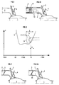
- FIG. 2 shows pressure curves as a function of the crankshaft angle.
- Curve C represents the evolution of the pressure in the cylinder while curves A and B respectively show the compressed air pressure (in the supply line) at high speed and at low speed.
- the duration of injection I is situated substantially around the exhaust closure FE.
- OE designates the exhaust opening, TDC and TDC, respectively the top dead center and the bottom dead center.
- the device according to the invention therefore makes it possible in particular to avoid the problem associated with too rapid and / or too sudden introduction of fuel mixture into the combustion chamber.
- the device according to the invention makes it possible to approximate the curve D defined in dotted lines in FIG. 2, which shows the evolution of the pressure at low speed. During injection I, this pressure is never lower than the cylinder pressure, in other words no "backflow" phenomenon exists in this ideal case.
- Constant and continuous spraying can therefore be carried out.
- the penetration of the fuel mixture into the cylinder is slowed down, which makes it possible under engine operating conditions where a lot of residual burnt gas is present in the cylinder (two-stroke engines under low load conditions, for example) to avoid maximum the mixture between these residual burnt gases and the injected fuel mixture.
- a stratification between the fuel mixture and the residual gases can thus be obtained, which is very favorable for a good course of combustion.
- the injection control device comprises a compressed gas supply pipe which can be placed in communication with the combustion chamber of a cylinder by means of a shutter member. intermittent and a fuel metering device opening into said pipe.
- the device further comprises a selective shutter member disposed in said pipe upstream of said intermittent shutter member and said fuel injection device, and intended to control the fuel mixture conveyed in said pipe and used for pneumatic injection, depending on the operating conditions of said engine.
- the pressurized gas can come from a pump housing or from a pressure source external to the cylinder in question.
- the intermittent shutter member can be a valve.
- this member can be a rotary plug.
- the selective shutter member can be a butterfly valve, or a rotating plug.
- the selective closure member may consist of at least one stop associated with at least one leaf spring, of fiberglass type or the like, on a support, the assembly forming check valve.
- the selective shutter member can consist of an element providing a restriction of the section of said pipe, over a variable length depending on the operating conditions of the engine.
- the device according to the invention may further comprise a conduit for bypassing said supply pipe, said pipe, of diameter smaller than the pipe, being located on either side of the selective closure member and allowing the minimum quantity of air necessary for pneumatic injection to be conveyed under high pressure.
- the bypass duct can be equipped with a flow restriction member.
- the fuel injection device can open out in the part of said branch closest to said first obturation member.
- At least one transfer channel intended to inject sweeping air from the pump housing into said cylinder can be equipped with a flow restriction member, so that a modulation between the air flow injected for sweeping via said transfer channel and the air flow for pneumatic fuel injection can be carried out.
- FIG. 3 schematically shows a combustion chamber 1 into which there opens a pipe 2 for supplying compressed gas which can be placed in communication with the combustion chamber by means of an intermittent shutter member 3 such as a valve.
- an intermittent shutter member 3 such as a valve.
- a rotary plug or any other intermittent shutter member, known per se, can of course be used. The movement of this member can be controlled in a known manner by conventional or other control elements.
- a fuel metering device symbolized here by the arrow 4 makes it possible to introduce liquid fuel into the line 2, preferably near the end of the line 2 opening into the combustion chamber 1.
- a selective shutter member 5 is placed in the line 2 upstream of both the fuel metering device 4 and the intermittent shutter member 3.
- this member is a butterfly valve, while according to Figure 4 a rotary element of the plug type is chosen.
- Other solutions such as diaphragms making it possible to perform the same function, can of course be used without departing from the scope of the present invention.
- the member 5, controlled independently of the member 3 by any means known per se, makes it possible to close more or less the passage section of the pipe 2 as a function of the moment of the cycle, of the load, of the speed ... or other parameters related to engine operation.
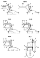
- another solution may consist in placing a non-return valve 55 on the shutter member 5 itself, of the butterfly type.
- a non-return valve 55 on the shutter member 5 itself, of the butterfly type.
- FIG. 5 shows another embodiment of the invention according to which the selective shutter member 5 consists of non-return valves.
- the blades 51 (Figs 5A, 5B) act as springs and open according to the variation of upstream / downstream pressure of the valves. They therefore cause a pressure drop which, moreover, is variable according to this pressure variation.
- This solution also has the advantage of avoiding the return of gas from the combustion chamber upstream of the selective shutter member 4.
- the leaf springs 51 can be metallic or consist of a composite based on glass fibers or carbon fibers ...
- the assembly of the blades 51 and their stops 52 is movable in rotation about an axis perpendicular to the axis of the pipe 2.
- This arrangement makes it possible to combine the check valve effect -return to the closed position with a direct flow control effect depending on the opening.
- a support element 53 can constitute a stop in the center of the pipe 2 in order to ensure good sealing when the blades 51 are in the maximum closed position (FIG. 5A).
- a linkage or any other means may rotate the assembly 51, 52 blade-stop until for example in a housing 54 formed in the pipe, in order '' offer a maximum passage section for pressurized gas.
- FIGS. 6A and 6B the restriction and the pressure drop are obtained by a conduit 60 of reduced cross section relative to the pipe 2.
- this conduit 60 preferably has a variable length, the variation in length, thus making it possible to control the pressure drop and optimize it for each engine operating condition.
- FIG. 6A shows the conduit 60 with a minimum length, hence a low pressure drop
- FIG. 6B illustrates a conduit 60 in the position of maximum elongation.
- the conduit 60 may for example consist of a bellows capable of elongating under the effect of a pressure variation.
- the small conduit 70 calibrated at the minimum flow rate corresponding to what is required by the motor.
- the small conduit 70 consists of a bypass around the member 5 for selective closure.
- precise control of the minimum quantity of air under pressure can simultaneously be achieved, via the bypass 70.
- valve 72 as shown in FIG. 7B can also be placed in the bypass duct 70.
- the fuel metering device 4 may advantageously be placed just downstream of said conduit 70.
- the compressed gas passing through the pipe 70 can be cleverly used to help pre-atomize the fuel upstream of the valve 3.
- some fuel metering devices 4 are designed in such a way that they can use the compressed gas for mixing with the fuel as soon as they leave the injector. This is the case for example of the so-called "air mantle" injectors.
- These injectors are means for continuously or sequentially metering the fuel, which have the particularity of being able to be supplied with compressed air on the periphery of the nose of the fuel injection.
- the pump housing is generally used to supply the source of compressed air necessary for pneumatic injection.
- all the devices described above remain valid, but they can additionally be combined with other means for controlling pneumatic injection.
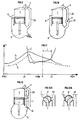
- FIG. 8 thus shows a particular case where the compressed air intended for pneumatic injection comes from the pump housing 8 via a connecting pipe 28. It can then be very advantageous to control the flow rate of the transfer conduits 7, as c is the case in French patent application FR-2,649,157.
- the difference with respect to this prior art is that the valve between the pump housing 8 and the volume of compressed air necessary for pneumatic injection (called capacity) may not be necessary so that the pipe 28 is not used as storage capacity.
- the pressure of compressed air upstream of the selective closure member 5 depends directly on the position of this member, but it also depends on the position of the restriction member 6 placed in the transfer conduit (s) 7. Indeed, for the same load of engine in fresh gas, it becomes possible by the combined action of the selective shutter member S and the restriction member 6, to control the distribution of the compressed air flows through the transfers 7 used for the sweeping , and compressed air through the pneumatic injector 4 used for pneumatic injection.
- the flow rate and the pressure conditions of the compressed air supplying the pneumatic injector 4 can be optimized in accordance with the invention by a judicious position of the members 5 and 6.
- the restriction member 6 will preferably be partially closed, which will have the effect of increasing the pressure level of the pump crankcase 8, of delaying its emptying into the combustion chamber 1, via the conduits transfer 7, and keep it above the cylinder pressure until the pneumatic injector opens 4.
- the selective shutter 5 will also be partially closed in order to control the flow of compressed air according to the invention and to obtain a pressure curve close to that of curve D in FIG. 2.
- the volume of the pump crankcase 8 may vary according to the load conditions of the engine, in order to vary the level of compression of the pump crankcase, which can be a another way of realizing the function of the organ.
- the pressure level upstream of the selective closure member S according to the invention can thus be controlled by controlling the volume of the pump crankcase 8 and therefore of its compression ratio.
- a sliding element of the piston type placed in a volume communicating with the pump housing 8, can be provided.
- the variation in the volume of the pump housing can also be combined with a variation in the volume of the duct or compressed air capacity upstream of the member 5 selective shutter.
- a piece 10 of piston type placed in the connecting pipe 28, movable along the axis of said pipe and dividing this pipe into two parts, one communicating directly with the pump housing. 8 and the other part forming pressure storage capacity.
- a non-return valve 11 placed for example on the piston 10, can then contribute to forming the storage capacity.
- FIGS. 12, 12A and 12B illustrate another way of obtaining a variation in the volume of the pump casing 8 by means of a restriction member 6 'placed at the junction of a transfer duct 7 and of the pipe 28.
- the figures 12, 12A and 12B indeed show an example where a rotating element 6 ′ is used as a restriction member for both the transfer conduits 7 and the pipe 28.
- the volume of the pump housing 8 is minimum and the pipeline forming capacity 28 is not in communication with the pump crankcase 8 other than by a non-return valve 12 traditionally placed on the pipe 28.
- a pump crankcase 8 of minimum volume will allow maximum compression of compressed air stored in the capacity 28, which will be useful for pneumatically injecting large quantities of fuel (at high loads).
- FIG. 12B illustrates this operating mode.
- the valve 12 is then no longer used for anything and the capacity 28 is now part of the volume of the pump housing 8 via the transfer duct 7.
- the volume of the pump housing 8 is therefore significantly increased.
- This arrangement makes it possible to reduce the pressure level of the compressed air flow supplying the pneumatic injector upstream of the selective shutter member S.
- the non-return element 12 can be, as already stated a non-return valve known per se. It can also consist of an assembly as shown in FIGS. 5A and 5B, an assembly capable of combining a closed position (Fig. 5A) where the valves have a non-return function, with an open position (Fig. 5B) where the valves no longer control the opening of the pipe 28.
- FIG. 13 illustrates an embodiment of the invention according to which the selective shutter member 5 has the shape of a piston sliding in the pipe 2 and which may or may not shut off one or more openings 13 of the pipe 2
- the pressurized air necessary for pneumatic injection can be introduced through the openings 13 in the pipe 2, when the shutter member S is in the position shown in FIG. 13.
- a longitudinal channel 14 is further provided in the piston 13; this channel allows in particular, when the piston 5 closes the lights 13, to pass a small flow of compressed air.
- a linkage or any other means known per se will allow the piston 5 to be displaced, according to the operating conditions of the engine.
- the piston At low loads, the piston will preferably cover the ports 13 for the main admission of pressurized air so that that only a small air flow will be allowed. In this position, the volume between the piston 5 and the valve 3 is therefore reduced, which considerably improves the pneumatic injection. This is a particularly advantageous advantage of this embodiment of the invention.
- the device according to the invention is preferably used on a two-stroke engine operating in self-ignition, that is to say not requiring controlled ignition of the load under low conditions charges.
- the flow rates through the pneumatic injector and the transfer conduits are regulated so as to obtain this operation in self-ignition.
Landscapes
- Engineering & Computer Science (AREA)
- Chemical & Material Sciences (AREA)
- Combustion & Propulsion (AREA)
- Mechanical Engineering (AREA)
- General Engineering & Computer Science (AREA)
- Fuel-Injection Apparatus (AREA)
- Combustion Methods Of Internal-Combustion Engines (AREA)
Applications Claiming Priority (2)
| Application Number | Priority Date | Filing Date | Title |
|---|---|---|---|
| FR9208300 | 1992-07-02 | ||
| FR9208300A FR2693233B1 (fr) | 1992-07-02 | 1992-07-02 | Dispositif de contrôle de l'injection pneumatique d'un mélange carbure dans un moteur à combustion interne à deux temps et utilisation associée. |
Publications (2)
| Publication Number | Publication Date |
|---|---|
| EP0577451A1 true EP0577451A1 (de) | 1994-01-05 |
| EP0577451B1 EP0577451B1 (de) | 1996-12-11 |
Family
ID=9431571
Family Applications (1)
| Application Number | Title | Priority Date | Filing Date |
|---|---|---|---|
| EP93401502A Expired - Lifetime EP0577451B1 (de) | 1992-07-02 | 1993-06-11 | Vorrichtung zum Kontrollieren der pneumatischen Einspritzung eines Gemisches für eine Zweitaktbrennkraftmaschine und ihre Verwendung |
Country Status (7)
| Country | Link |
|---|---|
| US (1) | US5419289A (de) |
| EP (1) | EP0577451B1 (de) |
| JP (1) | JPH06207569A (de) |
| DE (1) | DE69306485T2 (de) |
| ES (1) | ES2098001T3 (de) |
| FR (1) | FR2693233B1 (de) |
| TW (1) | TW224152B (de) |
Cited By (1)
| Publication number | Priority date | Publication date | Assignee | Title |
|---|---|---|---|---|
| FR2725475A1 (fr) * | 1994-10-11 | 1996-04-12 | Inst Francais Du Petrole | Moteur deux temps a injection pneumatique de melange carbure |
Families Citing this family (9)
| Publication number | Priority date | Publication date | Assignee | Title |
|---|---|---|---|---|
| EP0775811B1 (de) * | 1995-11-24 | 2001-08-22 | Yamaha Hatsudoki Kabushiki Kaisha | Brennkraftmaschine |
| US5778838A (en) * | 1995-11-29 | 1998-07-14 | Yamaha Hatsudoki Kabushiki Kaisha | Fuel supply device for crankcase chamber supercharged engine |
| US5878703A (en) * | 1996-05-31 | 1999-03-09 | Sweeney; Kevin | Two stroke cycle engine |
| US6079379A (en) * | 1998-04-23 | 2000-06-27 | Design & Manufacturing Solutions, Inc. | Pneumatically controlled compressed air assisted fuel injection system |
| US6293235B1 (en) | 1998-08-21 | 2001-09-25 | Design & Manufacturing Solutions, Inc. | Compressed air assisted fuel injection system with variable effective reflection length |
| US6273037B1 (en) | 1998-08-21 | 2001-08-14 | Design & Manufacturing Solutions, Inc. | Compressed air assisted fuel injection system |
| JP2003021010A (ja) | 2001-07-06 | 2003-01-24 | Shin Daiwa Kogyo Co Ltd | 小型エンジンにおけるエアクリーナー |
| JP2003056313A (ja) | 2001-08-10 | 2003-02-26 | Shin Daiwa Kogyo Co Ltd | エンジン |
| CN111212967B (zh) * | 2017-09-14 | 2022-09-30 | 奥比托澳大利亚有限公司 | 发动机运行的控制策略 |
Citations (7)
| Publication number | Priority date | Publication date | Assignee | Title |
|---|---|---|---|---|
| US4579093A (en) * | 1984-06-06 | 1986-04-01 | American Fits Engine Company, Limited | Fuel injection, two cycle engine |
| EP0279429A2 (de) * | 1987-02-18 | 1988-08-24 | Toyota Jidosha Kabushiki Kaisha | Zweitakt-Brennkraftmaschine mit Zylinderkopfventilen |
| DE4012471A1 (de) * | 1989-04-26 | 1990-10-31 | Volkswagen Ag | Gemischverdichtende brennkraftmaschine, insbesondere zweitaktmaschine, mit brennraumspuelung |
| EP0406083A1 (de) * | 1989-06-30 | 1991-01-02 | Institut Français du Pétrole | Vorrichtung zur Steuerung des Einlassanfangs des unter Druck stehenden Gemisches für eine Brennkraftmaschine und deren Verwendung bei der Zweitaktmaschine |
| EP0406078A1 (de) * | 1989-06-30 | 1991-01-02 | Institut Français du Pétrole | Zweiaktmotor mit Drehschiebern und Betrieb dieses Motors |
| FR2662214A1 (fr) * | 1990-05-21 | 1991-11-22 | Inst Francais Du Petrole | Moteur a deux temps a injection pneumatique de carburant et a commande d'injection par un boisseau rotatif. |
| EP0458670A1 (de) * | 1990-05-21 | 1991-11-27 | Institut Français du Pétrole | Verfahren zur pneumatischen Kraftstoffeinpritzung in einen Zweitaktmotor und ein solcher Zweitaktmotor |
Family Cites Families (10)
| Publication number | Priority date | Publication date | Assignee | Title |
|---|---|---|---|---|
| US2189106A (en) * | 1937-08-10 | 1940-02-06 | Maschf Augsburg Nuernberg Ag | Internal combustion engine |
| US2285671A (en) * | 1941-01-31 | 1942-06-09 | Mallory Marion | Internal combustion engine |
| USRE27367E (en) * | 1970-01-09 | 1972-05-16 | Pull pressure cycle engine with excess air | |
| DE2936426A1 (de) * | 1979-09-08 | 1981-04-02 | Robert Bosch Gmbh, 7000 Stuttgart | Kraftstoffeinspritzventil |
| JPS5644433A (en) * | 1979-09-20 | 1981-04-23 | Toyota Motor Corp | Method of adjusting idling revolution speed |
| FR2547353A1 (fr) * | 1983-06-13 | 1984-12-14 | Sellet Christian | Dispositif de precompression variable pour moteurs thermiques a cycle de deux temps avec precompression en carter vilebrequin |
| JPS61201818A (ja) * | 1985-03-04 | 1986-09-06 | Mazda Motor Corp | 2サイクルエンジン |
| WO1989007268A1 (en) * | 1988-02-08 | 1989-08-10 | John Muir Cancer & Aging Institute | Monoclonal antibody specific to a novel mucin-like glycoprotein surface antigen on human carcinoma cells |
| FR2641336B1 (fr) * | 1988-12-30 | 1994-05-20 | Institut Francais Petrole | Dispositif et methode pour introduire un melange carbure dans une chambre d'un moteur a deux temps |
| US4955333A (en) * | 1989-06-21 | 1990-09-11 | General Motors Corporation | Variable volume crankcase scavenge control |
-
1992
- 1992-07-02 FR FR9208300A patent/FR2693233B1/fr not_active Expired - Fee Related
-
1993
- 1993-06-11 DE DE69306485T patent/DE69306485T2/de not_active Expired - Fee Related
- 1993-06-11 ES ES93401502T patent/ES2098001T3/es not_active Expired - Lifetime
- 1993-06-11 EP EP93401502A patent/EP0577451B1/de not_active Expired - Lifetime
- 1993-06-24 JP JP5177450A patent/JPH06207569A/ja active Pending
- 1993-07-02 US US08/085,082 patent/US5419289A/en not_active Expired - Fee Related
- 1993-07-07 TW TW082105430A patent/TW224152B/zh active
Patent Citations (7)
| Publication number | Priority date | Publication date | Assignee | Title |
|---|---|---|---|---|
| US4579093A (en) * | 1984-06-06 | 1986-04-01 | American Fits Engine Company, Limited | Fuel injection, two cycle engine |
| EP0279429A2 (de) * | 1987-02-18 | 1988-08-24 | Toyota Jidosha Kabushiki Kaisha | Zweitakt-Brennkraftmaschine mit Zylinderkopfventilen |
| DE4012471A1 (de) * | 1989-04-26 | 1990-10-31 | Volkswagen Ag | Gemischverdichtende brennkraftmaschine, insbesondere zweitaktmaschine, mit brennraumspuelung |
| EP0406083A1 (de) * | 1989-06-30 | 1991-01-02 | Institut Français du Pétrole | Vorrichtung zur Steuerung des Einlassanfangs des unter Druck stehenden Gemisches für eine Brennkraftmaschine und deren Verwendung bei der Zweitaktmaschine |
| EP0406078A1 (de) * | 1989-06-30 | 1991-01-02 | Institut Français du Pétrole | Zweiaktmotor mit Drehschiebern und Betrieb dieses Motors |
| FR2662214A1 (fr) * | 1990-05-21 | 1991-11-22 | Inst Francais Du Petrole | Moteur a deux temps a injection pneumatique de carburant et a commande d'injection par un boisseau rotatif. |
| EP0458670A1 (de) * | 1990-05-21 | 1991-11-27 | Institut Français du Pétrole | Verfahren zur pneumatischen Kraftstoffeinpritzung in einen Zweitaktmotor und ein solcher Zweitaktmotor |
Non-Patent Citations (1)
| Title |
|---|
| PATENT ABSTRACTS OF JAPAN vol. 11, no. 28 (M-557)(2475) 27 Janvier 1987 & JP-A-61 201 818 ( MAZDA MOTOR CORP ) 6 Septembre 1986 * |
Cited By (4)
| Publication number | Priority date | Publication date | Assignee | Title |
|---|---|---|---|---|
| FR2725475A1 (fr) * | 1994-10-11 | 1996-04-12 | Inst Francais Du Petrole | Moteur deux temps a injection pneumatique de melange carbure |
| WO1996011333A1 (fr) * | 1994-10-11 | 1996-04-18 | Institut Français Du Petrole | Moteur deux temps a injection pneumatique de melange carbure |
| US5775274A (en) * | 1994-10-11 | 1998-07-07 | Institut Francais Du Petrole | Two-stroke engine with air-blast fuel mixture injection |
| CN1070259C (zh) * | 1994-10-11 | 2001-08-29 | 法国石油研究所 | 气压喷射燃料混合物的双冲程发动机 |
Also Published As
| Publication number | Publication date |
|---|---|
| US5419289A (en) | 1995-05-30 |
| DE69306485D1 (de) | 1997-01-23 |
| FR2693233A1 (fr) | 1994-01-07 |
| DE69306485T2 (de) | 1997-05-07 |
| JPH06207569A (ja) | 1994-07-26 |
| TW224152B (de) | 1994-05-21 |
| ES2098001T3 (es) | 1997-04-16 |
| FR2693233B1 (fr) | 1994-08-19 |
| EP0577451B1 (de) | 1996-12-11 |
Similar Documents
| Publication | Publication Date | Title |
|---|---|---|
| FR2763097A1 (fr) | Dispositif permettant de controler la position de la cremaillere de commande d'un moteur a cylindree variable | |
| EP0577451B1 (de) | Vorrichtung zum Kontrollieren der pneumatischen Einspritzung eines Gemisches für eine Zweitaktbrennkraftmaschine und ihre Verwendung | |
| FR2617240A1 (fr) | Dispositif et methode d'introduction sous pression de melange carbure dans le cylindre d'un moteur | |
| EP0031770A1 (de) | Aufgeladene Brennkraftmaschine, insbesondere Dieselmotor | |
| EP0786045B1 (de) | Zweitaktmotor mit verbesserter einspritzanordnung und verfahren zu deren einspritzung | |
| EP0346188B1 (de) | Vorrichtung und Verfahren für die Zufuhr von Druckluft Kraftstoff-Gemisch in den Zylinder einer Brennkraftmaschine | |
| FR2923886A1 (fr) | Vanne pour circuit d'alimentation en air d'un moteur de vehicule automobile, circuit comportant une telle vanne et procede de commande d'un moteur utilisant un tel circuit | |
| EP0458670B1 (de) | Verfahren zur pneumatischen Kraftstoffeinpritzung in einen Zweitaktmotor und ein solcher Zweitaktmotor | |
| FR2720113A1 (fr) | Procédé et dispositif de préparation d'un mélange carbure dans un moteur quatre temps à allumage commande. | |
| FR2649158A1 (fr) | Dispositif de controle de debut d'introduction sous pression du melange carbure dans un moteur a combustion interne et son application au moteur 2 temps | |
| EP0507648B1 (de) | Zweitaktmotor mit selektiver Steuerung für die in der Brennkammer eingeführte Ladung | |
| FR2459876A1 (fr) | Systeme d'admission pour un moteur a explosion, et moteur a explosion comportant un tel systeme | |
| CH515414A (fr) | Moteur pourvu d'un dispositif pour l'admission de deux fluides distincts dans la chambre de combustion | |
| EP0152321B1 (de) | Anlage zur Kontrolle für das Öffnen und Schliessen der Brennkammer einer Brennkraftmaschine | |
| FR2737253A1 (fr) | Moteur a combustion interne a deux temps | |
| FR2897396A1 (fr) | Vanne de commande pour chambre de commande d'un injecteur a aiguille pour moteur a combustion interne | |
| FR2804475A1 (fr) | Dispositif d'injection de gaz naturel dans la chambre de combustion d'un cylindre | |
| FR2720114A1 (fr) | Procédé et dispositif de préparation d'un mélange carbure dans un moteur quatre temps à allumage commandé. | |
| EP0060184A1 (de) | Aufladung von Zweitakt-Brennkraftmaschinen | |
| FR2743111A1 (fr) | Dispositif d'admission pour moteur a combustion interne | |
| FR2678319A1 (fr) | Systeme d'aide a la pulverisation d'un melange carbure dans une chambre de combustion et application du systeme a un moteur a combustion interne. | |
| BE1010732A3 (fr) | Dispositif d'obturation partielle du circuit d'admission d'un moteur a combustion interne a injection. | |
| FR3098868A1 (fr) | Systeme d’injection hydraulique a came | |
| FR2934649A1 (fr) | Dispositif d'injection de carburant dans une chambre de combustion d'un moteur a combustion interne | |
| FR2596456A1 (fr) | Volet rotatif d'admission a ouverture commandee |
Legal Events
| Date | Code | Title | Description |
|---|---|---|---|
| PUAI | Public reference made under article 153(3) epc to a published international application that has entered the european phase |
Free format text: ORIGINAL CODE: 0009012 |
|
| 17P | Request for examination filed |
Effective date: 19930624 |
|
| AK | Designated contracting states |
Kind code of ref document: A1 Designated state(s): DE ES GB IT NL |
|
| 17Q | First examination report despatched |
Effective date: 19941020 |
|
| GRAG | Despatch of communication of intention to grant |
Free format text: ORIGINAL CODE: EPIDOS AGRA |
|
| GRAH | Despatch of communication of intention to grant a patent |
Free format text: ORIGINAL CODE: EPIDOS IGRA |
|
| GRAH | Despatch of communication of intention to grant a patent |
Free format text: ORIGINAL CODE: EPIDOS IGRA |
|
| GRAA | (expected) grant |
Free format text: ORIGINAL CODE: 0009210 |
|
| ITF | It: translation for a ep patent filed | ||
| AK | Designated contracting states |
Kind code of ref document: B1 Designated state(s): DE ES GB IT NL |
|
| GBT | Gb: translation of ep patent filed (gb section 77(6)(a)/1977) |
Effective date: 19961211 |
|
| REF | Corresponds to: |
Ref document number: 69306485 Country of ref document: DE Date of ref document: 19970123 |
|
| REG | Reference to a national code |
Ref country code: ES Ref legal event code: FG2A Ref document number: 2098001 Country of ref document: ES Kind code of ref document: T3 |
|
| PLBE | No opposition filed within time limit |
Free format text: ORIGINAL CODE: 0009261 |
|
| STAA | Information on the status of an ep patent application or granted ep patent |
Free format text: STATUS: NO OPPOSITION FILED WITHIN TIME LIMIT |
|
| 26N | No opposition filed | ||
| PGFP | Annual fee paid to national office [announced via postgrant information from national office to epo] |
Ref country code: GB Payment date: 20000522 Year of fee payment: 8 |
|
| PGFP | Annual fee paid to national office [announced via postgrant information from national office to epo] |
Ref country code: ES Payment date: 20000616 Year of fee payment: 8 |
|
| PGFP | Annual fee paid to national office [announced via postgrant information from national office to epo] |
Ref country code: NL Payment date: 20000630 Year of fee payment: 8 |
|
| PGFP | Annual fee paid to national office [announced via postgrant information from national office to epo] |
Ref country code: DE Payment date: 20000704 Year of fee payment: 8 |
|
| PG25 | Lapsed in a contracting state [announced via postgrant information from national office to epo] |
Ref country code: GB Free format text: LAPSE BECAUSE OF NON-PAYMENT OF DUE FEES Effective date: 20010611 |
|
| PG25 | Lapsed in a contracting state [announced via postgrant information from national office to epo] |
Ref country code: ES Free format text: LAPSE BECAUSE OF NON-PAYMENT OF DUE FEES Effective date: 20010612 |
|
| PG25 | Lapsed in a contracting state [announced via postgrant information from national office to epo] |
Ref country code: NL Free format text: LAPSE BECAUSE OF NON-PAYMENT OF DUE FEES Effective date: 20020101 |
|
| GBPC | Gb: european patent ceased through non-payment of renewal fee |
Effective date: 20010611 |
|
| NLV4 | Nl: lapsed or anulled due to non-payment of the annual fee |
Effective date: 20020101 |
|
| PG25 | Lapsed in a contracting state [announced via postgrant information from national office to epo] |
Ref country code: DE Free format text: LAPSE BECAUSE OF NON-PAYMENT OF DUE FEES Effective date: 20020403 |
|
| REG | Reference to a national code |
Ref country code: ES Ref legal event code: FD2A Effective date: 20030203 |
|
| PG25 | Lapsed in a contracting state [announced via postgrant information from national office to epo] |
Ref country code: IT Free format text: LAPSE BECAUSE OF NON-PAYMENT OF DUE FEES;WARNING: LAPSES OF ITALIAN PATENTS WITH EFFECTIVE DATE BEFORE 2007 MAY HAVE OCCURRED AT ANY TIME BEFORE 2007. THE CORRECT EFFECTIVE DATE MAY BE DIFFERENT FROM THE ONE RECORDED. Effective date: 20050611 |