EP0574656B1 - Gabarit pour l'ostéotomie - Google Patents
Gabarit pour l'ostéotomie Download PDFInfo
- Publication number
- EP0574656B1 EP0574656B1 EP93103732A EP93103732A EP0574656B1 EP 0574656 B1 EP0574656 B1 EP 0574656B1 EP 93103732 A EP93103732 A EP 93103732A EP 93103732 A EP93103732 A EP 93103732A EP 0574656 B1 EP0574656 B1 EP 0574656B1
- Authority
- EP
- European Patent Office
- Prior art keywords
- jig
- hole
- plane
- rod
- positioner structure
- Prior art date
- Legal status (The legal status is an assumption and is not a legal conclusion. Google has not performed a legal analysis and makes no representation as to the accuracy of the status listed.)
- Expired - Lifetime
Links
- 210000000988 bone and bone Anatomy 0.000 claims abstract description 39
- 210000002303 tibia Anatomy 0.000 claims abstract description 25
- 210000003789 metatarsus Anatomy 0.000 claims description 15
- 241001465754 Metazoa Species 0.000 claims description 9
- 230000001154 acute effect Effects 0.000 claims description 4
- 210000004124 hock Anatomy 0.000 claims description 4
- 210000000457 tarsus Anatomy 0.000 claims description 3
- 238000000034 method Methods 0.000 abstract description 19
- 241000282465 Canis Species 0.000 description 14
- 210000002414 leg Anatomy 0.000 description 11
- 230000006835 compression Effects 0.000 description 6
- 238000007906 compression Methods 0.000 description 6
- 210000002683 foot Anatomy 0.000 description 3
- 230000002028 premature Effects 0.000 description 3
- 241000282472 Canis lupus familiaris Species 0.000 description 2
- 241000282414 Homo sapiens Species 0.000 description 2
- 238000005553 drilling Methods 0.000 description 2
- 210000003371 toe Anatomy 0.000 description 2
- 241001227561 Valgus Species 0.000 description 1
- 241000469816 Varus Species 0.000 description 1
- 239000012634 fragment Substances 0.000 description 1
- 210000003041 ligament Anatomy 0.000 description 1
- 210000004872 soft tissue Anatomy 0.000 description 1
Images

Classifications
-
- A—HUMAN NECESSITIES
- A61—MEDICAL OR VETERINARY SCIENCE; HYGIENE
- A61B—DIAGNOSIS; SURGERY; IDENTIFICATION
- A61B17/00—Surgical instruments, devices or methods, e.g. tourniquets
- A61B17/14—Surgical saws ; Accessories therefor
- A61B17/15—Guides therefor
Definitions
- the invention relates generally to devices for locating a curvilinear-cut axis about which a veterinarian makes a curvilinear cut producing a proximal and a distal bone sections in connection with an osteotomy procedure.
- the invention also relates generally to a post-cut step in such procedure that involves correctively rotating about such axis the proximal bone section with respect to the distal bone section. More particularly, the invention concerns a jig for locating such curvilinear-cut axis, and for holding neutrally such two tibial bone sections relative to one another during such corrective rotating.
- the invention will be disclosed in the context of performing a tibial osteotomy on a canine but it should be understood that the invention is usable in tibial osteotomy procedures performed on other animals, including human beings. It should also be understood that the invention is also usable for any osteotomy procedure in which a curvilinear cut is made in a bone producing two bone sections, one of which is then correctively rotated relative to the other. Examples of such osteotomy procedures are those that are performed to correct varus or valgus conditions in animals, i.e. animals that are bowlegged or knock-kneed.
- a proximal tibial osteotomy for leveling a canine's tibial plateau involves a multi-step, cut-and-rotate approach.
- the practitioner, or veterinarian produces in the proximal tibia a curvilinear through cut that separates it from the metaphysis.
- the veterinarian rotates the metaphysis relative to the proximal tibia a predetermined amount that effectively levels the tibial plateau.
- the veterinarian fixes the metaphysis relative to the proximal tibia by suitable means.
- Such an osteotomy is described in detail in my U.S. Patent No.
- curvilinear-cut axis it is necessary for the veterinarian to locate properly the curvilinear-cut axis. If the proper axis is not located then the curvilinear cut will likewise be improper, producing an improper, undesired twist in the canine's leg after the osteotomy is completed.
- curvilinear-cut axis is shown in my U.S. Patent No. 4,955,888 entitled “Biradial Saw", which issued September 11, 1990, The biradial saw disclosed in that patent may be used in connection with the above-identified step of producing a curvilinear through cut that separates the metaphysis from the proximal tibia.
- the environment of the tibial osteotomy makes it difficult to identify a proper axis because the tibia is partially covered by ligaments and other soft tissue.
- a proper curvilinear-cut axis is approximately normal to a plane that is parallel to the sagittal plane. Because the position and condition of the canine tibia is necessarily partially obstructed during the osteotomy procedure, the veterinarian has a difficult time locating such curvilinear-cut axis. Difficulty in locating the curvilinear-cut axis is also experienced because the canine is positioned during the procedure in such a way that it is difficult to identify a plane parallel to the sagittal plane.
- TPLO tibial plateau-leveling osteotomy
- Another object is to provide such a jig that accommodates holding neutrally the proximal and distal tibial bone sections after such curvilinear cut has been made and during corrective rotation of the proximal bone section relative to the distal bone section.
- a still further object of the present invention is to provide a jig that will prevent premature compression/distraction of the proximal and distal bone sections while at the same time being usable to hold the bone sections after such curvilinear cut has been made and during corrective rotation of the proximal bone section relative to the distal bone section.
- Yet another object of the invention is to provide such jig that is usable in osteotomy procedures for animals of disparate sizes.
- Another object is to provide a jig for use with a fixation plate in such TPLO procedure, the jig facilitating accurate and secure relative rotation and fixation of the bone sections, as well as accurate and secure placement and alignment of the fixation plate.
- the procedure in which the jig of the present invention is used involves the use of cutting apparatus to make a curvilinear cut about the curvilinear-cut axis through a tibia of a leg that includes a hock joint, tarsus, and metatarsus, where the cut will produce proximal and distal tibial bone sections, and the proximal section will be correctively rotated relative to the distal section.
- the jig is characterized by a positioner structure through which parallel first and second holes are formed, with each hole defining a longitudinal axis; a first rod extending outwardly from the positioner structure adjacent the first hole, and extending outwardly from the positioner structure in a jig plane which is normal to the longitudinal axis of the first hole; and a second rod extending outwardly from the positioner structure in a predetermined fixed angular relationship relative to the first rod adjacent the first hole, diverging from the first rod and extending outwardly from the positioner structure in the jig plane; a third hole formed in and extending into the positioner structure and lying in the jig plane, wherein the first rod is inserted into the third hole; a fourth hole formed in and extending into the positioner structure and lying in the jig plane at the acute angle relative to the third hole, wherein the second rod is inserted into the fourth hole; and a fifth hole formed in and extending into the positioner structure and lying in the jig
- the invention may also embody a jig including a first elongate member and a second elongate member connected to the first member. Both members lie in a jig plane and are positionable adjacent a desired portion of the tibia. Pointer structure extends from the first member for adjusting the jig so that the jig plane is substantially parallel to a plane that includes the long axis of the metatarsus.
- the second member includes locator/guide structure that is usable, with the adjusted jig, to locate the curvilinear-cut axis prior to cutting the tibia.
- the locator/guide structure is also usable to guide a drill for forming a recess in the tibia along such axis, which recess receives marking structure to mark such axis and thereby assist the veterinarian in making the curvilinear cut about such axis.
- the first and second members are made pivotable relative to one another, and the first member is provided with first means for linking the jig to the distal tibial bone section and the second member is provided with second means for linking the jig to the proximal tibial bone section so that, after such cut is made with such cutting apparatus, the jig is usable to hold neutrally the two tibial bone sections relative to one another while the proximal section is correctively rotated with respect to the distal section.
- jig 10 is usable in connection with performing proximal tibial osteotomies on animals, including human beings, and in particular on canines.
- positioner structure 12 lies in jig plane 14 (represented by the plane in which the drawing sheet lies), and is positioned adjacent the proximal tibial region 16 on the medial side of a canine's left leg 18.
- the osteotomy will be performed by making a curvilinear cut, shown by dashed arcuate line 19, which will separate tibial region 16 into proximal tibial section 20 a and distal tibial section 20 b .
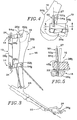
- aligner structure 21 also forms part of jig 10 and is usable, as will be described, to adjust the jig so that jig plane 14 is substantially parallel to a plane that includes the long axis 22 of a metatarsus 24 of a canine (remainder of canine body undepicted). Metatarsus 24 terminates in a paw 24 a which includes toes, or rays, one of which is shown in Fig. 3. The significance of jig 10 to the toes of paw 24 a will be described.
- positioner structure 12 includes locator structure 26 that is usable, as will be described, to locate curvilinear-cut axis 27 (Figs. 4 and 5) after jig 10 is adjusted.
- positioner structure 12 includes first, second and third elongate members 28 a ,28 b ,28 c .
- First and second members 28 a ,28 b are pivotably connected to third member 28 c by placing their respective tab sections 30 a ,30 b into slots 32 a ,32 b formed in opposite ends of third member 28 c .
- the first and second members are held in position relative to the third member by using dogs 34 which are slidably received in holes 36 a , b of third member 28 c and threadably received in threaded holes 38 a , b of third member 28 c .
- compression fastening of the first and second members to the third member with dogs 34 is accomplished by providing a pair of cylindrical bores 40 a , b which are formed in third member 28 c and communicate with corresponding slots 30 a , b via channels 42 a , b .
- compression fastening can be accomplished by extending slots 32 a ,32 b inwardly approximately as far as bores 40 a , b .
- positioner structure 12 shown in Figs. 1 and 3 may take various forms other than the depicted substantially C-shaped configuration with three members.
- the C-shape is preferred because it accommodates offsetting substantially the jig during the TPLO procedure to allow the veterinarian substantial access to the working area of tibial region 16.
- positioner structure 12 As for variations on the form of positioner structure 12, the pivotable connection between second member 28 b and third member 28 c could be omitted and those two members could be formed as one substantially straight member so that positioner structure 12 would have a substantially triangular shape.
- positioner structure 12 must have at least one pivotable connection. Briefly, and referring to Fig. 3, the reason for this requirement is to allow the jig to be used, after the curvilinear cut is made, to hold neutrally the two tibial bone sections 20 a , b relative to one another while proximal section 20 a is correctively rotated with respect to distal section 20 b .
- Figs. 1 and 3 show that it preferably takes the form of two rods 43 a , 43 b .
- the rods are extendable in corresponding openings 44 a - c .
- rod 43 a is structured and positionable in aligner structure 21 to extend toward the distal region of metatarsus 24 while rod 43 b is structured and positionable to extend toward the proximal region of the tarsus, i.e. the bones between metatarsus 24 and tibia 20.
- Fig. 3 is structured and positionable in aligner structure 21 to extend toward the distal region of metatarsus 24
- rod 43 b is structured and positionable to extend toward the proximal region of the tarsus, i.e. the bones between metatarsus 24 and tibia 20.
- rod 43 a is preferably structured with an extent that allows it to be positioned over hock joint (specifically the medial malleolus) 46 and rod 43 b preferably has an extent which allows it to be directed toward the metatarsus, and preferably toward the area between the second and third rays of paw 24 a .
- aligner structure 21 is preferably structured with plural tapered openings 44 a - c for selective use with rods 42 a , b to accommodate a range of canine (or other animal) leg sizes.
- Figs. 2 and 3 show a relatively wide angle (approximately 30° - angle A (15°) + angle B (15°)) being defined by inserting the rods in openings 44 a and 44 c to accommodate a canine with a relatively large leg 18 and metatarsus 24.
- an alternative and smaller angle A (15°) could be defined by the rods for a smaller canine by placing rod 43 b through opening 44 b with rod 43 a being placed through opening 44 a .
- openings 44 a - c each have corresponding top and bottom portions, with the openings being tapered upwardly so that the diameters of the top portions are smaller than the diameters of rods 43 a , b , thereby preventing the rods from extending through the top portions as shown by rod 43 a in Fig. 2 and rods 43 a , b in Fig. 3.
- Fig. 2 also shows that first member 28 a is formed with a threaded bore 45 for receiving a set screw (undepicted) which is usable to fix the vertical position relative to the tibia of to-be-described means for linking the jig to corresponding tibial bone sections.
- a set screw (undepicted) which is usable to fix the vertical position relative to the tibia of to-be-described means for linking the jig to corresponding tibial bone sections.
- first and second members 28 a , b are formed with locator structure 26 which includes corresponding holes 48 a , b (Fig. 5) with long axes that are substantially normal to jig plane 14.
- Holes 48 a , b are structured to receive marking structure 50 for locating curvilinear-cut axis 27.
- marking structure preferably includes pins 52 a , b which are fittable in recesses drilled into tibial section 16 (one such recess 53 shown in Fig. 5) using conventional drilling apparatus (undepicted).
- the marking structure could take any form that is usable to mark the curvilinear-cut axis after it is located, as will soon be described, using jig 10.
- both holes should be usable to receive pins 52 a , b for locating the curvilinear-cut axis so that jig 10 can also be used on the medial side of a tibial region (undepicted) like region 16 but on the right leg (undepicted) of the canine whose left leg is depicted in Fig. 3.
- the jig would be rotated 180° from its position in Fig. 3 so that first member 28 a is where second member 28 b is and vice versa.
- holes 48 a , b are deep enough so that the surfaces of first and second members 28 a , b that define them will guide a drill bit (undepicted) that is placed through a desired one of them (in Fig. 5 the desired hole is hole 48 b ) for movement along the curvilinear-cut axis to drill recess 53 for inserting pin 52 a .
- the drill bit extends through hole 48 a to form recess 53, the same procedure is followed to form a recess (undepicted) for pin 52 b .
- first and second means 54 a , b for linking the jig to corresponding tibial bone sections are also provided.
- first and second linking means are formed as pins 52 a , b , which, in the preferred embodiment, are also usable as marking structure 50.
- jig 10 of the present invention is usable to locate curvilinear-cut axis 27 by first positioning it adjacent tibial region 16.
- aligner structure 21, which may also be thought of as pointer structure is adjusted so that it lies in a plane that includes long axis 22 of metatarsus 24.
- aligner structure 21 is adjusted so that jig plane 14 is substantially parallel to a plane that is parallel to the sagittal plane (i.e. a plane that includes long axis 22 of metatarsus 24).
- the curvilinear-cut axis is located and can be marked by drilling recess 53 (Fig. 5) in tibial section 20 a and placing pin 52 a in it.
- Pin 52 a which now represents a properly located curvilinear-cut axis, may be used with curvilinear cutting apparatus such as my above-identified biradial saw to make a curvilinear through cut along dashed arcuate line 19 (Fig. 3).
- a recess is also drilled in tibial section 20 b and pin 52 b is placed in it so that jig 10 may be linked to tibial region 16 after the curvilinear through cut is made in it.
- jig 10 may be removed, i.e. unlinked, from the tibial region to allow optimal access to the working area during the curvilinear cutting procedure.
- pin 52 a would remain in place to mark curvilinear-cut axis 27 during cutting about it along arcuate line 19.
- jig 10 may be left in a linked position and its vertical position relative to tibia 20 may be fixed by turning set screws (undepicted) in suitably formed threaded bores of members 28 a , b such as threaded bore 45 shown in Fig. 2.
- the jig is unlinked from the tibia before making the cut, it may be relinked to the bone sections after the cut is made and before tibial bone section 20 a is correctively rotated according to the TPLO procedure.
- the jig is used to hold them neutrally relative to one another and to allow for desired movement of the bone sections.
- Such desired movement of the bone sections includes (1) corrective rotation about the curvilinear-cut axis, (2) translational movement up and down with respect to leg 18, and (3) translational movement forward and backward with respect to leg 18.
- Jig 10 will however prevent other types of undesired relative motion between tibial sections 20 a , b , thereby assisting the veterinarian in performing the corrective rotation step of the TPLO procedure.
Landscapes
- Health & Medical Sciences (AREA)
- Surgery (AREA)
- Life Sciences & Earth Sciences (AREA)
- Heart & Thoracic Surgery (AREA)
- Molecular Biology (AREA)
- Oral & Maxillofacial Surgery (AREA)
- Engineering & Computer Science (AREA)
- Biomedical Technology (AREA)
- Dentistry (AREA)
- Medical Informatics (AREA)
- Nuclear Medicine, Radiotherapy & Molecular Imaging (AREA)
- Animal Behavior & Ethology (AREA)
- General Health & Medical Sciences (AREA)
- Public Health (AREA)
- Veterinary Medicine (AREA)
- Surgical Instruments (AREA)
- Amplifiers (AREA)
- Oscillators With Electromechanical Resonators (AREA)
- Circuit Arrangement For Electric Light Sources In General (AREA)
Claims (15)
- Gabarit pour ostéotomie (10) comprenant une structure de positionnement (12) pourvue de perçages qui la traversent,
caractérisé en ce que :ladite structure de positionnement (12) comporte un premier et second perçage (36a, 36b) parallèles et formés à travers elle-même, chaque perçage déflnissant un axe longitudinal;une première tige (43a) qui s'étend vers l'extérieur depuis la structure de positionnement (12) en position adjacente au premier perçage (36a), et s'étendant vers l'extérieur depuis la structure de positionnement (12) dans un plan de gabarit (14) qui est perpendiculaire à l'axe de longitudinal du premier perçage; etune seconde tige (43b) qui s'étend vers l'extérieur depuis la structure de positionnement (12) dans une relation angulaire fixe prédéterminée par rapport à la première tige (43a) en position adjacente au premier perçage (36a), qui diverge depuis la première tige (43a), et qui s'étend vers l'extérieur depuis la structure de positionnement (12) dans le plan de gabarit (14);un troisième perçage (44a) formé dans, et s'étendant jusqu'à l'intérieur de, la structure de positionnement (12) et situé dans le plan de gabarit (14), la première tige (43a) étant introduite dans le troisième perçage (44a);un quatrième perçage (44b) formé dans, et s'étendant jusqu'à l'intérieur de, la structure de positionnement (12) et situé dans le plan de gabarit (14) sous un angle aigu par rapport au troisième perçage (44a), la seconde tige (43b) étant introduite dans le quatrième perçage (44b);un cinquième perçage (44c) formé dans, et s'étendant jusqu'à l'intérieur de, la structure de positionnement (12) et situé dans le plan de gabarit (14) sous un angle approximatif de 30 ou 15° par rapport au troisième et au quatrième perçage (44a - 44b), respectivement;dans lequel la première et la seconde tige (43a - 43b) définissent un angle aigu d'approximativement 15°, et définissent ainsi le plan de gaharit (14) perpendiculaire à l'axe longitudinal du premier perçage (36a). - Gabarit (10) selon la revendication 1, dans lequel :le gabarit (10) est construit pour être utilisé sur un animal présentant une articulation de jarret (46), un tibia (16), un tarse, et un métatarse (24);la première tige (43a) étant susceptible d'être déployée en direction d'une région digitale du métatarse (24a);la seconde tige (43b) étant susceptible d'être déployée en direction d'une région proximale du métatarse (24), en alignant grâce à ceci le plan de gabarit (14) par rapport à un axe longitudinal (22) du métatarse et en plaçant le premier perçage (36a) sensiblement perpendiculairement à un plan sagittal de l'animal ; etle premier perçage (36a) étant réalisé de façon à être placé sur une partie désirée du tibia (16) pour servir de guide pour placer un axe de coupe incurvé (27).
- Gabarit (10) selon la revendication 2, dans lequel la première tige (43a) a une étendue telle qu'elle lui permet d'être positionnée pardessus l'articulation de jarret (46), et la seconde tige (43b) a une étendue telle qu'elle lui permet d'être dirigée vers le métatarse (24).
- Gabarit (10) selon la revendication 2, comprenant en outre un premier bras (52a) pour relier le gabarit (10) à la partie désirée (20a) du tibia (16).
- Gabarit (10) selon la revendication 4, dans lequel le second perçage (36b) est réalisé de façon à être placé sur une partie distale (20b) du tibia (16) par rapport à la partie désirée (20a).
- Gabarit (10) selon la revendication 5, comprenant en outre un second bras (52b) pour relier le gabarit (10) à la partie digitale (20b) du tibia (16) de sorte qu'après avoir procédé à une découpe incurvée (19) dans le tibia (16) avec un appareil de coupe, le gabarit (10) est utilisable pour maintenir de manière neutre les deux parties du tibia (16) l'une par rapport à l'autre tandis que la partie désirée (20a) du tibia (16) est tournée de manière corrective par rapport à la partie distale (20b).
- Gabarit (10) selon la revendication 6, dans lequel le premier et le second bras (52a - 52b) incluent chacun une broche correspondante.
- Gabarit (10) selon la revendication 1, dans lequel :la structure de positionnement (12) comprend un premier élément (28b) et un second élément (28a) qui sont capables de pivoter l'un par rapport à l'autre;le premier élément (28b) comprenant un premier bras (52a) pour relier le gabarit (10) à un tronçon désiré de l'os du tibia (20a);le second élément (28a) comprenant un second bras (52b) pour relier le gaharit (10) à un tronçon distal de l'os du tibia (20b) de telle manière que, après avoir découpé le tronçon désiré depuis le tronçon distal, le gabarit (10) est utilisable pour maintenir de façon neutre les deux tronçons de l'os du tibia l'un par rapport à l'autre, pendant que le tronçon désiré de l'os du tibia est tourné de manière corrective par rapport au tronçon distal de l'os du tibia.
- Gabarit (10) selon la revendication 8, dans lequel le premier et le second bras (52a, 52b) incluent chacun une broche.
- Gabarit (10) selon la revendication 1, dans lequel la structure de positionnement (12) comprend :un premier élément (28c) à travers lequel s'étend le premier perçage (36a) ; etun second élément (28a) fonctionnellement connecté au premier élément (28c), et depuis lequel s'étendent la première et la seconde tige (43a, 43b).
- Gabarit (10) selon la revendication 10, dans lequel la structure de positionnement (12) comprend en outre un troisième élément (28b) fonctionnellement connecté au premier élément.
- Gabarit (10) selon la revendication 1, dans lequel la structure de positionnement (12) comprend :un premier, un second, et un troisième élément (28a - 28c), le premier et le second élément (28a - 28b) étant connectés en pivotement au troisième élément (28c), le premier, le second et le troisième élément étant coplanaires et définissant un plan de positionnement qui est parallèle au plan du gabarit.
- Gabarit (10) selon la revendication 1, comprenant en outre :une première vis de réglage qui communique avec le troisième perçage (44a) pour fixer la première tige (43a) par rapport à la structure de positionnement (12);une seconde vis de réglage qui communique avec le second perçage (44b) pour fixer la seconde tige (43b) par rapport à la structure de positionnement (12).
- Gabarit (10) selon la revendication 1, dans lequel le troisième et le quatrième perçage (44a, 44b) vont en se rétrécissant, de telle façon que la première et la seconde tige (43a, 43) sont tenues par un assemblage serré dans le troisième et le quatrième perçage (44a, 44b), respectivement.
- Gabarit (10) selon la revendication 14, dans lequel une extrémité de chacune de la première et de la seconde tige (43a, 43b) va en se rétrécissant afin de se conformer approximativement au troisième et au quatrième perçage (44a, 44b), respectivement.
Applications Claiming Priority (2)
| Application Number | Priority Date | Filing Date | Title |
|---|---|---|---|
| US90072692A | 1992-06-18 | 1992-06-18 | |
| US900726 | 1992-06-18 |
Publications (2)
| Publication Number | Publication Date |
|---|---|
| EP0574656A1 EP0574656A1 (fr) | 1993-12-22 |
| EP0574656B1 true EP0574656B1 (fr) | 1999-01-20 |
Family
ID=25412994
Family Applications (1)
| Application Number | Title | Priority Date | Filing Date |
|---|---|---|---|
| EP93103732A Expired - Lifetime EP0574656B1 (fr) | 1992-06-18 | 1993-03-09 | Gabarit pour l'ostéotomie |
Country Status (4)
| Country | Link |
|---|---|
| US (1) | US5578038A (fr) |
| EP (1) | EP0574656B1 (fr) |
| AT (1) | ATE175856T1 (fr) |
| DE (1) | DE69323116T2 (fr) |
Cited By (1)
| Publication number | Priority date | Publication date | Assignee | Title |
|---|---|---|---|---|
| KR20110113175A (ko) * | 2009-01-23 | 2011-10-14 | 신세스 게엠바하 | 골절술용 지그 및 톱 가이드 |
Families Citing this family (66)
| Publication number | Priority date | Publication date | Assignee | Title |
|---|---|---|---|---|
| US6162253A (en) * | 1997-12-31 | 2000-12-19 | Iowa State University Research Foundation, Inc. | Total elbow arthroplasty system |
| US5938664A (en) * | 1998-03-31 | 1999-08-17 | Zimmer, Inc. | Orthopaedic bone plate |
| US6306171B1 (en) | 1998-12-09 | 2001-10-23 | Iowa State University Research Foundation, Inc. | Total elbow arthroplasty system |
| GB0107708D0 (en) * | 2001-03-28 | 2001-05-16 | Imp College Innovations Ltd | Bone fixated,articulated joint load control device |
| NL1021815C2 (nl) * | 2002-11-01 | 2004-05-06 | Amc Amsterdam | Zaagmal en een daarbij te gebruiken pasmal voor bewerking van een kuitbeen of dergelijke ten behoeve van een onderkaakreconstructie. |
| DE10258322B3 (de) * | 2002-12-13 | 2004-04-01 | Aesculap Ag & Co. Kg | Führungseinrichtung für ein chirurgisches Bearbeitungswerkzeug |
| US7182766B1 (en) | 2003-08-08 | 2007-02-27 | Stuart Mogul | Adjustable osteotomy guide |
| US20050273112A1 (en) * | 2004-05-26 | 2005-12-08 | Mcnamara Michael G | Three-dimensional osteotomy device and method for treating bone deformities |
| US7727234B2 (en) * | 2004-07-15 | 2010-06-01 | Thorsgard Eric O | Apparatus and method for anterior cruciate repair |
| US20060173458A1 (en) | 2004-10-07 | 2006-08-03 | Micah Forstein | Bone fracture fixation system |
| US20060149275A1 (en) * | 2004-12-14 | 2006-07-06 | Cadmus Calvin M | Apparatus and methods for tibial plateau leveling osteotomy |
| ES2237347B1 (es) * | 2005-03-03 | 2007-08-01 | Universitat Autonoma De Barcelona | Dispositivo para guiar una herramienta de osteotomia u ostectomia. |
| US8034113B2 (en) | 2005-09-27 | 2011-10-11 | Randall Lane Acker | Joint prosthesis and method of implanting same |
| US8012214B2 (en) | 2005-09-27 | 2011-09-06 | Randall Lane Acker | Joint prosthesis |
| US8523921B2 (en) | 2006-02-24 | 2013-09-03 | DePuy Synthes Products, LLC | Tibial plateau leveling osteotomy plate |
| US20110208200A1 (en) * | 2006-08-15 | 2011-08-25 | Gary Keffer | Veterinary precision fixation device and method of using the same |
| US20080044244A1 (en) * | 2006-08-15 | 2008-02-21 | Keffer Gary L | Veterinary precision fixation device and method of using the same |
| US9907645B2 (en) * | 2007-05-01 | 2018-03-06 | Moximed, Inc. | Adjustable absorber designs for implantable device |
| US8123805B2 (en) | 2007-05-01 | 2012-02-28 | Moximed, Inc. | Adjustable absorber designs for implantable device |
| US9655648B2 (en) | 2007-05-01 | 2017-05-23 | Moximed, Inc. | Femoral and tibial base components |
| US7611540B2 (en) * | 2007-05-01 | 2009-11-03 | Moximed, Inc. | Extra-articular implantable mechanical energy absorbing systems and implantation method |
| US8100967B2 (en) * | 2007-05-01 | 2012-01-24 | Moximed, Inc. | Adjustable absorber designs for implantable device |
| US8894714B2 (en) | 2007-05-01 | 2014-11-25 | Moximed, Inc. | Unlinked implantable knee unloading device |
| US20100137996A1 (en) * | 2007-05-01 | 2010-06-03 | Moximed, Inc. | Femoral and tibial base components |
| US8709090B2 (en) | 2007-05-01 | 2014-04-29 | Moximed, Inc. | Adjustable absorber designs for implantable device |
| US20080275567A1 (en) | 2007-05-01 | 2008-11-06 | Exploramed Nc4, Inc. | Extra-Articular Implantable Mechanical Energy Absorbing Systems |
| US20110245928A1 (en) | 2010-04-06 | 2011-10-06 | Moximed, Inc. | Femoral and Tibial Bases |
| US20090163959A1 (en) * | 2007-11-05 | 2009-06-25 | Deeter Nick A | Rotational osteotomy plating system |
| US10349980B2 (en) | 2009-08-27 | 2019-07-16 | The Foundry, Llc | Method and apparatus for altering biomechanics of the shoulder |
| ES2477581T3 (es) | 2009-08-27 | 2014-07-17 | Cotera, Inc. | Aparato para la redistribución de fuerzas en uniones articulares |
| US9861408B2 (en) | 2009-08-27 | 2018-01-09 | The Foundry, Llc | Method and apparatus for treating canine cruciate ligament disease |
| US9278004B2 (en) | 2009-08-27 | 2016-03-08 | Cotera, Inc. | Method and apparatus for altering biomechanics of the articular joints |
| US9668868B2 (en) | 2009-08-27 | 2017-06-06 | Cotera, Inc. | Apparatus and methods for treatment of patellofemoral conditions |
| US8679178B2 (en) | 2009-10-20 | 2014-03-25 | Moximed, Inc. | Extra-articular implantable mechanical energy absorbing assemblies having two deflecting members and compliance member |
| US8523948B2 (en) | 2009-10-20 | 2013-09-03 | Moximed, Inc. | Extra-articular implantable mechanical energy absorbing assemblies having a tension member, and methods |
| US9044270B2 (en) | 2011-03-29 | 2015-06-02 | Moximed, Inc. | Apparatus for controlling a load on a hip joint |
| US9468466B1 (en) | 2012-08-24 | 2016-10-18 | Cotera, Inc. | Method and apparatus for altering biomechanics of the spine |
| US20160015426A1 (en) | 2014-07-15 | 2016-01-21 | Treace Medical Concepts, Inc. | Bone positioning and cutting system and method |
| US9687250B2 (en) | 2015-01-07 | 2017-06-27 | Treace Medical Concepts, Inc. | Bone cutting guide systems and methods |
| US10898211B2 (en) | 2015-01-14 | 2021-01-26 | Crossroads Extremity Systems, Llc | Opening and closing wedge osteotomy guide and method |
| US10292713B2 (en) | 2015-01-28 | 2019-05-21 | First Ray, LLC | Freeform tri-planar osteotomy guide and method |
| US10849631B2 (en) | 2015-02-18 | 2020-12-01 | Treace Medical Concepts, Inc. | Pivotable bone cutting guide useful for bone realignment and compression techniques |
| US10376268B2 (en) | 2015-02-19 | 2019-08-13 | First Ray, LLC | Indexed tri-planar osteotomy guide and method |
| AU2016294588B2 (en) | 2015-07-14 | 2021-06-17 | Treace Medical Concepts, Inc. | Bone positioning guide |
| US10849663B2 (en) | 2015-07-14 | 2020-12-01 | Treace Medical Concepts, Inc. | Bone cutting guide systems and methods |
| US9622805B2 (en) | 2015-08-14 | 2017-04-18 | Treace Medical Concepts, Inc. | Bone positioning and preparing guide systems and methods |
| US10342590B2 (en) | 2015-08-14 | 2019-07-09 | Treace Medical Concepts, Inc. | Tarsal-metatarsal joint procedure utilizing fulcrum |
| US11278337B2 (en) | 2015-08-14 | 2022-03-22 | Treace Medical Concepts, Inc. | Tarsal-metatarsal joint procedure utilizing fulcrum |
| AU2016323600B2 (en) | 2015-09-18 | 2021-06-24 | Treace Medical Concepts, Inc. | Joint spacer systems and methods |
| US11076863B1 (en) | 2016-08-26 | 2021-08-03 | Treace Medical Concepts, Inc. | Osteotomy procedure for correcting bone misalignment |
| US10582936B1 (en) | 2016-11-11 | 2020-03-10 | Treace Medical Concepts, Inc. | Devices and techniques for performing an osteotomy procedure on a first metatarsal to correct a bone misalignment |
| CN107550552B (zh) * | 2017-09-29 | 2024-05-24 | 宁波市第六医院 | 一种跟骨固定支架 |
| EP3820387A4 (fr) | 2018-07-11 | 2022-07-06 | Treace Medical Concepts, Inc. | Compresseur-distracteur pour réalignement angulaire de parties osseuses |
| US11583323B2 (en) | 2018-07-12 | 2023-02-21 | Treace Medical Concepts, Inc. | Multi-diameter bone pin for installing and aligning bone fixation plate while minimizing bone damage |
| US11607250B2 (en) | 2019-02-13 | 2023-03-21 | Treace Medical Concepts, Inc. | Tarsal-metatarsal joint procedure utilizing compressor-distractor and instrument providing sliding surface |
| KR20220042412A (ko) * | 2019-07-26 | 2022-04-05 | 크로스로즈 익스트레미티 시스템즈 엘엘씨 | 빼 재배치 가이드 시스템 및 절차 |
| CA3146564A1 (fr) | 2019-08-07 | 2021-02-11 | Jason May | Instrument bi-planaire pour intervention de coupe osseuse et de realignement d'articulation |
| US11889998B1 (en) | 2019-09-12 | 2024-02-06 | Treace Medical Concepts, Inc. | Surgical pin positioning lock |
| WO2021051098A1 (fr) | 2019-09-13 | 2021-03-18 | Inmotus Medical Llc | Procédés et instrumentation chirurgicaux robotisés |
| US11890039B1 (en) | 2019-09-13 | 2024-02-06 | Treace Medical Concepts, Inc. | Multi-diameter K-wire for orthopedic applications |
| US11986251B2 (en) | 2019-09-13 | 2024-05-21 | Treace Medical Concepts, Inc. | Patient-specific osteotomy instrumentation |
| AU2021212261A1 (en) | 2020-01-31 | 2022-08-18 | Treace Medical Concepts, Inc. | Metatarsophalangeal joint preparation and metatarsal realignment for fusion |
| JP2023514605A (ja) | 2020-02-19 | 2023-04-06 | クロスローズ エクストリミティ システムズ リミテッド ライアビリティ カンパニー | ラピダスバニオン修復法のためのシステム及び方法 |
| JP2023526473A (ja) | 2020-05-19 | 2023-06-21 | トリース メディカル コンセプツ,インコーポレイティド | 中足骨内転を治療するための装置及び技術 |
| US11963847B2 (en) | 2021-11-03 | 2024-04-23 | DePuy Synthes Products, Inc. | TPLO plate compression system and method |
| USD1011524S1 (en) | 2022-02-23 | 2024-01-16 | Treace Medical Concepts, Inc. | Compressor-distractor for the foot |
Family Cites Families (30)
| Publication number | Priority date | Publication date | Assignee | Title |
|---|---|---|---|---|
| US2251209A (en) * | 1940-02-17 | 1941-07-29 | Stader Otto | Bone splint |
| US2346346A (en) * | 1941-01-21 | 1944-04-11 | Anderson Roger | Fracture immobilization splint |
| US2393831A (en) * | 1942-12-29 | 1946-01-29 | Stader Otto | Bone splint |
| US2406987A (en) * | 1943-01-04 | 1946-09-03 | Anderson Roger | Fracture splint |
| US2333033A (en) * | 1943-06-11 | 1943-10-26 | Leslie E Mraz | Bone splint |
| US2391537A (en) * | 1943-09-27 | 1945-12-25 | Anderson Roger | Ambulatory rotating reduction and fixation splint |
| US2393694A (en) * | 1945-04-10 | 1946-01-29 | Otto S Kirschner | Surgical apparatus |
| GB1582133A (en) * | 1976-04-30 | 1980-12-31 | Nat Res Dev | Orthopaedic fracture fixing apparatus |
| IT1107380B (it) * | 1978-11-24 | 1985-11-25 | Barbiero Aldino | Fissatore esterno monolaterale a barre sovrapposte per la riduzione di fratture ossee |
| US4952214A (en) * | 1981-08-20 | 1990-08-28 | Ohio Medical Instrument Co., Inc. | Arcuate osteotomy blade, blade guide, and cutting method |
| US5147364A (en) * | 1981-08-20 | 1992-09-15 | Ohio Medical Instrument Company | Osteotomy saw/file, cutting guide and method |
| NO149831C (no) * | 1981-11-27 | 1984-07-04 | Per Helland | Innretning for ekstern korrigering og fikseirng av knokkeldelene i et bruddsted |
| US4696293A (en) * | 1982-09-30 | 1987-09-29 | Ciullo Jerome V | Hinged external fixator |
| US4509511A (en) * | 1983-06-30 | 1985-04-09 | Neufeld John A | Method and apparatus for corrective osteotomy |
| US4565191A (en) * | 1984-01-12 | 1986-01-21 | Slocum D Barclay | Apparatus and method for performing cuneiform osteotomy |
| CH663347A5 (de) * | 1984-01-19 | 1987-12-15 | Synthes Ag | Fixateur zum fixieren von knochenstuecken. |
| US4750481A (en) * | 1984-04-16 | 1988-06-14 | Reese H William | Osteotomy appliances and method |
| US4730608A (en) * | 1986-03-05 | 1988-03-15 | Schlein Allen P | External bone-anchoring fixator |
| DE3614305A1 (de) * | 1986-04-29 | 1987-11-12 | Baehr Geb Green Judith M | Aeusserlich anwendbarer fixateur |
| SU1473762A1 (ru) * | 1987-01-12 | 1989-04-23 | Калининский Государственный Медицинский Институт | Компрессионно-дистракционный аппарат |
| US4938762A (en) * | 1987-12-16 | 1990-07-03 | Protek Ag | Reference system for implantation of condylar total knee prostheses |
| US4848368A (en) * | 1988-04-25 | 1989-07-18 | Kronner Richard F | Universal external fixation frame assembly |
| BR8807741A (pt) * | 1988-07-26 | 1990-10-16 | V Kurgansky Nauchny Ts Vosstan | Aparelho de tracao para osteosintese de ossos tubulares curtos |
| DE3842255C2 (de) * | 1988-12-15 | 1995-08-03 | Leibinger Medizintech | Externe Knochenbruchteil-Verbindungsvorrichtung |
| IT1234756B (it) * | 1989-03-17 | 1992-05-26 | Orthofix Srl | Fissatore esterno particolarmente adatto per essere applicato sui bacini. |
| FR2645428A1 (fr) * | 1989-04-11 | 1990-10-12 | Hardy Jean Marie | Fixateur pour intervention orthopedique |
| US4922896A (en) * | 1989-05-05 | 1990-05-08 | John M. Agee | Colles' fracture splint |
| CH680769A5 (fr) * | 1989-08-23 | 1992-11-13 | Jaquet Orthopedie | |
| US5078719A (en) * | 1990-01-08 | 1992-01-07 | Schreiber Saul N | Osteotomy device and method therefor |
| US5171244A (en) * | 1990-01-08 | 1992-12-15 | Caspari Richard B | Methods and apparatus for arthroscopic prosthetic knee replacement |
-
1993
- 1993-03-09 AT AT93103732T patent/ATE175856T1/de not_active IP Right Cessation
- 1993-03-09 EP EP93103732A patent/EP0574656B1/fr not_active Expired - Lifetime
- 1993-03-09 DE DE69323116T patent/DE69323116T2/de not_active Expired - Fee Related
-
1994
- 1994-06-06 US US08/254,478 patent/US5578038A/en not_active Expired - Fee Related
Cited By (1)
| Publication number | Priority date | Publication date | Assignee | Title |
|---|---|---|---|---|
| KR20110113175A (ko) * | 2009-01-23 | 2011-10-14 | 신세스 게엠바하 | 골절술용 지그 및 톱 가이드 |
Also Published As
| Publication number | Publication date |
|---|---|
| DE69323116T2 (de) | 1999-06-24 |
| US5578038A (en) | 1996-11-26 |
| DE69323116D1 (de) | 1999-03-04 |
| EP0574656A1 (fr) | 1993-12-22 |
| ATE175856T1 (de) | 1999-02-15 |
Similar Documents
| Publication | Publication Date | Title |
|---|---|---|
| EP0574656B1 (fr) | Gabarit pour l'ostéotomie | |
| US8529571B2 (en) | Jig and saw guides for use in osteotomies | |
| US5601565A (en) | Osteotomy method and apparatus | |
| EP3528716B1 (fr) | Systèmes d'ostéotomie | |
| US5374271A (en) | Double nail guiding system for targeting of distal screw holes of interlocking nails | |
| US20210161575A1 (en) | Bone fixation system, assembly, implants, devices, alignment guides, and methods of use | |
| US7540874B2 (en) | Method and device for use in osteotomy | |
| US5643272A (en) | Method and apparatus for tibial resection | |
| US5968050A (en) | Positioning a tibial tunnel | |
| US6027504A (en) | Device and method for producing osteotomies | |
| EP2155119B1 (fr) | Clou centromédullaire flexible | |
| US5935128A (en) | Orthopaedic template system including a joint locator | |
| US6796986B2 (en) | Adjustable tibial osteotomy jig and method | |
| US6190390B1 (en) | Apparatus and method for creating a dome tibial osteotomy | |
| US4644943A (en) | Bone fixation device | |
| US20160310191A1 (en) | Articulating Syndesmosis Targeting Guide Device and Method | |
| US20060229621A1 (en) | Apparatus and methods for tibial plateau leveling osteotomy | |
| JPS63153057A (ja) | 外科手術装置 | |
| PT809471E (pt) | Guia de corte femoral distal | |
| US20240215994A1 (en) | Implant, alignment guides, system and methods of use | |
| US11589877B2 (en) | Wedge osteotomy device and method of use | |
| JP3815240B2 (ja) | 高位脛骨骨切り術に使用する治具 | |
| JPS62101240A (ja) | 骨への鋼線刺入位置決め装置 | |
| AU2023222926A1 (en) | Veterinary surgical jig and corresponding bone plate | |
| WO2024164009A2 (fr) | Guides, instrumentation ainsi que procédés d'utilisation et d'assemblage pour interventions d'ostéotomie |
Legal Events
| Date | Code | Title | Description |
|---|---|---|---|
| PUAI | Public reference made under article 153(3) epc to a published international application that has entered the european phase |
Free format text: ORIGINAL CODE: 0009012 |
|
| AK | Designated contracting states |
Kind code of ref document: A1 Designated state(s): AT BE CH DE DK ES FR GB GR IE IT LI LU MC NL PT SE |
|
| 17P | Request for examination filed |
Effective date: 19940622 |
|
| 17Q | First examination report despatched |
Effective date: 19970123 |
|
| GRAG | Despatch of communication of intention to grant |
Free format text: ORIGINAL CODE: EPIDOS AGRA |
|
| GRAG | Despatch of communication of intention to grant |
Free format text: ORIGINAL CODE: EPIDOS AGRA |
|
| GRAH | Despatch of communication of intention to grant a patent |
Free format text: ORIGINAL CODE: EPIDOS IGRA |
|
| GRAH | Despatch of communication of intention to grant a patent |
Free format text: ORIGINAL CODE: EPIDOS IGRA |
|
| GRAA | (expected) grant |
Free format text: ORIGINAL CODE: 0009210 |
|
| AK | Designated contracting states |
Kind code of ref document: B1 Designated state(s): AT BE CH DE DK ES FR GB GR IE IT LI LU MC NL PT SE |
|
| PG25 | Lapsed in a contracting state [announced via postgrant information from national office to epo] |
Ref country code: SE Free format text: THE PATENT HAS BEEN ANNULLED BY A DECISION OF A NATIONAL AUTHORITY Effective date: 19990120 Ref country code: NL Free format text: LAPSE BECAUSE OF FAILURE TO SUBMIT A TRANSLATION OF THE DESCRIPTION OR TO PAY THE FEE WITHIN THE PRESCRIBED TIME-LIMIT Effective date: 19990120 Ref country code: LI Free format text: LAPSE BECAUSE OF FAILURE TO SUBMIT A TRANSLATION OF THE DESCRIPTION OR TO PAY THE FEE WITHIN THE PRESCRIBED TIME-LIMIT Effective date: 19990120 Ref country code: GR Free format text: LAPSE BECAUSE OF NON-PAYMENT OF DUE FEES Effective date: 19990120 Ref country code: ES Free format text: THE PATENT HAS BEEN ANNULLED BY A DECISION OF A NATIONAL AUTHORITY Effective date: 19990120 Ref country code: CH Free format text: LAPSE BECAUSE OF FAILURE TO SUBMIT A TRANSLATION OF THE DESCRIPTION OR TO PAY THE FEE WITHIN THE PRESCRIBED TIME-LIMIT Effective date: 19990120 Ref country code: BE Free format text: LAPSE BECAUSE OF FAILURE TO SUBMIT A TRANSLATION OF THE DESCRIPTION OR TO PAY THE FEE WITHIN THE PRESCRIBED TIME-LIMIT Effective date: 19990120 Ref country code: AT Free format text: LAPSE BECAUSE OF FAILURE TO SUBMIT A TRANSLATION OF THE DESCRIPTION OR TO PAY THE FEE WITHIN THE PRESCRIBED TIME-LIMIT Effective date: 19990120 |
|
| REF | Corresponds to: |
Ref document number: 175856 Country of ref document: AT Date of ref document: 19990215 Kind code of ref document: T |
|
| ITF | It: translation for a ep patent filed | ||
| REG | Reference to a national code |
Ref country code: CH Ref legal event code: EP |
|
| REG | Reference to a national code |
Ref country code: IE Ref legal event code: FG4D |
|
| REF | Corresponds to: |
Ref document number: 69323116 Country of ref document: DE Date of ref document: 19990304 |
|
| PG25 | Lapsed in a contracting state [announced via postgrant information from national office to epo] |
Ref country code: LU Free format text: LAPSE BECAUSE OF NON-PAYMENT OF DUE FEES Effective date: 19990309 |
|
| PG25 | Lapsed in a contracting state [announced via postgrant information from national office to epo] |
Ref country code: IE Free format text: LAPSE BECAUSE OF NON-PAYMENT OF DUE FEES Effective date: 19990320 |
|
| PG25 | Lapsed in a contracting state [announced via postgrant information from national office to epo] |
Ref country code: PT Free format text: LAPSE BECAUSE OF FAILURE TO SUBMIT A TRANSLATION OF THE DESCRIPTION OR TO PAY THE FEE WITHIN THE PRESCRIBED TIME-LIMIT Effective date: 19990420 Ref country code: DK Free format text: LAPSE BECAUSE OF FAILURE TO SUBMIT A TRANSLATION OF THE DESCRIPTION OR TO PAY THE FEE WITHIN THE PRESCRIBED TIME-LIMIT Effective date: 19990420 |
|
| PG25 | Lapsed in a contracting state [announced via postgrant information from national office to epo] |
Ref country code: DE Free format text: LAPSE BECAUSE OF FAILURE TO SUBMIT A TRANSLATION OF THE DESCRIPTION OR TO PAY THE FEE WITHIN THE PRESCRIBED TIME-LIMIT Effective date: 19990421 |
|
| ET | Fr: translation filed | ||
| NLV1 | Nl: lapsed or annulled due to failure to fulfill the requirements of art. 29p and 29m of the patents act | ||
| REG | Reference to a national code |
Ref country code: CH Ref legal event code: PL |
|
| PG25 | Lapsed in a contracting state [announced via postgrant information from national office to epo] |
Ref country code: MC Free format text: LAPSE BECAUSE OF NON-PAYMENT OF DUE FEES Effective date: 19990930 |
|
| PLBE | No opposition filed within time limit |
Free format text: ORIGINAL CODE: 0009261 |
|
| STAA | Information on the status of an ep patent application or granted ep patent |
Free format text: STATUS: NO OPPOSITION FILED WITHIN TIME LIMIT |
|
| 26N | No opposition filed | ||
| REG | Reference to a national code |
Ref country code: IE Ref legal event code: MM4A |
|
| REG | Reference to a national code |
Ref country code: FR Ref legal event code: CA |
|
| REG | Reference to a national code |
Ref country code: GB Ref legal event code: IF02 |
|
| PGFP | Annual fee paid to national office [announced via postgrant information from national office to epo] |
Ref country code: GB Payment date: 20050318 Year of fee payment: 13 |
|
| PGFP | Annual fee paid to national office [announced via postgrant information from national office to epo] |
Ref country code: DE Payment date: 20050530 Year of fee payment: 13 |
|
| PG25 | Lapsed in a contracting state [announced via postgrant information from national office to epo] |
Ref country code: GB Free format text: LAPSE BECAUSE OF NON-PAYMENT OF DUE FEES Effective date: 20060309 |
|
| GBPC | Gb: european patent ceased through non-payment of renewal fee |
Effective date: 20060309 |
|
| REG | Reference to a national code |
Ref country code: FR Ref legal event code: ST Effective date: 20061130 |
|
| PGFP | Annual fee paid to national office [announced via postgrant information from national office to epo] |
Ref country code: IT Payment date: 20070627 Year of fee payment: 15 |
|
| PG25 | Lapsed in a contracting state [announced via postgrant information from national office to epo] |
Ref country code: FR Free format text: LAPSE BECAUSE OF NON-PAYMENT OF DUE FEES Effective date: 20060331 |
|
| PGFP | Annual fee paid to national office [announced via postgrant information from national office to epo] |
Ref country code: FR Payment date: 20070308 Year of fee payment: 15 |
|
| PG25 | Lapsed in a contracting state [announced via postgrant information from national office to epo] |
Ref country code: IT Free format text: LAPSE BECAUSE OF NON-PAYMENT OF DUE FEES Effective date: 20080309 |