EP0572492B1 - Verfahren und Vorrichtung zur Dämpfung akustischer Schwingungen in einem Medium - Google Patents
Verfahren und Vorrichtung zur Dämpfung akustischer Schwingungen in einem Medium Download PDFInfo
- Publication number
- EP0572492B1 EP0572492B1 EP92905463A EP92905463A EP0572492B1 EP 0572492 B1 EP0572492 B1 EP 0572492B1 EP 92905463 A EP92905463 A EP 92905463A EP 92905463 A EP92905463 A EP 92905463A EP 0572492 B1 EP0572492 B1 EP 0572492B1
- Authority
- EP
- European Patent Office
- Prior art keywords
- resonator
- signal
- medium
- frequency
- selected frequency
- Prior art date
- Legal status (The legal status is an assumption and is not a legal conclusion. Google has not performed a legal analysis and makes no representation as to the accuracy of the status listed.)
- Expired - Lifetime
Links
Images

Classifications
-
- G—PHYSICS
- G10—MUSICAL INSTRUMENTS; ACOUSTICS
- G10K—SOUND-PRODUCING DEVICES; METHODS OR DEVICES FOR PROTECTING AGAINST, OR FOR DAMPING, NOISE OR OTHER ACOUSTIC WAVES IN GENERAL; ACOUSTICS NOT OTHERWISE PROVIDED FOR
- G10K11/00—Methods or devices for transmitting, conducting or directing sound in general; Methods or devices for protecting against, or for damping, noise or other acoustic waves in general
- G10K11/16—Methods or devices for protecting against, or for damping, noise or other acoustic waves in general
- G10K11/172—Methods or devices for protecting against, or for damping, noise or other acoustic waves in general using resonance effects
Definitions
- This invention relates to a method and apparatus for attenuating acoustic vibrations in a medium, and more particularly to a method and apparatus to control a tunable acoustic resonator to effect such attenuation.
- an acoustic resonator can be used to attenuate acoustic vibration in a system (DE 3729765).
- the resonant frequency of the resonator and hence the frequency of the acoustic vibrations that are attenuated in a system is dependent on the dimensions and structure or type of resonator employed.
- resonators of fixed structure are employed as disclosed in DE 3729765. This arrangement is however limited in that if the frequency of the acoustic vibration to be attenuated changes, then the efficiency of the resonator as an attenuator decreases as the frequency moves away from the resonant frequency.
- a resonator is disclosed in EP 0039459 which attempts to overcome this limitation in relation to the use of a resonator to attenuate the noise generated by a turbo machine.
- Two specific types of resonators are disclosed, one being a quarter wave resonator and the other being a Helmholtz resonator.
- the resonant frequency of the quarter wave resonator is varied by varying the length of pipe, whilst the resonant frequency of the Helmholtz resonator is varied by varying the volume of the resonant chamber.
- the resonant frequency is variable to enable attenuation of unwanted variable frequency acoustic vibrations created by the turbo machine. This document does not however address the problem of how such resonators can be accurately controlled.
- the present invention provides apparatus for attenuating acoustic vibrations in a medium, said apparatus comprising a tunable acoustic resonator with an open end for interfacing with said medium outside of said resonator, at least one transducer to provide a first signal indicative of a dynamic parameter of the medium within said resonator, and a resonator controller operable in response to said first signal to tune said resonator to a selected frequency of said acoustic vibrations.
- the present invention also provides a method of attenuating acoustic vibrations in a medium comprising the steps of interfacing a tunable acoustic resonator with said medium outside of said resonator, measuring a dynamic parameter of the medium within said resonator to give a first signal, and tuning said resonator to a selected frequency of said acoustic vibrations in response to said first signal.
- the present invention is applicable to any acoustic resonators such as a quarter wave resonator, a Helmholtz resonator or a mechanical resonator.
- the first signal can provide a measure of the dynamic pressure at a point within the resonant chamber.
- the first signal can provide a measure of the motion of the oscillating mass. If an air chamber is used as the spring for a mechanical resonator then the first signal can provide a measure of the dynamic pressure within the chamber.
- the resonator controller is operative to determine said selected frequency in response to a predetermined characteristic of said first signal and to tune said resonator so as to maximise the amplitude of said first signal at said selected frequency.
- the present invention can provide for the adaptive control of a resonator without the need for any external signal indicating the frequency of the acoustic vibrations to be attenuated.
- an algorithm would be performed using digital processing apparatus which had stored the characteristics of the resonator and which could therefore calculate the frequency of the acoustic vibrations reaching the resonator and attenuate the frequency with the largest amplitude for example.
- the processing apparatus in this instance has knowledge of the dimensions of the resonator for example. This could be obtained from knowledge of for example the position of a piston moveable to vary the resonant volume in a Helmholtz or quarter wave resonator.
- the processor may alternatively be an analogue processor.
- a reference means provides a reference signal indicative of said selected frequency and the resonator controller is operative to tune said resonator so as to maximise the amplitude of said first signal at said selected frequency.
- An arrangement that can accomplish this comprises a filter means to band-pass filter the first signal at the reference signal frequency, wherein said resonator controller is operative to tune said resonator so as to maximise the amplitude of the band-pass filtered first signal.
- the apparatus includes a second signal indicative of a dynamic parameter of said medium outside of said resonator and reference means providing a reference signal indicative of said selected frequency, wherein said resonator controller is operative to tune said resonator so as to maintain the phase difference between the first and second signals at said selected frequency substantially at 90°.
- the resonator controller preferably includes a band-pass filter for each of said first and second signals, to band-pass filter each resonator signal at said reference signal frequency, a multiplier to receive the filtered first and second signals and output a combined signal and an integrator or low pass filter to receive the combined signal and output a resonator control signal.
- a transducer can be provided in the medium to provide the second signal indicative of the dynamic pressure within the medium outside of said resonator.
- the second transducer provides a measure of the force applied to the resonator whilst the first transducer provides a measure of the response by the resonator to that force.
- the present invention is applicable for use in the reduction of transmission of acoustic vibrations along a duct, and in particular to the reduction of acoustic vibrations along an exhaust or inlet pipe of an internal combustion engine; although the present invention is by no means limited as such and may be used to reduce unwanted acoustic vibrations in any system.
- the reference means may comprise either a peak detection filter to detect the frequency of the acoustic vibrations with the largest amplitude, or it can provide a synchronising signal to the rotation rate of the engine.
- the resonator controller is operative to detect the frequency of the acoustic vibrations with the largest amplitude by utilising its knowledge of the characteristics of the resonator.
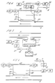
- Figure 1 illustrates three types of resonators that can be employed in cancelling undesired acoustic vibration.
- the resonators are shown connected to a duct 2, although the present invention is not limited as such.
- the resonator could be a Helmholtz resonator 1 where the air mass in the neck oscillates on the natural spring created by the air in the bulb. Damping is produced partly by flow effects in the neck, but mainly by sound radiation into the duct.
- ⁇ o C S lV
- the resonant frequency of the resonator can be adjusted by adjustinq the neck length, neck area or bulb volume.
- the resonator could be a quarter wave length resonator 3, which can be viewed as a special case of a Helmholtz resonator, where the neck and the bulb have the same diameter.
- the effective mass and stiffness are both continuous.
- the resonant frequency of the quarter wave length resonator can be adjusted by varying the length of the side branch. This can be implemented for example by using a sliding piston.
- the resonator can also be a mechanical resonator 4 with a piston of mass M on a spring in a side branch.
- the most simple arrangement is to adjust the spring stiffness. This could be adjusted for example by having a variable rate spring or a compressed gas spring where the spring stiffness is proportional to the gas pressure.
- any one or more of these three parameters can be measured.
- accurate control of the resonator can be implemented since the accurate resonant frequency of the resonator is known.
- the measurement of, for instance, gas pressure within the resonator has the advantage of automatically compensating for any temperature variations that may occur between the medium in which the undesired acoustic vibrations are being transmitted and the medium contained within the resonant cavity.
- control schemes that can be used to ensure that resonance is obtained at the desired frequency can be based on the three common behavioural characteristics of the resonator at resonance in that:
- the third control arrangement has the advantage that by measuring the phase, one has direct knowledge of which direction to make adjustments of the resonance frequency of the resonator, thus making adaption very fast and robust.
- the control system is fully adaptive and can respond to local changes in the environment (sound, speed, temperature, etc.).
- the required parameters of the resonator can be measured using transducers and the output of these transducers can be filtered so as to be sensitive only to the frequency of interest, i.e. the undesired acoustic vibration frequency. This frequency is selected according to the desired function of the resonator.
- any of the resonators hereinbefore described are attached to attenuate acoustic vibrations in a medium (e.g. in a duct), sound travelling in the medium (along the duct) will be reflected at the point of fixture. This is how the resonators operate to minimise transmission of acoustic vibrations through the medium.
- a resonator can be used in the inlet or exhaust of an internal combustion engine to minimise transmitted sound especially at the resonant frequency or frequencies.
- the resonator can be automatically tuned by adjusting its effective mass or spring parameters.
- the frequency of interest can be selected in several ways. It can have a fixed relation to one harmonic of the engine and can be obtained from an engine tachometer signal for example. Alternatively, it can automatically be chosen to be the frequency at which attenuation would be the most effective at any given time. This could be achieved by identifying the loudest frequency component from for example a tailpipe or inlet microphone and the resonator could be adapted to that frequency.
- a resonator controller could have stored in a memory the characteristics of the resonator and could perform an algorithm to ascertain the frequency of the acoustic vibrations impinging on the open end of the resonator having the largest amplitude. The resonator could then be tuned to this frequency.
- resonators need not be confined to use in ducts.
- the resonators may be used to control noise in a volume such as a vehicle cabin and to improve the efficiency of acoustic attenuation an array of such resonators may be used.
- Figure 2 illustrates a quarter wave resonator 3, attached to a duct 2 via an open end 5.
- the length of the side branch and hence the resonant frequency of the resonator is adjustable using a piston 6 attached to a movable far end wall 7 of the resonator.
- the piston 6 is driven by a motor 8 which is controlled by a control signal transmitted on line 9.
- the transducer 11 provides a measure of the dynamic pressure of the gas at the far end wall of the resonator.
- Signals from the transducer 11 are filtered by a band-pass filter 12, the centre frequency of which is controlled by a signal on line 13 which in this example of this invention is provided from a tachometer 14 of an internal combustion engine.
- the band-pass filter filters the dynamic pressure signals from the transducer 11 to provide a measure of the dynamic pressure at the selected frequency of the acoustic vibrations to be attenuated.
- the output signal from the band-pass filter 12 is then input into a maximum signal detector 15 which detects any decrease in the amplitude of the signal at the required frequency. If a decrease is detected then a signal is output via the amplifier 16 on line 9 to the motor to move the piston 6 and the far end wall 7 to adjust the resonant frequency of the resonator.
- FIG. 3 illustrates a second embodiment of the present invention in which a Helmholtz resonator 1 is connected to a duct 2 via a neck portion 20.
- the Helmholtz resonator has a resonant chamber 21 the volume of which can be varied by moving a far end wall 22 by the action of a piston 6 driven by a motor 8.
- a neck insert 25 which is attached to the far end wall 22 and moves therewith in unison.
- the pressure of the gas within the resonant cavity 21 is measured by a transducer 26 whilst the pressure of the gas in the duct 2 is measured by transducer 27.
- the signals from these two transducers 26 and 27 are individually filtered by band-pass filters 31 and 32 the centre frequencies of which are controlled by a signal on line 28.
- the signal on line 28 represents the selected frequency of the acoustic vibrations to be attenuated, and this signal is provided from filter 29 by peak selection filtering of a signal representing the acoustic vibrations at a position in the duct upstream of the resonator as measured by a transducer 30.
- the selected frequency of the filtered acoustic vibrations that are to be attenuated is decided by selecting the acoustic vibrations in the duct having the largest amplitude.
- the signals from the transducers 26 and 27 after having been filtered by band-pass filters 31 and 32 are multiplied together by the multiplier 33.
- the multiplied signal from the multiplier 33 is then applied to an integrator 34 which supplies the resonator control signal on line 35 to the motor 34 to move the piston 23 and far end wall 22 in order to change the resonant cavity volume, and hence the resonant frequency of the resonator.
- the neck length as well as the volume of the Helmholtz resonator is varied. This provides for extra sensitivity, although only one parameter need be varied.
- the two filtered pressure signals provided from transducers 26 and 27 after filtering in the band-pass filters 31 and 32, will generally have a phase difference of ⁇ between them.
- x(t) k/2 (Cos ⁇ - Cos(2w o t+ ⁇ ))
- the integrator output, y(t) will be approximately y(t) ⁇ k/2 Cos ⁇ (t)
- a low pass filter could alternatively be used instead of the integrator 34 to provide y(t).
- FIG. 4 this diagram illustrates the use of a mechanical resonator 4 attached to a duct 2 for a fluid or gas medium.
- the mechanical resonator comprises a mass 40 suspended at the interface between the resonator 4 and the duct 2 by a diaphragm 41.
- the diaphragm 41 forms an airtight seal across the interface sealing gas in a cavity 42.
- the cavity 42 has a preset regulator valve 43 regulating gas provided by a pump 44.
- the cavity 42 also has a motorised valve 45 to control the pressure there within.
- a transducer in the form of a microphone 27 is provided within the duct adjacent to the interface with the resonator to provide a measure of the pressure in the duct and hence the force applied to the resonator.
- a transducer 47 providing signals indicative of the pressure within the cavity 42.
- the signals from the transducers 27 and 47 are band-pass filtered in filters 31 and 32 with the centre frequency of the filters 31 and 32 controlled by a signal on line 13.
- the signal on line 13 provides a signal representative of the selected frequency of the acoustic vibrations to be attenuated.
- such a signal is provided from the tachometer 14 of an internal combustion engine.
- the filtered signals from the transducers 27 and 47 are then multiplied in the multiplier 33 and the combined signal integrated in integrator 34 to provide the resonator control signal on line 35 which is amplified in amplifier 16 to provide the control signal which controls the motorised valve 45 in order to control the pressure of the gas within the cavity 42.
- the pump 44 provides a constant head of pressure which can be controlled by the preset regulator valve 43, and the pressure in the resonator cavity 42 is varied by opening or closing the motorised valve 45.
- ⁇ o 1 2 ⁇ K eff M
- K eff K 1 + K 2
- this diagram illustrates a Helmholtz resonator 1 connected to a duct 2 via a neck 20.
- the volume of the cavity 21 within the resonator is varied by partially filling it with an incompressible fluid 60.
- the control arrangement illustrated in this diagram is the same as that illustrated in Figure 2 for the quarter wave resonator and like reference numerals denote like components.
- the resonator control signal produced by the controller controls a positive displacement pump 61 which pumps fluid either from or to the reservoir 62.
- FIG. 6 this diagram illustrates use of the same control system as described in Figures 2 and 5 to control a mechanical resonator 4.
- the mass 40 is provided with an accelerometer 46 which measures the motion of the mass 40.
- the signal provided from the accelerometer is equivalent to that provided by the transducer 47 in Figure 4.
- the signal from this is then utilised by the control system as described in relation to Figures 2 and 5 to control the motorised valve 45 as described with respect to Figure 4.
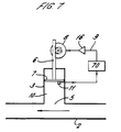
- the resonator controller is different and comprises a digital processing apparatus 70 which has stored characteristics of the resonator to enable it to deconvolve the effects of the resonator on the acoustic vibrations impinging on the open end 5 of the resonator and hence determine the frequency component of the acoustic noise with the largest amplitude.
- a control signal is then output on line 9 to the motor 8 to tune the resonator to the frequency at which the largest amplitude has been detected.
- the characteristics of the resonator need be input to the processor only once and the system needs no reference signals. This system could be used where only small changes in the fluid properties (temperature etc.) are expected.
- a first signal indicative of the vibrations in the resonator 1, 3 or 4 is band-pass filtered with the centre frequency of the band-pass filter 12 being set at the selected frequency of the acoustic vibrations to be attenuated, the centre frequency being controlled by a second signal on the line 13.
- the amplitude of this filtered signal is then detected by a maximum signal detector 15 and a resonator control signal output to maximise the amplitude of the measured first signal at the selected frequency of the acoustic vibrations to be attenuated.
- the first signal can either be a measure of the motion of the mass 40 in a mechanical resonator 4 or it can be a measure of the pressure at a point within the resonant cavity 10 or 21 of either a quarter wave or Helmholtz resonator.
- First signals from the first transducers 26 and 47 and second signals from the second transducers 27 are band-pass filtered at the selected frequency of the acoustic vibration to be attenuated.
- the filtered signals are then multiplied and integrated or filtered to provide a resonator control signal on line 35.
- the resonator control signal will be output whenever the phase difference between the signals from the first and second transducers 26 and 27 or from the first and second transducers 47 and 27 strays from a value of approximately 90°. It is a condition of resonance that to a good approximation the phase difference between these two signals should be 90° and therefore any deviation from this phase difference indicates a drift from resonance.
- This technique has the advantage that the resonator control signal output from the integrator 34 gives an indication of the direction in which to adjust the resonant frequency.
- a resonator and control system as hereinbefore described is used to cancel undesired acoustic noise in a duct, it may be the case that significant force is transmitted to the resonator housing by the action of the resonator.
- a symmetric arrangement of resonators, or a resonator of intrinsic axial symmetry can be used.
- control systems illustrated in Figures 2 to 6 may be implemented either digitally or in an analogue manner.
- the present invention can thus provide a compact unit comprising a resonator and a control system for use in the attenuation of undesired acoustic vibrations in a system such as a duct.
Claims (31)
- Vorrichtung zum Dämpfen von akustischen Vibrationen in einem Medium, welche Vorrichtung einen abstimmbaren akustischen Resonator mit einem offenen Ende zum Ankoppeln an das Medium außerhalb des Resonators, wenigstens einen Wandler zum Liefern eines ersten Signals, das für einen dynamischen Parameter des Mediums innerhalb des Resonators kennzeichnend ist, und eine Resonatorsteuereinheit aufweist, die in Reaktion auf das erste Signal betreibbar ist, um den Resonator auf eine ausgewählte Frequenz der akustischen Vibrationen abzustimmen.
- Vorrichtung nach Anspruch 1, bei der die Resonatorsteuereinheit so arbeitet, daß sie die ausgewählte Frequenz als Reaktion auf eine vorbestimmte Charakteristik des ersten Signals bestimmt, das für den dynamischen Parameter des Mediums kennzeichnend ist, und den Resonator so abstimmt, daß die Amplitude des ersten Signals bei der ausgewählten Frequenz maximiert wird.
- Vorrichtung nach Anspruch 1, die Bezugsmittel einschließen, die ein Bezugssignal liefern, das für die ausgewählte Frequenz kennzeichnend ist, wobei die Resonatorsteuereinheit so arbeitet, daß sie den Resonator so abstimmt, daß die Amplitude des ersten Signals maximiert wird, das für den dynamischen Parameter des Mediums bei der ausgewählten Frequenz kennzeichnend ist.
- Vorrichtung nach Anspruch 3, bei der die Resonatorsteuereinheit Filtermittel für Bandpaßfilterung des ersten Signals aufweist, das kennzeichnend für den dynamischen Parameter des Mediums bei der Bezugssignalfrequenz ist, wobei die Resonatorsteuereinheit so arbeitet, daß sie den Resonator so abstimmt, daß die Amplitude des bandpaßgefilterten ersten Signals maximiert wird.
- Vorrichtung nach Anspruch 1, die einen zweiten Wandler zum Liefern einen zweiten Signals, das kennzeichnend für einen dynamischen Parameter des Mediums außerhalb des Resonators ist, und Bezugsmittel aufweist, die ein Bezugssignal liefern, das kennzeichnend für die ausgewählte Frequenz ist, wobei die Resonatorsteuereinheit so arbeitet, daß sie den Resonator so abstimmt, daß die Phasendifferenz zwischen den ersten und zweiten Signalen bei der ausgewählten Frequenz im wesentlichen bei 90° gehalten wird.
- Vorrichtung nach Anspruch 5, bei der die Resonatorsteuereinheit einen Bandpaßfilter für jedes der ersten und zweiten Signale, um jedes Signal bei der Bezugssignalfrequenz einer Bandpaßfilterung zu unterziehen, einen Multiplier zum Empfangen der gefilterten Signale und zum Ausgeben eines kombinierten Signals und einen Integrator oder Tiefpaßfilter zum Empfangen des kombinierten Signals und zum Ausgeben eines Resonatorsteuersignals aufweist.
- Vorrichtung nach Anspruch 1, bei der der Resonator eine Resonanzkammer und einen ersten Wandler aufweist, der darin angebracht ist, um das erste Signal zu liefern, das ein Maß für den dynamischen Druck des Mediums an einer Stelle innerhalb der Resonanzkammer fern von dem offenen Ende der Kammer ist.
- Vorrichtung nach einem vorangehenden Anspruch, bei der der Resonator ein Helmholtz-Resonator ist.
- Vorrichtung nach Anspruch 7, bei der der Resonator ein Viertelwellenlängen-Resonator ist und der erste Wandler an der fernen Endwand der Resonanzkammer angebracht ist.
- Vorrichtung nach Anspruch 8 oder 9, bei der die Resonatorsteuereinheit Mittel aufweist, eine ferne Endwand der Resonanzkammer zu bewegen.
- Vorrichtunq nach einem der Ansprüche 1 bis 7, bei der der Resonator ein mechanischer Resonator mit einer gefederten Masse ist, wobei die Masse einen daran angebrachten Bewegungswandler aufweist, um das erste Signal zu liefern, das ein Maß für die Bewegung der Masse ist.
- Vorrichtung nach Anspruch 11, bei der der Bewegungswandler ein Beschleunigungsmesser ist, um ein Maß für die Beschleunigung der Masse zu liefern.
- Vorrichtung nach Anspruch 11 oder 12, bei der die Masse von einer Membran nahe dem offenen Ende des Resonators schwebend gehalten wird und die Federwirkung durch ein Gas geliefert wird, das in der Kammer durch die Membran eingeschlossen ist.
- Vorrichtung nach Anspruch 13, bei der der Druck des Gases innerhalb des Hohlraums durch die Resonatorsteuereinheit gesteuert wird.
- Vorrichtung nach einem der Ansprüche 5 bis 14, die einen zweiten Wandler einschließt, der in dem Medium außerhalb des Resonators angebracht ist, um das zweite Signal zu liefern, das für den dynamischen Druck im Medium außerhalb des Resonators kennzeichnend ist.
- Vorrichtung nach einem vorangehenden Anspruch, die dazu ausgebildet ist, die Übertragung von unerwünschter akustischer Vibration entlang einer Leitung oder eines Kanals zu verringern.
- Vorrichtung nach einem voranqehenden Anspruch, die dazu ausgebildet ist, die Übertragung von akustischer Vibration in einem Auspuffrohr von einem Verbrennungsmotor zu verringern.
- Vorrichtung nach einem der Ansprüche 3 bis 17, wobei die Bezugsmittel einen Spitzendetektionsfilter aufweisen, um die Frequenz der akustischen Vibrationen mit der größten Amplitude zu detektieren und um das Bezugssignal bei der Frequenz auszugeben.
- Vorrichtung nach Anspruch 17, wobei die Bezugsmittel so arbeiten, daß sie das Bezugssignal mit der Umdrehungsgeschwindigkeit des Motors synchronisieren.
- Verfahren zum Abschwächen von akustischen Vibrationen in einem Medium, das die Schritte aufweist, einen abstimmbaren akustischen Resonator an das Medium außerhalb des Resonators anzukoppeln, einen dynamischen Parameter des Mediums innerhalb des Resonators zu messen, um ein erstes Signal zu erhalten, und den Resonator auf eine ausgewählte Frequenz der akustischen Vibrationen als Reaktion auf das erste Signal abzustimmen.
- Verfahren nach Anspruch 20, das die Schritte einschließt, die ausgewählte Frequenz als Reaktion auf eine vorbestimmte Charakteristik des ersten Signals, das kennzeichnend für den dynamischen Parameter des Mediums innerhalb des Resonators ist, und den Resonator abzustimmen, um so die Amplitude des ersten Signals bei der ausgewählten Frequenz zu maximieren.
- Verfahren nach Anspruch 20, das die Schritte aufweist, die ausgewählte Frequenz zu messen, um ein Bezugssignal zu liefern, und den Resonator so abzustimmen, daß die Amplitude des ersten Signals maximiert wird, das für den dynamischen Parameter des Mediums innerhalb des Resonators bei der ausgewählten Frequenz kennzeichnend ist.
- Verfahren nach Anspruch 22, das die Schritte aufweist, das erste Signal bei der Bezugssignalfrequenz einer Bandpaßfilterung zu unterziehen und den Resonator so abzustimmen, daß die Amplitude des der Bandpaßfilterung unterzogenen ersten Signals maximiert wird.
- Verfahren nach Anspruch 20, das die Schritte aufweist, die ausgewählte Frequenz zu messen, um ein Bezugssignal zu liefern, ein zweites Signal zu liefern und den Resonator so abzustimmen, daß die Phasendifferenz zwischen den ersten und zweiten Signalen bei der ausgewählten Frequenz im wesentlichen bei 90° gehalten wird.
- Verfahren nach Anspruch 24, das die Schritte aufweist, jedes der ersten und zweiten Signale bei der Bezugssignalfrequenz einer Bandpaßfilterung zu unterziehen, die gefilterten Signale zu multiplizieren und die multiplizierten Signale zu integrieren, um ein Resonatorsteuersignal zu liefern.
- Verfahren nach einem der Ansprüche 20 bis 25, das die Schritte einschließt, den dynamischen Druck des Mediums im Resonator an einer Stelle in einer Kammer des Resonators fern von der Grenzfläche des Resonators mit dem Medium zu messen, um das erste Signal zu liefern.
- Verfahren nach Anspruch 26, bei dem der Schritt der Abstimmung des Resonators den Schritt einschließt, eine ferne Endwand der Kammer zu bewegen.
- Verfahren nach einem der Ansprüche 20 bis 26, bei dem der Resonator ein mechanischer Resonator mit einer gefederten Masse ist, wobei das Verfahren den Schritt einschließt, die Bewegung der Masse zu messen, um das erste Signal zu liefern.
- Verfahren nach Anspruch 28, bei dem die Bewegung der Masse unter Verwendung eines Beschleunigungsmessers gemessen wird.
- Verfahren nach Anspruch 28 oder 29, bei dem die Masse durch eine Membran schwebend gehalten wird und der Grenzfläche benachbart ist, und wobei die Federwirkung durch eine Gas enthaltende Kammer geliefert wird, wobei das Verfahren die Schritte aufweist, den Resonator durch Steuern des Drucks des Gases in der Kammer abzustimmen.
- Verfahren nach einem der Ansprüche 24 bis 30, das den Schritt aufweist, den dynamischen Druck im Medium außerhalb des Resonators zu messen, um das zweite Signal zu liefern.
Applications Claiming Priority (3)
| Application Number | Priority Date | Filing Date | Title |
|---|---|---|---|
| GB9103689 | 1991-02-21 | ||
| GB9103689A GB2253076B (en) | 1991-02-21 | 1991-02-21 | Method and apparatus for attenuating acoustic vibrations in a medium |
| PCT/GB1992/000314 WO1992015088A1 (en) | 1991-02-21 | 1992-02-21 | Method and apparatus for attenuating acoustic vibrations in a medium |
Publications (2)
| Publication Number | Publication Date |
|---|---|
| EP0572492A1 EP0572492A1 (de) | 1993-12-08 |
| EP0572492B1 true EP0572492B1 (de) | 1997-11-19 |
Family
ID=10690378
Family Applications (1)
| Application Number | Title | Priority Date | Filing Date |
|---|---|---|---|
| EP92905463A Expired - Lifetime EP0572492B1 (de) | 1991-02-21 | 1992-02-21 | Verfahren und Vorrichtung zur Dämpfung akustischer Schwingungen in einem Medium |
Country Status (5)
| Country | Link |
|---|---|
| EP (1) | EP0572492B1 (de) |
| JP (1) | JPH06510870A (de) |
| DE (1) | DE69223238T2 (de) |
| GB (1) | GB2253076B (de) |
| WO (1) | WO1992015088A1 (de) |
Cited By (7)
| Publication number | Priority date | Publication date | Assignee | Title |
|---|---|---|---|---|
| US8077873B2 (en) | 2009-05-14 | 2011-12-13 | Harman International Industries, Incorporated | System for active noise control with adaptive speaker selection |
| US8135140B2 (en) | 2008-11-20 | 2012-03-13 | Harman International Industries, Incorporated | System for active noise control with audio signal compensation |
| US8189799B2 (en) | 2009-04-09 | 2012-05-29 | Harman International Industries, Incorporated | System for active noise control based on audio system output |
| US8199924B2 (en) | 2009-04-17 | 2012-06-12 | Harman International Industries, Incorporated | System for active noise control with an infinite impulse response filter |
| US8718289B2 (en) | 2009-01-12 | 2014-05-06 | Harman International Industries, Incorporated | System for active noise control with parallel adaptive filter configuration |
| US9020158B2 (en) | 2008-11-20 | 2015-04-28 | Harman International Industries, Incorporated | Quiet zone control system |
| CN109654067A (zh) * | 2017-10-12 | 2019-04-19 | 英业达科技有限公司 | 静音风扇 |
Families Citing this family (26)
| Publication number | Priority date | Publication date | Assignee | Title |
|---|---|---|---|---|
| DE4243280C2 (de) * | 1992-12-21 | 1996-03-28 | Bayer Ag | Vorrichtung zur Schalldämpfung an Rohrleitungen |
| DE4402699C2 (de) * | 1994-01-29 | 1996-01-11 | Continental Ag | Vorrichtung zur Verminderung des Reifen/Fahrbahngeräusches |
| US5695027A (en) * | 1995-11-15 | 1997-12-09 | Applied Power Inc. | Adaptively tuned vibration absorber |
| US5710714A (en) * | 1995-11-15 | 1998-01-20 | Applied Power Inc. | Electronic controller for an adaptively tuned vibration absorber |
| US5920173A (en) * | 1995-11-15 | 1999-07-06 | Applied Power Inc. | Feedback enhanced adaptively tuned vibration absorber |
| JPH09212175A (ja) * | 1996-01-30 | 1997-08-15 | Ricoh Co Ltd | 消音装置 |
| US5930371A (en) * | 1997-01-07 | 1999-07-27 | Nelson Industries, Inc. | Tunable acoustic system |
| US6295363B1 (en) | 1997-03-20 | 2001-09-25 | Digisonix, Inc. | Adaptive passive acoustic attenuation system |
| DE19743482A1 (de) * | 1997-10-01 | 1999-04-08 | Mann & Hummel Filter | Schalldämpfer mit einem Nebenschlußresonator |
| DE19841975B4 (de) * | 1998-09-14 | 2004-02-12 | Continental Aktiengesellschaft | Schallabsorbierende Platte |
| DE19861018C2 (de) * | 1998-12-15 | 2001-06-13 | Fraunhofer Ges Forschung | Gesteuerter akustischer Wellenleiter zur Schalldämpfung |
| DE10002984C1 (de) | 2000-01-24 | 2001-08-09 | Daimler Chrysler Ag | Akustischer Absorber und Verfahren zur Schallabsorption |
| DE10159487C1 (de) * | 2001-12-04 | 2003-02-20 | Eberspaecher J Gmbh & Co | Aktiver Schalldämpfer für Abgasanlagen |
| AU2002347185A1 (en) | 2002-01-16 | 2003-07-30 | Alstom Technology Ltd | Combustion chamber and damper arrangement for reduction of combustion chamber pulsations in a gas turbine plant |
| JP2005524509A (ja) | 2002-05-08 | 2005-08-18 | コーニンクレッカ フィリップス エレクトロニクス エヌ ヴィ | 音響共振器を有する磁気共鳴イメージング(mri)システム |
| WO2004098232A1 (en) * | 2003-04-28 | 2004-11-11 | Oticon A/S | Microphone, hearing aid with a microphone and inlet structure for a microphone |
| GB201108917D0 (en) * | 2011-05-27 | 2011-07-13 | Rolls Royce Plc | A Hydraulic damping apparatus |
| DE102012019318A1 (de) * | 2012-10-02 | 2014-04-03 | Mann + Hummel Gmbh | Schalldämpfer |
| DE102015103936A1 (de) * | 2015-03-17 | 2016-09-22 | Hochschule für Angewandte Wissenschaften Hamburg Körperschaft des Öffentlichen Rechts | Schalldämmeinrichtung mit einer Membran und einer Masse |
| EP3070710A1 (de) * | 2015-03-18 | 2016-09-21 | Plum Sp. z o.o. | Verfahren zur messung von schall in einem wellenleiter, insbesondere in einem belüftungssystem, und vorrichtung zur durchführung des verfahrens |
| WO2016177511A1 (en) | 2015-05-06 | 2016-11-10 | Asml Netherlands B.V. | Lithographic apparatus |
| JP6527828B2 (ja) * | 2016-02-08 | 2019-06-05 | 飛島建設株式会社 | 汎用型消音器 |
| DE102018103175B3 (de) | 2018-02-13 | 2019-03-21 | Dr. Ing. H.C. F. Porsche Aktiengesellschaft | Rotoranordnung |
| DE102018004486A1 (de) * | 2018-06-03 | 2019-12-05 | Gesellschaft für Akustikforschung Dresden mbH | Einrichtung zur Dämpfung und/oder Absorption von Schall |
| US11193693B2 (en) * | 2018-09-05 | 2021-12-07 | Denso International America, Inc. | Sound suppression chamber for an HVAC air handling assembly |
| DE102018219729A1 (de) * | 2018-11-16 | 2020-05-20 | Robert Bosch Gmbh | Vorrichtung zur Bestimmung wenigstens eines Parameters eines in einem Strömungsrohr strömenden fluiden Mediums |
Family Cites Families (5)
| Publication number | Priority date | Publication date | Assignee | Title |
|---|---|---|---|---|
| US4281741A (en) * | 1979-10-01 | 1981-08-04 | General Motors Corporation | Compact exhaust silencer for diesel locomotives |
| EP0050621A1 (de) * | 1980-04-28 | 1982-05-05 | KOOPMANN, Gary H. | Lärmdämpfsystem |
| FR2489881A1 (fr) * | 1980-09-08 | 1982-03-12 | Peugeot | Silencieux d'echappement a resonateur incorpore, pour moteur a combustion |
| NL8602537A (nl) * | 1986-10-09 | 1988-05-02 | Zwaan Adrianus J | Geluiddempende ventilatieinrichting, in het bijzonder voor een ventilatiedoorvoer in een muur of wand. |
| DE3729765A1 (de) * | 1987-09-05 | 1989-03-16 | Bayerische Motoren Werke Ag | Schallabsorptionssystem |
-
1991
- 1991-02-21 GB GB9103689A patent/GB2253076B/en not_active Revoked
-
1992
- 1992-02-21 WO PCT/GB1992/000314 patent/WO1992015088A1/en active IP Right Grant
- 1992-02-21 DE DE69223238T patent/DE69223238T2/de not_active Expired - Lifetime
- 1992-02-21 EP EP92905463A patent/EP0572492B1/de not_active Expired - Lifetime
- 1992-02-21 JP JP4505039A patent/JPH06510870A/ja active Pending
Cited By (9)
| Publication number | Priority date | Publication date | Assignee | Title |
|---|---|---|---|---|
| US8135140B2 (en) | 2008-11-20 | 2012-03-13 | Harman International Industries, Incorporated | System for active noise control with audio signal compensation |
| US8270626B2 (en) | 2008-11-20 | 2012-09-18 | Harman International Industries, Incorporated | System for active noise control with audio signal compensation |
| US8315404B2 (en) | 2008-11-20 | 2012-11-20 | Harman International Industries, Incorporated | System for active noise control with audio signal compensation |
| US9020158B2 (en) | 2008-11-20 | 2015-04-28 | Harman International Industries, Incorporated | Quiet zone control system |
| US8718289B2 (en) | 2009-01-12 | 2014-05-06 | Harman International Industries, Incorporated | System for active noise control with parallel adaptive filter configuration |
| US8189799B2 (en) | 2009-04-09 | 2012-05-29 | Harman International Industries, Incorporated | System for active noise control based on audio system output |
| US8199924B2 (en) | 2009-04-17 | 2012-06-12 | Harman International Industries, Incorporated | System for active noise control with an infinite impulse response filter |
| US8077873B2 (en) | 2009-05-14 | 2011-12-13 | Harman International Industries, Incorporated | System for active noise control with adaptive speaker selection |
| CN109654067A (zh) * | 2017-10-12 | 2019-04-19 | 英业达科技有限公司 | 静音风扇 |
Also Published As
| Publication number | Publication date |
|---|---|
| DE69223238T2 (de) | 1998-05-28 |
| GB2253076B (en) | 1994-08-03 |
| GB2253076A (en) | 1992-08-26 |
| JPH06510870A (ja) | 1994-12-01 |
| EP0572492A1 (de) | 1993-12-08 |
| GB9103689D0 (en) | 1991-04-10 |
| DE69223238D1 (de) | 1998-01-02 |
| WO1992015088A1 (en) | 1992-09-03 |
Similar Documents
| Publication | Publication Date | Title |
|---|---|---|
| EP0572492B1 (de) | Verfahren und Vorrichtung zur Dämpfung akustischer Schwingungen in einem Medium | |
| EP0636267B1 (de) | Helmholtzresonatoren mit erweitertem frequenzbereich | |
| US5797266A (en) | Device for actively controlling combustion instabilities and for decoking a fuel injector | |
| US9791342B2 (en) | Combination static and dynamic pressure transducer employing a micro-filter | |
| Rowley et al. | Linear models for control of cavity flow oscillations | |
| US4811595A (en) | System for monitoring fluent material within a container | |
| JP2706051B2 (ja) | 振動減衰装置 | |
| US4098133A (en) | Vibrating diaphragm fluid pressure sensor device | |
| JPH11502032A (ja) | 小型音源および分布型誤差センサを用いた航空機エンジン吸入口騒音の能動的抑制 | |
| Hurst et al. | An experimental frequency response characterization of MEMS piezoresistive pressure transducers | |
| US6778673B1 (en) | Tunable active sound absorbers | |
| US4637261A (en) | Mass-flow sensing transducer for internal combustion engines | |
| US4656864A (en) | Fuel control system for internal combustion engines | |
| Balantrapu et al. | The dynamic response of a pinhole microphone under flows of varying shear stress | |
| Singh et al. | Tuning a semi-active Helmholtz resonator | |
| Horowitz | Design and characterization of compliant backplate Helmholtz resonators | |
| Tack et al. | Wall pressure correlations in turbulent airflow | |
| US11255718B2 (en) | Systems and methods for extending frequency response of resonant transducers | |
| JPH0626449A (ja) | 能動型脈圧吸収装置 | |
| WO2002023136A1 (en) | A device and a method for measuring the flow in a fluid | |
| JPS5847644B2 (ja) | 内燃機関の吸入空気流量測定装置 | |
| Singh et al. | The elusive cost function for tuning adaptive Helmholtz resonators | |
| JP3265715B2 (ja) | 車両用能動型振動制御装置及び車両用能動型騒音制御装置 | |
| EP0636287B1 (de) | Verbesserte vibriationsunterdrückungsschaltung mit adaptivem resonator | |
| Jiang et al. | Studies on acoustical field of vibrating pistons |
Legal Events
| Date | Code | Title | Description |
|---|---|---|---|
| PUAI | Public reference made under article 153(3) epc to a published international application that has entered the european phase |
Free format text: ORIGINAL CODE: 0009012 |
|
| 17P | Request for examination filed |
Effective date: 19930813 |
|
| AK | Designated contracting states |
Kind code of ref document: A1 Designated state(s): DE FR GB IT NL SE |
|
| GRAG | Despatch of communication of intention to grant |
Free format text: ORIGINAL CODE: EPIDOS AGRA |
|
| 17Q | First examination report despatched |
Effective date: 19960920 |
|
| GRAH | Despatch of communication of intention to grant a patent |
Free format text: ORIGINAL CODE: EPIDOS IGRA |
|
| GRAH | Despatch of communication of intention to grant a patent |
Free format text: ORIGINAL CODE: EPIDOS IGRA |
|
| GRAA | (expected) grant |
Free format text: ORIGINAL CODE: 0009210 |
|
| AK | Designated contracting states |
Kind code of ref document: B1 Designated state(s): DE FR GB IT NL SE |
|
| PG25 | Lapsed in a contracting state [announced via postgrant information from national office to epo] |
Ref country code: NL Free format text: LAPSE BECAUSE OF FAILURE TO SUBMIT A TRANSLATION OF THE DESCRIPTION OR TO PAY THE FEE WITHIN THE PRESCRIBED TIME-LIMIT Effective date: 19971119 Ref country code: IT Free format text: LAPSE BECAUSE OF FAILURE TO SUBMIT A TRANSLATION OF THE DESCRIPTION OR TO PAY THE FEE WITHIN THE PRE;WARNING: LAPSES OF ITALIAN PATENTS WITH EFFECTIVE DATE BEFORE 2007 MAY HAVE OCCURRED AT ANY TIME BEFORE 2007. THE CORRECT EFFECTIVE DATE MAY BE DIFFERENT FROM THE ONE RECORDED.SCRIBED TIME-LIMIT Effective date: 19971119 |
|
| REF | Corresponds to: |
Ref document number: 69223238 Country of ref document: DE Date of ref document: 19980102 |
|
| PG25 | Lapsed in a contracting state [announced via postgrant information from national office to epo] |
Ref country code: SE Free format text: LAPSE BECAUSE OF FAILURE TO SUBMIT A TRANSLATION OF THE DESCRIPTION OR TO PAY THE FEE WITHIN THE PRESCRIBED TIME-LIMIT Effective date: 19980219 |
|
| ET | Fr: translation filed | ||
| NLV1 | Nl: lapsed or annulled due to failure to fulfill the requirements of art. 29p and 29m of the patents act | ||
| PLBE | No opposition filed within time limit |
Free format text: ORIGINAL CODE: 0009261 |
|
| STAA | Information on the status of an ep patent application or granted ep patent |
Free format text: STATUS: NO OPPOSITION FILED WITHIN TIME LIMIT |
|
| 26N | No opposition filed | ||
| REG | Reference to a national code |
Ref country code: GB Ref legal event code: IF02 |
|
| PGFP | Annual fee paid to national office [announced via postgrant information from national office to epo] |
Ref country code: DE Payment date: 20110223 Year of fee payment: 20 Ref country code: FR Payment date: 20110317 Year of fee payment: 20 |
|
| PGFP | Annual fee paid to national office [announced via postgrant information from national office to epo] |
Ref country code: GB Payment date: 20110222 Year of fee payment: 20 |
|
| REG | Reference to a national code |
Ref country code: DE Ref legal event code: R071 Ref document number: 69223238 Country of ref document: DE |
|
| REG | Reference to a national code |
Ref country code: DE Ref legal event code: R071 Ref document number: 69223238 Country of ref document: DE |
|
| REG | Reference to a national code |
Ref country code: GB Ref legal event code: PE20 Expiry date: 20120220 |
|
| PG25 | Lapsed in a contracting state [announced via postgrant information from national office to epo] |
Ref country code: DE Free format text: LAPSE BECAUSE OF EXPIRATION OF PROTECTION Effective date: 20120222 |
|
| PG25 | Lapsed in a contracting state [announced via postgrant information from national office to epo] |
Ref country code: GB Free format text: LAPSE BECAUSE OF EXPIRATION OF PROTECTION Effective date: 20120220 |