EP0572322B2 - Anlage und Verfahren zur Prekalzination von alle mineralen Gut - Google Patents
Anlage und Verfahren zur Prekalzination von alle mineralen Gut Download PDFInfo
- Publication number
- EP0572322B2 EP0572322B2 EP93401355A EP93401355A EP0572322B2 EP 0572322 B2 EP0572322 B2 EP 0572322B2 EP 93401355 A EP93401355 A EP 93401355A EP 93401355 A EP93401355 A EP 93401355A EP 0572322 B2 EP0572322 B2 EP 0572322B2
- Authority
- EP
- European Patent Office
- Prior art keywords
- hot air
- duct
- flow
- combustion chamber
- burner
- Prior art date
- Legal status (The legal status is an assumption and is not a legal conclusion. Google has not performed a legal analysis and makes no representation as to the accuracy of the status listed.)
- Expired - Lifetime
Links
- 238000000034 method Methods 0.000 title claims abstract description 14
- 229910052500 inorganic mineral Inorganic materials 0.000 title claims abstract description 12
- 239000011707 mineral Substances 0.000 title claims abstract description 12
- 238000009434 installation Methods 0.000 title description 15
- MWUXSHHQAYIFBG-UHFFFAOYSA-N nitrogen oxide Inorganic materials O=[N] MWUXSHHQAYIFBG-UHFFFAOYSA-N 0.000 claims abstract description 54
- 238000002485 combustion reaction Methods 0.000 claims abstract description 42
- 238000006243 chemical reaction Methods 0.000 claims abstract description 25
- 239000004568 cement Substances 0.000 claims abstract description 4
- 238000010304 firing Methods 0.000 claims abstract 3
- 239000000446 fuel Substances 0.000 claims description 23
- 239000000463 material Substances 0.000 claims description 20
- 238000002347 injection Methods 0.000 claims description 15
- 239000007924 injection Substances 0.000 claims description 15
- 239000007789 gas Substances 0.000 claims description 11
- 239000003245 coal Substances 0.000 claims description 6
- 239000000203 mixture Substances 0.000 claims description 6
- 239000000571 coke Substances 0.000 claims description 3
- 238000000926 separation method Methods 0.000 claims description 3
- 238000001354 calcination Methods 0.000 claims description 2
- 239000002904 solvent Substances 0.000 claims description 2
- 238000010438 heat treatment Methods 0.000 claims 1
- 238000002844 melting Methods 0.000 claims 1
- 230000008018 melting Effects 0.000 claims 1
- 230000000087 stabilizing effect Effects 0.000 claims 1
- 239000003517 fume Substances 0.000 abstract description 12
- 238000004519 manufacturing process Methods 0.000 abstract description 2
- 238000006722 reduction reaction Methods 0.000 description 10
- 238000010411 cooking Methods 0.000 description 5
- OKTJSMMVPCPJKN-UHFFFAOYSA-N Carbon Chemical compound [C] OKTJSMMVPCPJKN-UHFFFAOYSA-N 0.000 description 4
- 229910052799 carbon Inorganic materials 0.000 description 4
- 239000000779 smoke Substances 0.000 description 4
- IJGRMHOSHXDMSA-UHFFFAOYSA-N Atomic nitrogen Chemical compound N#N IJGRMHOSHXDMSA-UHFFFAOYSA-N 0.000 description 2
- CPLXHLVBOLITMK-UHFFFAOYSA-N Magnesium oxide Chemical compound [Mg]=O CPLXHLVBOLITMK-UHFFFAOYSA-N 0.000 description 2
- 230000001939 inductive effect Effects 0.000 description 2
- 239000007800 oxidant agent Substances 0.000 description 2
- 230000001590 oxidative effect Effects 0.000 description 2
- 238000011084 recovery Methods 0.000 description 2
- 239000007787 solid Substances 0.000 description 2
- 235000008733 Citrus aurantifolia Nutrition 0.000 description 1
- 235000011941 Tilia x europaea Nutrition 0.000 description 1
- 240000008042 Zea mays Species 0.000 description 1
- PNEYBMLMFCGWSK-UHFFFAOYSA-N aluminium oxide Inorganic materials [O-2].[O-2].[O-2].[Al+3].[Al+3] PNEYBMLMFCGWSK-UHFFFAOYSA-N 0.000 description 1
- 239000003638 chemical reducing agent Substances 0.000 description 1
- 230000001627 detrimental effect Effects 0.000 description 1
- 238000010586 diagram Methods 0.000 description 1
- 229910000514 dolomite Inorganic materials 0.000 description 1
- 239000010459 dolomite Substances 0.000 description 1
- 230000000694 effects Effects 0.000 description 1
- -1 for example Substances 0.000 description 1
- 230000004927 fusion Effects 0.000 description 1
- 239000008240 homogeneous mixture Substances 0.000 description 1
- 239000004571 lime Substances 0.000 description 1
- 239000000395 magnesium oxide Substances 0.000 description 1
- 229910052757 nitrogen Inorganic materials 0.000 description 1
- 239000002006 petroleum coke Substances 0.000 description 1
- 239000000843 powder Substances 0.000 description 1
- 230000002829 reductive effect Effects 0.000 description 1
- 230000006641 stabilisation Effects 0.000 description 1
- 238000011105 stabilization Methods 0.000 description 1
Images


Classifications
-
- C—CHEMISTRY; METALLURGY
- C04—CEMENTS; CONCRETE; ARTIFICIAL STONE; CERAMICS; REFRACTORIES
- C04B—LIME, MAGNESIA; SLAG; CEMENTS; COMPOSITIONS THEREOF, e.g. MORTARS, CONCRETE OR LIKE BUILDING MATERIALS; ARTIFICIAL STONE; CERAMICS; REFRACTORIES; TREATMENT OF NATURAL STONE
- C04B7/00—Hydraulic cements
- C04B7/36—Manufacture of hydraulic cements in general
- C04B7/43—Heat treatment, e.g. precalcining, burning, melting; Cooling
-
- F—MECHANICAL ENGINEERING; LIGHTING; HEATING; WEAPONS; BLASTING
- F27—FURNACES; KILNS; OVENS; RETORTS
- F27B—FURNACES, KILNS, OVENS OR RETORTS IN GENERAL; OPEN SINTERING OR LIKE APPARATUS
- F27B7/00—Rotary-drum furnaces, i.e. horizontal or slightly inclined
- F27B7/20—Details, accessories or equipment specially adapted for rotary-drum furnaces
- F27B7/2016—Arrangements of preheating devices for the charge
- F27B7/2025—Arrangements of preheating devices for the charge consisting of a single string of cyclones
- F27B7/2033—Arrangements of preheating devices for the charge consisting of a single string of cyclones with means for precalcining the raw material
Definitions
- the first object of the present invention is a precalcination installation for any mineral material, such as, for example, cement clinker, lime, alumina, magnesia, or dolomite.
- the invention according to its first aspect, relates to a installation as defined by the preamble of claim 1.
- Mineral precalcination facilities comprising in particular a precalciner essentially consisting of a combustion chamber supplied with hot air, a reaction chamber communicating with the combustion chamber and supplied with fumes rich in nitrogen oxides from a cooking oven, and a cyclone allowing the separation of the material and connected to the reaction chamber by a pipe.
- US Pat. No. 4,014,641 recommends injecting air therefrom cooler.
- the present invention essentially aims to propose an installation and a precalcination process which does not have the drawbacks mentioned above and which allows a reduction of approximately 30 to 70% of the nitrogen oxides generated by the oven, thanks to the efficiency of the combustion chamber which produces a maximum of reducing gas CO, H 2 for a minimum of unburnt carbon, and which causes the partial reduction Fe +++ to Fe ++ in mineral matter, unburnt carbon being in the form of a highly reactive coke.
- the fumes rich in nitrogen oxides are injected into the reaction chamber via a valve adjustment, while at least one valve regulates the flow of hot air reaching the three aforementioned conduits, and that the second and third aforementioned conduits are each provided with at least one adjustment valve.
- the aforementioned burner may consist of at least three casings concentric which from inside to outside respectively convey make-up fuel, pressurized air and atomized fuel and transported by a gas flow.
- pressurized air is advantageously injected into the combustion chamber by nozzles tangent to a hyperboloid of revolution inducing a rotational movement in the same direction as that of the hot air.
- the asymptote cone of the hyperboloid of revolution has an angle at the top between 3 and 90 °.
- This invention also relates to a process for the precalcination of mineral matter any in powder form, as defined in claim 7.
- the first flow represents from 50 to 75% of the total hot air flow
- the second flow from 15 to 30%
- the third flow from 15 to 30%.
- This process is also advantageously such that the speed of injection of the fumes rich in nitrogen oxides in the reaction chamber is between 20 and 40 m / sec.,
- the average speed of the films in the reaction chamber is between 5 and 20 m / sec., preferably 10 to 15 m / sec. and speed average smoke in the aforementioned pipe downstream of the injection of the third air flow is between 8 and 24 m / sec., preferably 12 to 18 m / sec.
- the axial speed of fuel injection sprayed into the combustion chamber is between 10 and 30 m / sec, and preferably between 10 and 18 m / sec. while the pressurized air supplied by the burner is injected into said chamber a speed greater than 75 m / sec, and preferably greater at 150 m / sec.
- the pulverized material is fed in 6 to the preheater 1 in which the hot fumes 7 originating from the precalciner 2 preheats said material.
- the hot material 8 leaving the preheater 1 is partially calcined in precalciner 2 by a energy input from one part of the build-up of a fuel 9 with preheated air arriving by a pipe 10 of the cooler 5 and on the other hand, fumes 11 from the oven 4 through a box of junction 3.
- the precalcined material 12 is fed to the oven 4 at through the junction box 3 to finish cooking by an energy contribution from the combustion of a fuel 13 with preheated air 14 from the cooler 5.
- the cooked product 10 (calcined, clinkerized or melted depending on the material) leaving the oven 4 is cooled in the cooler 5 and discharged at 15.
- At least part of the hot air recovered from the cooler 5, such as that passing through line 10, is used as combustion air in the precalciner 2. and as shown by the arrow F in FIG. 2.
- the arrow G in Figure 1 illustrates the excess air hot from cooler 5 and intended for others uses.
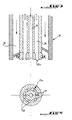
- the precalciner properly says consists of a combustion chamber 20 connected by a sheath 21 to a reaction chamber 22. the latter being connected via a valve 23 to the junction box 3 from which the fumes II entering the reaction chamber 22 to its part lower.
- the reaction chamber 22 communicates with an afterburner pipe 24, swan neck shaped, emerging in a cyclone 25 allowing the recovery of the precalcined product in 12.
- the hot air F enters the precalciner 2 by a pipe 26 which is subdivided into three pipes, namely a first conduit 27 opening tangentially in the combustion chamber 20, a second duct 28 emerging through a volute 29 in said chamber 20. at the level of a burner 30 equipping this chamber, and a third conduit 31 opening into the pipe 24 for connecting the reaction chamber 22 to cyclone 25.
- first conduit 27 and the volute 29 print the same direction of rotation with hot air in the combustion chamber 20.
- the burner 30 mounted in the upper part of the combustion 20, in the axis of the volute 29, essentially comprises three concentric envelopes that define from inside to outside: a passage central 34 for an additional fuel which can be heavy fuel or recovery solvents, a channel 35 ensuring the injection of pressurized air: and another channel 36 through which a pulverized fuel such as than coal, and transported by a gas flow such as air.
- the air under pressure is injected into the combustion chamber 20 by a special head 35a comprising a plurality of nozzles 37 of axes tangent to a hyperboloid of revolution inducing a rotational movement of the same direction that the one coming out of the volute 29 and that the one coming out of the first conduit 27.
- the assymptotic cone of the hyperboloid of revolution in question presents an angle to the vertex between about 3 and 90 °, and preferably between 10 and 45 °.
- high speed injection fumes 11 thanks to the valve 23, associated with a low average speed of the reducing smoke-gas mixture in this room optimizes the kinetics reduction reaction by increasing turbulence in said room.
- This result is obtained in using a smoke speed between 20 and 40 m / sec., for an average speed in the reaction 22 from 5 to 20 m / sec.
- the speed smoke 11 is between 25 and 35 m / sec, and the average speed in chamber 22 is included between 10 and 15 m / sec.
- hot air injection by line 31 in post-combustion line 24 it also suitable for obtaining a homogeneous mixture of air oxidant and residual reducing fumes. This is assured using a hot air injection speed between 20 and 40 m / sec, and an injection angle greater than 60 °.
- the average speed, downstream of the injection point of the pipe 31, that is to say in the pipe afterburner 24, must allow a residence time sufficient while maintaining a good level of turbulence. Therefore, this average speed is chosen between 8 and 24 m / sec, and preferably between 12 and 18 m / sec.
- the speed fuel injection was 15 m / sec
- the speed of smoke 11 was 24 m / sec
- the speed average of the mixture in the reaction chamber 22 was 11.5 m / sec
- the speed in the post-combustion pipe 24 was 14 m / sec.
Landscapes
- Engineering & Computer Science (AREA)
- Chemical & Material Sciences (AREA)
- Ceramic Engineering (AREA)
- Thermal Sciences (AREA)
- Materials Engineering (AREA)
- Structural Engineering (AREA)
- Organic Chemistry (AREA)
- Mechanical Engineering (AREA)
- General Engineering & Computer Science (AREA)
- Physics & Mathematics (AREA)
- Curing Cements, Concrete, And Artificial Stone (AREA)
- Furnace Details (AREA)
- Coloring Foods And Improving Nutritive Qualities (AREA)
- Feeding, Discharge, Calcimining, Fusing, And Gas-Generation Devices (AREA)
- Manufacture And Refinement Of Metals (AREA)
- Fertilizers (AREA)
- Solid-Sorbent Or Filter-Aiding Compositions (AREA)
- Steroid Compounds (AREA)
- Medicines Containing Material From Animals Or Micro-Organisms (AREA)
- Cleaning And De-Greasing Of Metallic Materials By Chemical Methods (AREA)
- Mechanical Treatment Of Semiconductor (AREA)
- Catalysts (AREA)
- Silicates, Zeolites, And Molecular Sieves (AREA)
Claims (13)
- Anlage zum Vorkalzinieren von Mineralstoffen in pulverförmiger vorgeheizter Gestalt (8), insbesondere von Zementklinkern, mit einem den vorgeheizten Stoff (8) empfangenden Vorkalzinator (2), der mit Heissluft (F) von einer mit einem Kühler (5) verbundenen und zumindest in zwei Leitungselemente (27, 28, 31) unterteilten Leitung (10, 26) gespeist wird, wobei der Vorkalzinator (2) im wesentlichen einerseits aus einer, reduzierende Gase bildenden Brennkammer (20) mit einem auf dem oberen Teil, in der Achse einer den Brenner (30) umschliessenden Spirale, der Brennkammer (20) angeordneten Brennstoffbrenner (30) besteht, die Brennkammer (20) mit aus dem Kühler (5) durch ein erstes Leitungselement, genannt zweite Leitung (28), kommender Heissluft gespeist wird, das in der Höhe des besagten Brenners (30) angeschlossen ist und in die Brennkammer (20) durch die Spirale (29) so mündet, dass der so eingeblasenen Heissluft eine Drehbewegung in einer ersten Richtung verliehen wird, andererseits aus einer Reaktionskammer (22) durch Reduktion von Stickstoffoxiden, die mit der besagten Brennkammer (20) kommuniziert (21) und mit aus einem Brennofen (4) kommenden Rauchen (11), die reich an Stickstoffoxiden sind, gespeist wird, wobei diese Rauche die Reaktionskammer durchfliessen und mit Heissluft gemischt werden, die durch ein zweites Leitungselement, genannt dritte Heissluftleitung (31) zugeführt wird, das aus der Unterteilung der besagten Heissluftleitung (10, 26) resultiert, und schliesslich aus einem Zyklon (25) zur Stoffabscheidung, der mit der Reaktionskammer (22) durch eine Nachbrennleitung (24) verbunden ist, in welche die dritte Heissluftleitung (31) mündet, dadurch gekennzeichnet, dass sie ein drittes Leitungselement, genannt erste Leitung (27) enthält, das aus der Unterteilung der besagten Heissluftleitung (10, 26) résultiert und das tangential in die besagte Brennkammer (20) mündet, um der von der ersten Leitung (27) eingespritzten Heissluft (J) eine Drehbewegung in einer ersten Richtung zu verleihen, dass die Nachbrennleitung (24) schwanenhalsförmig ausgebildet ist, dass dieser Brenner (30) ein Brenner für pulverförmige Brennstoffe ist, wie Kohle oder ein Gemisch aus Petrolkoks und pulverförmiger Kohle, und Zusatzbrennstoff, und dass die dritte Heissluftleitung (31) derart in die Anschlussleitung (24) zum Zyklon (25) mündet, derart, dass der aus dieser dritten Leitung (31) ausfliessende Heissluftstrom mit den aus der Reaktionskammer (22) austretenden Rauchen (11) einen Winkel (I) zwischen 140° und 160° bildet.
- Anlage gemäss Anspruch 1, dadurch gekennzeichnet, dass die an Stickstoffoxiden reiche Rauche in die Reaktionskammer (22) über ein Regelventil (23) eingespritzt werden, während wenigstens ein Ventil (32) die zu den drei vorgenannten Leitungen (27, 28, 31) gelangende Heissluftdurchsatzmenge einstellt, und dass die zweite vorgenannte Leitung (28) und die dritte vorgenannte Leitung (31) jeweils mit wenigstens einem Regelventil (33) versehen sind.
- Anlage gemäss Anspruch 1 oder 2, dadurch gekennzeichnet, dass der vorgenannte Brenner (30) durch wenigstens drei konzentrische Hüllen gebildet wird die, von der Innenseite nach der Aussenseite hin, einen zentralen Durchgang (34), einen Kanal (35) und einen weiteren Kanal (36) definieren, die jeweils einen Zusatzbrennstoff, Druckluft und einen zerstäubten, mittels eines gasförmigen Stroms, wie Luft, beförderten Brennstoff befördern.
- Anlage gemäss Anspruch 3, dadurch gekennzeichnet, dass die Druckluft in die Brennkammer (20) durch eine Mehrzahl von Düsen (37) eingeblasen wird, deren Achsen ein Umdrehungshyperboloid tangieren, wobei eine Drehbewegung in derselben Richtung wie die der jeweils aus der Spirale (29) und der vorgenannten ersten Leitung (27) austretenden Heissluft verliehen wird.
- Anlage gemäss Anspruch 4, dadurch gekennzeichnet, dass der asymptotische Konus des Umdrehungshyperboloids einen zwischen 3° und 90° und in bevorzugter Weise einen zwischen 10° und 45° liegenden kegelspitzen Winkel hat.
- Anlage gemäss Anspruch 4 oder 5, dadurch gekennzeichnet, dass die Mehrzahl der Düsen (37) zu einem Sonderkopf (35a) des Brenners (30) gehören.
- Verfahren zum Vorkalzinieren von Mineralstoffen in pulverförmiger Gestalt, insbesondere von Zementklinkern, das darin besteht, den Stoff vorzuheizen (1) und den vorgeheizten Stoff (8) in einem Vorkalzinator (2) zu kalzinieren, der mit aus dem Kühler (5) kommender Heissluft (F, 26) gespeist wird, durch eine in drei Ströme (27, 28, 31) aufgeteilte Leitung (10, 26) und einerseits, eine als Generator reduzierender Gase wie CO und H2 funktionierende Brennkammer (20) aufweist, die von einem ersten, tangential an die Brennkammer (20) angeschlossenen Strom (27) gespeist wird, um der Heissluft (J) dieses ersten Stromes (27) eine Drehbewegung zu verleihen, und durch einen zweiten Strom (28) dieser Heissluft (F), eintreffend auf der Höhe eines Brenners (30) von zerstäubtem Brennstoff und von Zusatzbrennstoff, der auf der Brennkammer (20) angebracht ist und in die Brennkammer (20) durch eine Spirale (29) hindurch mündet, und der der Heissluft dieselbe Drehbewegung erteilt wie die des ersten Stromes (27), wobei eine Reaktionskammer (22) durch Reduzierung von Stickstoffoxiden, mit der Brennkammer (20) kommuniziert und mit an Stickstoffoxiden reichen, aus einem Brennofen (4) kommenden Rauchen (11), gespeist wird, und andererseits, einen Zyklon (25) zur Stoffabscheidung aufweist, der an die Reaktionskammer (22) durch eine Anschlussleitung (24) angeschlossen ist, in welche der dritte Strom (31) der vorgenannten Heissluft (F) eingespritzt wird, und wo eine Nachbrennung stattfindet, wobei der besagte erste Strom (J, 27) der besagten Heissluft (F) 40% bis 85% des gesamten Heissluftstroms (F) beträgt, wohingegen der besagte zweite Strom (28) 5% bis 30% des gesamten Heissluftstroms (F) beträgt, und der dritte Strom (31) 10% bis 40% des gesamten Heissluftstroms (F) beträgt, wobei diese Heissluftdurchsätze jeweils durch Regulierung (32, 33) dieser Flüsse erhalten werden, und die Maximaltemperatur am Ausgang des Brenners (30) durch Regulierung (33) des Heissluftdurchsatzes des zweiten Stromes (28) auf einen Wert, der geringer als die Schmelztemperatur der Mineralstoffe ist, aufrechterhalten wird, wobei der dritte Strom (31) so in die Anschlussleitung (24) mündet, dass der dritte Strom, mit den aus der Reaktionskammer (22) austretenden Gasen, einen Winkel (I) zwischen 140° und 160° bildet.
- Verfahren gemäss Anspruch 7, dadurch gekennzeichnet, dass der erste Heissluftstrom (J, 27) 50% bis 75% des Gesamtheissluftstromes (F, 26) darstellt, der zweite Heissluftstrom (28) 5% bis 30% des Gesamtheissluftstromes (F, 26) darstellt, und der dritte Heissluftstrom (31) 15% bis 30% des besagten Gesamtheissluftstromes (F, 26) darstellt.
- Verfahren gemäss einem der Ansprüche 7 bis 8, dadurch gekennzeichnet, dass durch Regulierung (23), die Einspritzgeschwindigkeit der Rauche (11), die reich an Stickstoffoxiden sind, in der Reaktionskammer (22) zwischen 20 m/s und 40 m/s liegt, vorzugsweise zwischen 25 m/s und 35 m/s, die mittlere Geschwindigkeit der Rauche in der Reaktionskammer (22) zwischen 5 m/s und 20 m/s liegt und vorzugsweise zwischen 10 m/s und 15 m/s beträgt, und die mittlere Geschwindigkeit der Rauche in der vorgenannten Anschlussleitung (24) stromabwärts der Einspritzung des dritten Luftstromes (31) zwischen 8 m/s und 24 m/s und in bevorzugter Weise zwischen 12 m/s und 18 m/s beträgt.
- Verfahren gemäss einem der Ansprüche 7 bis 9, dadurch gekennzeichnet, dass die axiale Einspritzgeschwindigkeit des pulverförmigen Brennstoffs (9) in der Brennkammer (20) zwischen 10 m/s und 30 m/s und in bevorzugter Weise zwischen 10 m/s und 18 m/s beträgt, während die vom Brenner (30) gelieferte Druckluft (35) in die besagte Brennkammer (20) mit einer Geschwindigkeit über 75 m/s und in bevorzugter Weise über 150 m/s mittels eines Kopfes (35a), der eine Mehrzahl von Düsen (37) aufweist, eingeblasen wird, deren Achsen ein Umdrehungshyperboloid tangieren, das einen asymptotischen Konus aufweist, mit einem zwischen 3° und 90°, und in bevorzugter Weise zwischen 10° und 45° liegenden kegelspitzen Winkel.
- Verfahren gemäss Anspruch 10, dadurch gekennzeichnet, dass der besagte Kopf (35a) zum Einspitzen von Druckluft (35) der besagten eingespritzten Druckluft eine Drehbewegung in derselben Drehrichtung wie der erste Strom (27) verleiht, und dass die Drehbewegung des zweiten Stromes (28) in der Spirale (29), die Drehbewegung des ersten Stromes (27), die Drehbewegung der unter Druck eingespritzten Luft (35) zusammen einen die Flamme in der Brennkammer (20) stabilisierenden Wirbel bilden.
- Verfahren gemäss einem der Ansprüche 7 bis 11, dadurch gekennzeichnet, dass der Brennstoff (36) zerstäubter Brennstoff ist, wie Kohle oder eine Mischung aus Petrolkoks und zerstäubter Kohle.
- Verfahren gemäss einem der Ansprüche 7 bis 12, dadurch gekennzeichnet, dass der Zusatzbrennstoff (34) schweres Heizöl oder rückgewonnene Lösungsmittel sind.
Applications Claiming Priority (2)
| Application Number | Priority Date | Filing Date | Title |
|---|---|---|---|
| FR9206579A FR2691790B1 (fr) | 1992-05-29 | 1992-05-29 | Installation et procede de precalcination de matieres minerales quelconques. |
| FR9206579 | 1992-05-29 |
Publications (3)
| Publication Number | Publication Date |
|---|---|
| EP0572322A1 EP0572322A1 (de) | 1993-12-01 |
| EP0572322B1 EP0572322B1 (de) | 1996-02-07 |
| EP0572322B2 true EP0572322B2 (de) | 2001-10-24 |
Family
ID=9430290
Family Applications (1)
| Application Number | Title | Priority Date | Filing Date |
|---|---|---|---|
| EP93401355A Expired - Lifetime EP0572322B2 (de) | 1992-05-29 | 1993-05-27 | Anlage und Verfahren zur Prekalzination von alle mineralen Gut |
Country Status (11)
| Country | Link |
|---|---|
| US (2) | US5364265A (de) |
| EP (1) | EP0572322B2 (de) |
| JP (1) | JP3559843B2 (de) |
| AT (1) | ATE134033T1 (de) |
| AU (1) | AU657052B2 (de) |
| CA (1) | CA2097245C (de) |
| DE (1) | DE69301499T3 (de) |
| DK (1) | DK0572322T4 (de) |
| ES (1) | ES2108241T5 (de) |
| FR (1) | FR2691790B1 (de) |
| GR (1) | GR3019864T3 (de) |
Families Citing this family (16)
| Publication number | Priority date | Publication date | Assignee | Title |
|---|---|---|---|---|
| FR2691790B1 (fr) * | 1992-05-29 | 1997-09-19 | Cle | Installation et procede de precalcination de matieres minerales quelconques. |
| FR2736910B1 (fr) * | 1995-07-21 | 1997-10-10 | Technip Cie | Installation et procede de calcination de matieres minerales avec emission reduite d'oxydes d'azote |
| DE19649922A1 (de) * | 1996-12-02 | 1998-06-04 | Krupp Polysius Ag | Verfahren und Vorrichtung zur Wärmebehandlung von feinkörnigem Gut |
| CA2240442C (en) * | 1996-02-14 | 2003-09-16 | F.L. Smidth & Co. A/S | Method for reducing nox emission from a kiln plant |
| US6488765B1 (en) | 1997-07-30 | 2002-12-03 | Cemex, Inc. | Oxygen enrichment of cement kiln system combustion |
| DK174194B1 (da) * | 1998-02-04 | 2002-09-09 | Smidth & Co As F L | Ovnanlæg, samt fremgangsmåde til fremstilling af cement |
| US6309210B1 (en) * | 1999-03-16 | 2001-10-30 | L'air Liquide, Societe Anonyme Pour L'etude Et, L'exploitation Des Procedes Georges Claude | Kiln universal oxygen enrichment |
| DE19920143A1 (de) * | 1999-05-03 | 2000-11-09 | Kloeckner Humboldt Wedag | Verfahren und Anlage zur thermischen Behandlung von mehlförmigen Rohmaterialien |
| AU6994400A (en) * | 1999-09-24 | 2001-04-30 | F.L. Smidth & Co A/S | Method for reducing nox emission from a plant for manufacturing cement clinker |
| DK174307B1 (da) * | 2000-08-24 | 2002-12-02 | Smidth & Co As F L | Fremgangsmåde samt anlæg til fremstilling af cementklinker. |
| US6672865B2 (en) * | 2000-09-11 | 2004-01-06 | Cadence Enviromental Energy, Inc. | Method of mixing high temperature gases in mineral processing kilns |
| US7229281B2 (en) * | 2000-09-11 | 2007-06-12 | Cadence Environmental Energy, Inc. | Method of mixing high temperature gases in mineral processing kilns |
| JP4998639B1 (ja) * | 2011-07-25 | 2012-08-15 | 三菱マテリアル株式会社 | セメント製造設備 |
| DE102012110653B3 (de) * | 2012-11-07 | 2014-05-15 | Thyssenkrupp Resource Technologies Gmbh | Zementherstellungsanlage |
| FR3010405A1 (fr) * | 2013-09-10 | 2015-03-13 | Lafarge Sa | Installation et procede de precalcination |
| CN105903340A (zh) * | 2016-04-26 | 2016-08-31 | 安徽海螺建材设计研究院 | 干法水泥窑高活性CaO提取接口的选择方法 |
Family Cites Families (7)
| Publication number | Priority date | Publication date | Assignee | Title |
|---|---|---|---|---|
| DE2541564C2 (de) * | 1975-09-18 | 1983-01-20 | Klöckner-Humboldt-Deutz AG, 5000 Köln | Vorrichtung zur Wärmebehandlung von feinkörnigem Gut |
| US4050882A (en) * | 1976-11-04 | 1977-09-27 | Allis-Chalmers Corporation | Dual variable orifice for reinforced preheater |
| DE3237689A1 (de) * | 1982-10-12 | 1984-04-12 | Krupp Polysius Ag, 4720 Beckum | Anlage zur waermebehandlung von feinkoernigem gut |
| DE3520058A1 (de) * | 1985-06-04 | 1986-12-04 | O & K Orenstein & Koppel Ag, 1000 Berlin | Verfahren zur waermebehandlung von feinkoernigem gut |
| DE3538707A1 (de) * | 1985-10-31 | 1987-05-07 | Kloeckner Humboldt Deutz Ag | Verfahren und vorrichtung zur thermischen behandlung von mehlfoermigen rohmaterialien |
| DE3817357A1 (de) * | 1988-05-20 | 1989-11-30 | Krupp Polysius Ag | Verfahren und vorrichtung zur waermebehandlung von feinkoernigem gut |
| FR2691790B1 (fr) * | 1992-05-29 | 1997-09-19 | Cle | Installation et procede de precalcination de matieres minerales quelconques. |
-
1992
- 1992-05-29 FR FR9206579A patent/FR2691790B1/fr not_active Expired - Fee Related
-
1993
- 1993-05-26 US US08/067,357 patent/US5364265A/en not_active Expired - Lifetime
- 1993-05-27 ES ES93401355T patent/ES2108241T5/es not_active Expired - Lifetime
- 1993-05-27 DE DE69301499T patent/DE69301499T3/de not_active Expired - Lifetime
- 1993-05-27 DK DK93401355T patent/DK0572322T4/da active
- 1993-05-27 AT AT93401355T patent/ATE134033T1/de active
- 1993-05-27 EP EP93401355A patent/EP0572322B2/de not_active Expired - Lifetime
- 1993-05-28 CA CA002097245A patent/CA2097245C/en not_active Expired - Lifetime
- 1993-05-28 JP JP12726693A patent/JP3559843B2/ja not_active Expired - Lifetime
- 1993-05-31 AU AU39938/93A patent/AU657052B2/en not_active Ceased
-
1994
- 1994-08-01 US US08/283,646 patent/US5454714A/en not_active Expired - Lifetime
-
1996
- 1996-05-07 GR GR960401250T patent/GR3019864T3/el unknown
Also Published As
| Publication number | Publication date |
|---|---|
| FR2691790A1 (fr) | 1993-12-03 |
| DE69301499D1 (de) | 1996-03-21 |
| ATE134033T1 (de) | 1996-02-15 |
| ES2108241T3 (es) | 1997-12-16 |
| AU3993893A (en) | 1993-12-02 |
| AU657052B2 (en) | 1995-02-23 |
| CA2097245C (en) | 2005-12-20 |
| FR2691790B1 (fr) | 1997-09-19 |
| JP3559843B2 (ja) | 2004-09-02 |
| EP0572322A1 (de) | 1993-12-01 |
| ES2108241T5 (es) | 2002-04-16 |
| US5454714A (en) | 1995-10-03 |
| DE69301499T2 (de) | 1996-09-19 |
| JPH06206742A (ja) | 1994-07-26 |
| DK0572322T3 (da) | 1996-07-08 |
| US5364265A (en) | 1994-11-15 |
| GR3019864T3 (en) | 1996-08-31 |
| CA2097245A1 (en) | 1993-11-30 |
| DE69301499T3 (de) | 2002-07-11 |
| DK0572322T4 (da) | 2002-02-18 |
| EP0572322B1 (de) | 1996-02-07 |
Similar Documents
| Publication | Publication Date | Title |
|---|---|---|
| EP0572322B2 (de) | Anlage und Verfahren zur Prekalzination von alle mineralen Gut | |
| CN1024043C (zh) | 起动固体燃料电站锅炉并确保其燃料燃烧过程的方法和装置 | |
| EP3724144B1 (de) | Klinkerproduktionsanlage und verfahren zur klinkerherstellung in einer solchen anlage | |
| EP0754924B1 (de) | Vorrichtung und Verfahren zum Kalzinieren von Rohmehl mit verminderter Stickoxydemission | |
| CH629886A5 (fr) | Procede de combustion d'un combustible carbone. | |
| KR0151166B1 (ko) | 재순환 및 플러그 흐름 연소방법 | |
| WO2013056524A1 (zh) | 一种富氧环境下的等离子无油点火系统 | |
| EP0065436B1 (de) | Verfahren und Vorrichtungen zur Herstellung von Zementklinker nach dem Trockenverfahren | |
| EP1031790B1 (de) | Verbesserungen an Flachflammenbrennern | |
| KR20100118954A (ko) | 바이오매스용 중앙 공기제트 버너 | |
| EP1065461B1 (de) | In der Zementherstellung anwendbarer Verbrennungsprozess | |
| FR2795716A1 (fr) | Procede de calcination d'un materiau a base de minerai | |
| CN213334398U (zh) | 一种危险废物热解焚烧系统 | |
| EP0076175B1 (de) | Verfahren und Vorrichtung zum Kalzinieren puderförmiger Mineralstoffe, insbesondere in der Zementindustrie | |
| US5803936A (en) | Reactor for the continuous production of a flammable gas | |
| CN101233377A (zh) | 用于煅烧具有低NOx排放物的材料的方法 | |
| CN223983700U (zh) | 一种低碳烧结系统 | |
| CN105605584B (zh) | 一种在水泥窑中利用富氧处置固废的方法 | |
| FR2487814A1 (fr) | Procede et dispositif pour le traitement thermique de matieres a faible granulometrie | |
| CA1201409A (en) | Reduction of nitrogen oxide emissions from calciners | |
| FR2803022A1 (fr) | Procede d'installation d'alimentation en air d'un bruleur a combustible solide et pulverise | |
| CA1079065A (en) | Cement calcining apparatus | |
| US20250207858A1 (en) | Method for operating a burner of a rotary kiln | |
| CN118922679A (zh) | 操作回转炉燃烧器的方法 | |
| FR2659134A1 (fr) | Procede et appareil pour le traitement thermique de matieres minerales pulverulentes. |
Legal Events
| Date | Code | Title | Description |
|---|---|---|---|
| PUAI | Public reference made under article 153(3) epc to a published international application that has entered the european phase |
Free format text: ORIGINAL CODE: 0009012 |
|
| AK | Designated contracting states |
Kind code of ref document: A1 Designated state(s): AT BE CH DE DK ES FR GB GR IE IT LI LU MC NL PT SE |
|
| 17P | Request for examination filed |
Effective date: 19931123 |
|
| 17Q | First examination report despatched |
Effective date: 19941025 |
|
| GRAA | (expected) grant |
Free format text: ORIGINAL CODE: 0009210 |
|
| AK | Designated contracting states |
Kind code of ref document: B1 Designated state(s): AT BE CH DE DK ES FR GB GR IE IT LI LU MC NL PT SE |
|
| REF | Corresponds to: |
Ref document number: 134033 Country of ref document: AT Date of ref document: 19960215 Kind code of ref document: T |
|
| REG | Reference to a national code |
Ref country code: IE Ref legal event code: FG4D Free format text: 67209 |
|
| REF | Corresponds to: |
Ref document number: 69301499 Country of ref document: DE Date of ref document: 19960321 |
|
| ITF | It: translation for a ep patent filed | ||
| REG | Reference to a national code |
Ref country code: ES Ref legal event code: BA2A |
|
| REG | Reference to a national code |
Ref country code: CH Ref legal event code: PUE Owner name: CLE TRANSFER- TECHNIP Ref country code: CH Ref legal event code: NV Representative=s name: BOVARD AG PATENTANWAELTE |
|
| GBT | Gb: translation of ep patent filed (gb section 77(6)(a)/1977) |
Effective date: 19960513 |
|
| NLS | Nl: assignments of ep-patents |
Owner name: TECHNIP, SOCIETE ANONYME |
|
| REG | Reference to a national code |
Ref country code: DK Ref legal event code: T3 |
|
| REG | Reference to a national code |
Ref country code: GR Ref legal event code: FG4A Free format text: 3019864 |
|
| SC4A | Pt: translation is available |
Free format text: 960503 AVAILABILITY OF NATIONAL TRANSLATION |
|
| REG | Reference to a national code |
Ref country code: PT Ref legal event code: PC4A Free format text: TECHNIP FR Effective date: 19960612 |
|
| PLBQ | Unpublished change to opponent data |
Free format text: ORIGINAL CODE: EPIDOS OPPO |
|
| PLBI | Opposition filed |
Free format text: ORIGINAL CODE: 0009260 |
|
| REG | Reference to a national code |
Ref country code: GB Ref legal event code: 732E |
|
| PLBQ | Unpublished change to opponent data |
Free format text: ORIGINAL CODE: EPIDOS OPPO |
|
| PLBI | Opposition filed |
Free format text: ORIGINAL CODE: 0009260 |
|
| 26 | Opposition filed |
Opponent name: FCB Effective date: 19961008 Opponent name: F.L. SMIDTH & CO. A/S Effective date: 19961007 |
|
| PLBF | Reply of patent proprietor to notice(s) of opposition |
Free format text: ORIGINAL CODE: EPIDOS OBSO |
|
| 26 | Opposition filed |
Opponent name: KRUPP POLYSIUS AG Effective date: 19961024 Opponent name: FCB Effective date: 19961008 Opponent name: F.L. SMIDTH & CO. A/S Effective date: 19961007 |
|
| BECH | Be: change of holder |
Free format text: 960207 *TECHNIP |
|
| NLR1 | Nl: opposition has been filed with the epo |
Opponent name: F.L. SMIDTH & CO. A/S |
|
| NLR1 | Nl: opposition has been filed with the epo |
Opponent name: KRUPP POLYSIUS AG Opponent name: F.L. SMIDTH & CO. A/S |
|
| PLBF | Reply of patent proprietor to notice(s) of opposition |
Free format text: ORIGINAL CODE: EPIDOS OBSO |
|
| PLBQ | Unpublished change to opponent data |
Free format text: ORIGINAL CODE: EPIDOS OPPO |
|
| PLAB | Opposition data, opponent's data or that of the opponent's representative modified |
Free format text: ORIGINAL CODE: 0009299OPPO |
|
| PLBF | Reply of patent proprietor to notice(s) of opposition |
Free format text: ORIGINAL CODE: EPIDOS OBSO |
|
| R26 | Opposition filed (corrected) |
Opponent name: F.L. SMIDTH & CO. A/S * 961008 FCB * 961024 KRUPP Effective date: 19961007 |
|
| NLR1 | Nl: opposition has been filed with the epo |
Opponent name: KRUPP POLYSIUS AG Opponent name: F.L. SMIDTH & CO. A/S |
|
| RAP2 | Party data changed (patent owner data changed or rights of a patent transferred) |
Owner name: TECHNIP |
|
| REG | Reference to a national code |
Ref country code: ES Ref legal event code: FG2A Ref document number: 2108241 Country of ref document: ES Kind code of ref document: T3 |
|
| NLT2 | Nl: modifications (of names), taken from the european patent patent bulletin |
Owner name: TECHNIP |
|
| REG | Reference to a national code |
Ref country code: FR Ref legal event code: TP |
|
| RDAH | Patent revoked |
Free format text: ORIGINAL CODE: EPIDOS REVO |
|
| APAC | Appeal dossier modified |
Free format text: ORIGINAL CODE: EPIDOS NOAPO |
|
| APAE | Appeal reference modified |
Free format text: ORIGINAL CODE: EPIDOS REFNO |
|
| APAC | Appeal dossier modified |
Free format text: ORIGINAL CODE: EPIDOS NOAPO |
|
| PLBQ | Unpublished change to opponent data |
Free format text: ORIGINAL CODE: EPIDOS OPPO |
|
| PLAB | Opposition data, opponent's data or that of the opponent's representative modified |
Free format text: ORIGINAL CODE: 0009299OPPO |
|
| R26 | Opposition filed (corrected) |
Opponent name: F.L. SMIDTH & CO. A/S * 19961008 FCB * 19961024 KR Effective date: 19961007 |
|
| NLR1 | Nl: opposition has been filed with the epo |
Opponent name: KRUPP POLYSIUS AG Opponent name: F.L. SMIDTH & CO. A/S |
|
| APAC | Appeal dossier modified |
Free format text: ORIGINAL CODE: EPIDOS NOAPO |
|
| PLAW | Interlocutory decision in opposition |
Free format text: ORIGINAL CODE: EPIDOS IDOP |
|
| PUAH | Patent maintained in amended form |
Free format text: ORIGINAL CODE: 0009272 |
|
| STAA | Information on the status of an ep patent application or granted ep patent |
Free format text: STATUS: PATENT MAINTAINED AS AMENDED |
|
| 27A | Patent maintained in amended form |
Effective date: 20011024 |
|
| AK | Designated contracting states |
Kind code of ref document: B2 Designated state(s): AT BE CH DE DK ES FR GB GR IE IT LI LU MC NL PT SE |
|
| REG | Reference to a national code |
Ref country code: CH Ref legal event code: AEN Free format text: MAINTIEN DU BREVET DONT L'ETENDUE A ETE MODIFIEE |
|
| NLR2 | Nl: decision of opposition | ||
| REG | Reference to a national code |
Ref country code: GB Ref legal event code: IF02 |
|
| REG | Reference to a national code |
Ref country code: DK Ref legal event code: T4 |
|
| GBTA | Gb: translation of amended ep patent filed (gb section 77(6)(b)/1977) | ||
| NLR3 | Nl: receipt of modified translations in the netherlands language after an opposition procedure | ||
| REG | Reference to a national code |
Ref country code: ES Ref legal event code: DC2A Kind code of ref document: T5 Effective date: 20020123 |
|
| REG | Reference to a national code |
Ref country code: GR Ref legal event code: EP Ref document number: 20020400328 Country of ref document: GR |
|
| PGFP | Annual fee paid to national office [announced via postgrant information from national office to epo] |
Ref country code: DK Payment date: 20020527 Year of fee payment: 10 |
|
| PGFP | Annual fee paid to national office [announced via postgrant information from national office to epo] |
Ref country code: SE Payment date: 20030409 Year of fee payment: 11 |
|
| PG25 | Lapsed in a contracting state [announced via postgrant information from national office to epo] |
Ref country code: DK Free format text: LAPSE BECAUSE OF NON-PAYMENT OF DUE FEES Effective date: 20031201 |
|
| REG | Reference to a national code |
Ref country code: DK Ref legal event code: EBP |
|
| PGFP | Annual fee paid to national office [announced via postgrant information from national office to epo] |
Ref country code: MC Payment date: 20040503 Year of fee payment: 12 |
|
| PG25 | Lapsed in a contracting state [announced via postgrant information from national office to epo] |
Ref country code: SE Free format text: LAPSE BECAUSE OF NON-PAYMENT OF DUE FEES Effective date: 20040528 |
|
| EUG | Se: european patent has lapsed | ||
| PG25 | Lapsed in a contracting state [announced via postgrant information from national office to epo] |
Ref country code: MC Free format text: LAPSE BECAUSE OF NON-PAYMENT OF DUE FEES Effective date: 20050531 |
|
| APAH | Appeal reference modified |
Free format text: ORIGINAL CODE: EPIDOSCREFNO |
|
| REG | Reference to a national code |
Ref country code: CH Ref legal event code: PFA Owner name: TECHNIP Free format text: TECHNIP#TOUR TECHNIP, LA DEFENCE 6, 170, PLACE HENRI REGNAULT#COURBEVOIE (FR) -TRANSFER TO- TECHNIP#TOUR TECHNIP, LA DEFENCE 6, 170, PLACE HENRI REGNAULT#COURBEVOIE (FR) |
|
| PGFP | Annual fee paid to national office [announced via postgrant information from national office to epo] |
Ref country code: NL Payment date: 20120425 Year of fee payment: 20 Ref country code: DE Payment date: 20120514 Year of fee payment: 20 Ref country code: CH Payment date: 20120523 Year of fee payment: 20 Ref country code: LU Payment date: 20120417 Year of fee payment: 20 Ref country code: IE Payment date: 20120427 Year of fee payment: 20 |
|
| PGFP | Annual fee paid to national office [announced via postgrant information from national office to epo] |
Ref country code: BE Payment date: 20120531 Year of fee payment: 20 Ref country code: GR Payment date: 20120427 Year of fee payment: 20 Ref country code: FR Payment date: 20120618 Year of fee payment: 20 Ref country code: GB Payment date: 20120521 Year of fee payment: 20 |
|
| PGFP | Annual fee paid to national office [announced via postgrant information from national office to epo] |
Ref country code: IT Payment date: 20120522 Year of fee payment: 20 |
|
| PGFP | Annual fee paid to national office [announced via postgrant information from national office to epo] |
Ref country code: ES Payment date: 20120524 Year of fee payment: 20 |
|
| PGFP | Annual fee paid to national office [announced via postgrant information from national office to epo] |
Ref country code: PT Payment date: 20120418 Year of fee payment: 20 |
|
| PGFP | Annual fee paid to national office [announced via postgrant information from national office to epo] |
Ref country code: AT Payment date: 20120424 Year of fee payment: 20 |
|
| REG | Reference to a national code |
Ref country code: DE Ref legal event code: R071 Ref document number: 69301499 Country of ref document: DE |
|
| REG | Reference to a national code |
Ref country code: DE Ref legal event code: R071 Ref document number: 69301499 Country of ref document: DE |
|
| BE20 | Be: patent expired |
Owner name: *TECHNIP Effective date: 20130527 |
|
| REG | Reference to a national code |
Ref country code: CH Ref legal event code: PL |
|
| REG | Reference to a national code |
Ref country code: PT Ref legal event code: MM4A Free format text: MAXIMUM VALIDITY LIMIT REACHED Effective date: 20130527 |
|
| REG | Reference to a national code |
Ref country code: NL Ref legal event code: V4 Effective date: 20130527 |
|
| REG | Reference to a national code |
Ref country code: GB Ref legal event code: PE20 Expiry date: 20130526 |
|
| REG | Reference to a national code |
Ref country code: AT Ref legal event code: MK07 Ref document number: 134033 Country of ref document: AT Kind code of ref document: T Effective date: 20130527 |
|
| PG25 | Lapsed in a contracting state [announced via postgrant information from national office to epo] |
Ref country code: DE Free format text: LAPSE BECAUSE OF EXPIRATION OF PROTECTION Effective date: 20130528 Ref country code: GB Free format text: LAPSE BECAUSE OF EXPIRATION OF PROTECTION Effective date: 20130526 |
|
| REG | Reference to a national code |
Ref country code: ES Ref legal event code: FD2A Effective date: 20130808 |
|
| PG25 | Lapsed in a contracting state [announced via postgrant information from national office to epo] |
Ref country code: PT Free format text: LAPSE BECAUSE OF EXPIRATION OF PROTECTION Effective date: 20130604 |
|
| REG | Reference to a national code |
Ref country code: GR Ref legal event code: MA Ref document number: 20020400328 Country of ref document: GR Effective date: 20130528 |
|
| PG25 | Lapsed in a contracting state [announced via postgrant information from national office to epo] |
Ref country code: ES Free format text: LAPSE BECAUSE OF EXPIRATION OF PROTECTION Effective date: 20130528 |
|
| PG25 | Lapsed in a contracting state [announced via postgrant information from national office to epo] |
Ref country code: IE Free format text: LAPSE BECAUSE OF EXPIRATION OF PROTECTION Effective date: 20130527 |