EP0572322B2 - Installation and process for the precalcination of any mineral matters - Google Patents
Installation and process for the precalcination of any mineral matters Download PDFInfo
- Publication number
- EP0572322B2 EP0572322B2 EP93401355A EP93401355A EP0572322B2 EP 0572322 B2 EP0572322 B2 EP 0572322B2 EP 93401355 A EP93401355 A EP 93401355A EP 93401355 A EP93401355 A EP 93401355A EP 0572322 B2 EP0572322 B2 EP 0572322B2
- Authority
- EP
- European Patent Office
- Prior art keywords
- hot air
- duct
- flow
- combustion chamber
- burner
- Prior art date
- Legal status (The legal status is an assumption and is not a legal conclusion. Google has not performed a legal analysis and makes no representation as to the accuracy of the status listed.)
- Expired - Lifetime
Links
- 238000000034 method Methods 0.000 title claims abstract description 14
- 229910052500 inorganic mineral Inorganic materials 0.000 title claims abstract description 12
- 239000011707 mineral Substances 0.000 title claims abstract description 12
- 238000009434 installation Methods 0.000 title description 15
- MWUXSHHQAYIFBG-UHFFFAOYSA-N nitrogen oxide Inorganic materials O=[N] MWUXSHHQAYIFBG-UHFFFAOYSA-N 0.000 claims abstract description 54
- 238000002485 combustion reaction Methods 0.000 claims abstract description 42
- 238000006243 chemical reaction Methods 0.000 claims abstract description 25
- 239000004568 cement Substances 0.000 claims abstract description 4
- 238000010304 firing Methods 0.000 claims abstract 3
- 239000000446 fuel Substances 0.000 claims description 23
- 239000000463 material Substances 0.000 claims description 20
- 238000002347 injection Methods 0.000 claims description 15
- 239000007924 injection Substances 0.000 claims description 15
- 239000007789 gas Substances 0.000 claims description 11
- 239000003245 coal Substances 0.000 claims description 6
- 239000000203 mixture Substances 0.000 claims description 6
- 239000000571 coke Substances 0.000 claims description 3
- 238000000926 separation method Methods 0.000 claims description 3
- 238000001354 calcination Methods 0.000 claims description 2
- 239000002904 solvent Substances 0.000 claims description 2
- 238000010438 heat treatment Methods 0.000 claims 1
- 238000002844 melting Methods 0.000 claims 1
- 230000008018 melting Effects 0.000 claims 1
- 230000000087 stabilizing effect Effects 0.000 claims 1
- 239000003517 fume Substances 0.000 abstract description 12
- 238000004519 manufacturing process Methods 0.000 abstract description 2
- 238000006722 reduction reaction Methods 0.000 description 10
- 238000010411 cooking Methods 0.000 description 5
- OKTJSMMVPCPJKN-UHFFFAOYSA-N Carbon Chemical compound [C] OKTJSMMVPCPJKN-UHFFFAOYSA-N 0.000 description 4
- 229910052799 carbon Inorganic materials 0.000 description 4
- 239000000779 smoke Substances 0.000 description 4
- IJGRMHOSHXDMSA-UHFFFAOYSA-N Atomic nitrogen Chemical compound N#N IJGRMHOSHXDMSA-UHFFFAOYSA-N 0.000 description 2
- CPLXHLVBOLITMK-UHFFFAOYSA-N Magnesium oxide Chemical compound [Mg]=O CPLXHLVBOLITMK-UHFFFAOYSA-N 0.000 description 2
- 230000001939 inductive effect Effects 0.000 description 2
- 239000007800 oxidant agent Substances 0.000 description 2
- 230000001590 oxidative effect Effects 0.000 description 2
- 238000011084 recovery Methods 0.000 description 2
- 239000007787 solid Substances 0.000 description 2
- 235000008733 Citrus aurantifolia Nutrition 0.000 description 1
- 235000011941 Tilia x europaea Nutrition 0.000 description 1
- 240000008042 Zea mays Species 0.000 description 1
- PNEYBMLMFCGWSK-UHFFFAOYSA-N aluminium oxide Inorganic materials [O-2].[O-2].[O-2].[Al+3].[Al+3] PNEYBMLMFCGWSK-UHFFFAOYSA-N 0.000 description 1
- 239000003638 chemical reducing agent Substances 0.000 description 1
- 230000001627 detrimental effect Effects 0.000 description 1
- 238000010586 diagram Methods 0.000 description 1
- 229910000514 dolomite Inorganic materials 0.000 description 1
- 239000010459 dolomite Substances 0.000 description 1
- 230000000694 effects Effects 0.000 description 1
- -1 for example Substances 0.000 description 1
- 230000004927 fusion Effects 0.000 description 1
- 239000008240 homogeneous mixture Substances 0.000 description 1
- 239000004571 lime Substances 0.000 description 1
- 239000000395 magnesium oxide Substances 0.000 description 1
- 229910052757 nitrogen Inorganic materials 0.000 description 1
- 239000002006 petroleum coke Substances 0.000 description 1
- 239000000843 powder Substances 0.000 description 1
- 230000002829 reductive effect Effects 0.000 description 1
- 230000006641 stabilisation Effects 0.000 description 1
- 238000011105 stabilization Methods 0.000 description 1
Images


Classifications
-
- C—CHEMISTRY; METALLURGY
- C04—CEMENTS; CONCRETE; ARTIFICIAL STONE; CERAMICS; REFRACTORIES
- C04B—LIME, MAGNESIA; SLAG; CEMENTS; COMPOSITIONS THEREOF, e.g. MORTARS, CONCRETE OR LIKE BUILDING MATERIALS; ARTIFICIAL STONE; CERAMICS; REFRACTORIES; TREATMENT OF NATURAL STONE
- C04B7/00—Hydraulic cements
- C04B7/36—Manufacture of hydraulic cements in general
- C04B7/43—Heat treatment, e.g. precalcining, burning, melting; Cooling
-
- F—MECHANICAL ENGINEERING; LIGHTING; HEATING; WEAPONS; BLASTING
- F27—FURNACES; KILNS; OVENS; RETORTS
- F27B—FURNACES, KILNS, OVENS OR RETORTS IN GENERAL; OPEN SINTERING OR LIKE APPARATUS
- F27B7/00—Rotary-drum furnaces, i.e. horizontal or slightly inclined
- F27B7/20—Details, accessories or equipment specially adapted for rotary-drum furnaces
- F27B7/2016—Arrangements of preheating devices for the charge
- F27B7/2025—Arrangements of preheating devices for the charge consisting of a single string of cyclones
- F27B7/2033—Arrangements of preheating devices for the charge consisting of a single string of cyclones with means for precalcining the raw material
Definitions
- the first object of the present invention is a precalcination installation for any mineral material, such as, for example, cement clinker, lime, alumina, magnesia, or dolomite.
- the invention according to its first aspect, relates to a installation as defined by the preamble of claim 1.
- Mineral precalcination facilities comprising in particular a precalciner essentially consisting of a combustion chamber supplied with hot air, a reaction chamber communicating with the combustion chamber and supplied with fumes rich in nitrogen oxides from a cooking oven, and a cyclone allowing the separation of the material and connected to the reaction chamber by a pipe.
- US Pat. No. 4,014,641 recommends injecting air therefrom cooler.
- the present invention essentially aims to propose an installation and a precalcination process which does not have the drawbacks mentioned above and which allows a reduction of approximately 30 to 70% of the nitrogen oxides generated by the oven, thanks to the efficiency of the combustion chamber which produces a maximum of reducing gas CO, H 2 for a minimum of unburnt carbon, and which causes the partial reduction Fe +++ to Fe ++ in mineral matter, unburnt carbon being in the form of a highly reactive coke.
- the fumes rich in nitrogen oxides are injected into the reaction chamber via a valve adjustment, while at least one valve regulates the flow of hot air reaching the three aforementioned conduits, and that the second and third aforementioned conduits are each provided with at least one adjustment valve.
- the aforementioned burner may consist of at least three casings concentric which from inside to outside respectively convey make-up fuel, pressurized air and atomized fuel and transported by a gas flow.
- pressurized air is advantageously injected into the combustion chamber by nozzles tangent to a hyperboloid of revolution inducing a rotational movement in the same direction as that of the hot air.
- the asymptote cone of the hyperboloid of revolution has an angle at the top between 3 and 90 °.
- This invention also relates to a process for the precalcination of mineral matter any in powder form, as defined in claim 7.
- the first flow represents from 50 to 75% of the total hot air flow
- the second flow from 15 to 30%
- the third flow from 15 to 30%.
- This process is also advantageously such that the speed of injection of the fumes rich in nitrogen oxides in the reaction chamber is between 20 and 40 m / sec.,
- the average speed of the films in the reaction chamber is between 5 and 20 m / sec., preferably 10 to 15 m / sec. and speed average smoke in the aforementioned pipe downstream of the injection of the third air flow is between 8 and 24 m / sec., preferably 12 to 18 m / sec.
- the axial speed of fuel injection sprayed into the combustion chamber is between 10 and 30 m / sec, and preferably between 10 and 18 m / sec. while the pressurized air supplied by the burner is injected into said chamber a speed greater than 75 m / sec, and preferably greater at 150 m / sec.
- the pulverized material is fed in 6 to the preheater 1 in which the hot fumes 7 originating from the precalciner 2 preheats said material.
- the hot material 8 leaving the preheater 1 is partially calcined in precalciner 2 by a energy input from one part of the build-up of a fuel 9 with preheated air arriving by a pipe 10 of the cooler 5 and on the other hand, fumes 11 from the oven 4 through a box of junction 3.
- the precalcined material 12 is fed to the oven 4 at through the junction box 3 to finish cooking by an energy contribution from the combustion of a fuel 13 with preheated air 14 from the cooler 5.
- the cooked product 10 (calcined, clinkerized or melted depending on the material) leaving the oven 4 is cooled in the cooler 5 and discharged at 15.
- At least part of the hot air recovered from the cooler 5, such as that passing through line 10, is used as combustion air in the precalciner 2. and as shown by the arrow F in FIG. 2.
- the arrow G in Figure 1 illustrates the excess air hot from cooler 5 and intended for others uses.
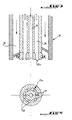
- the precalciner properly says consists of a combustion chamber 20 connected by a sheath 21 to a reaction chamber 22. the latter being connected via a valve 23 to the junction box 3 from which the fumes II entering the reaction chamber 22 to its part lower.
- the reaction chamber 22 communicates with an afterburner pipe 24, swan neck shaped, emerging in a cyclone 25 allowing the recovery of the precalcined product in 12.
- the hot air F enters the precalciner 2 by a pipe 26 which is subdivided into three pipes, namely a first conduit 27 opening tangentially in the combustion chamber 20, a second duct 28 emerging through a volute 29 in said chamber 20. at the level of a burner 30 equipping this chamber, and a third conduit 31 opening into the pipe 24 for connecting the reaction chamber 22 to cyclone 25.
- first conduit 27 and the volute 29 print the same direction of rotation with hot air in the combustion chamber 20.
- the burner 30 mounted in the upper part of the combustion 20, in the axis of the volute 29, essentially comprises three concentric envelopes that define from inside to outside: a passage central 34 for an additional fuel which can be heavy fuel or recovery solvents, a channel 35 ensuring the injection of pressurized air: and another channel 36 through which a pulverized fuel such as than coal, and transported by a gas flow such as air.
- the air under pressure is injected into the combustion chamber 20 by a special head 35a comprising a plurality of nozzles 37 of axes tangent to a hyperboloid of revolution inducing a rotational movement of the same direction that the one coming out of the volute 29 and that the one coming out of the first conduit 27.
- the assymptotic cone of the hyperboloid of revolution in question presents an angle to the vertex between about 3 and 90 °, and preferably between 10 and 45 °.
- high speed injection fumes 11 thanks to the valve 23, associated with a low average speed of the reducing smoke-gas mixture in this room optimizes the kinetics reduction reaction by increasing turbulence in said room.
- This result is obtained in using a smoke speed between 20 and 40 m / sec., for an average speed in the reaction 22 from 5 to 20 m / sec.
- the speed smoke 11 is between 25 and 35 m / sec, and the average speed in chamber 22 is included between 10 and 15 m / sec.
- hot air injection by line 31 in post-combustion line 24 it also suitable for obtaining a homogeneous mixture of air oxidant and residual reducing fumes. This is assured using a hot air injection speed between 20 and 40 m / sec, and an injection angle greater than 60 °.
- the average speed, downstream of the injection point of the pipe 31, that is to say in the pipe afterburner 24, must allow a residence time sufficient while maintaining a good level of turbulence. Therefore, this average speed is chosen between 8 and 24 m / sec, and preferably between 12 and 18 m / sec.
- the speed fuel injection was 15 m / sec
- the speed of smoke 11 was 24 m / sec
- the speed average of the mixture in the reaction chamber 22 was 11.5 m / sec
- the speed in the post-combustion pipe 24 was 14 m / sec.
Landscapes
- Engineering & Computer Science (AREA)
- Chemical & Material Sciences (AREA)
- Ceramic Engineering (AREA)
- Thermal Sciences (AREA)
- Materials Engineering (AREA)
- Structural Engineering (AREA)
- Organic Chemistry (AREA)
- Mechanical Engineering (AREA)
- General Engineering & Computer Science (AREA)
- Physics & Mathematics (AREA)
- Curing Cements, Concrete, And Artificial Stone (AREA)
- Furnace Details (AREA)
- Coloring Foods And Improving Nutritive Qualities (AREA)
- Feeding, Discharge, Calcimining, Fusing, And Gas-Generation Devices (AREA)
- Manufacture And Refinement Of Metals (AREA)
- Fertilizers (AREA)
- Solid-Sorbent Or Filter-Aiding Compositions (AREA)
- Steroid Compounds (AREA)
- Medicines Containing Material From Animals Or Micro-Organisms (AREA)
- Cleaning And De-Greasing Of Metallic Materials By Chemical Methods (AREA)
- Mechanical Treatment Of Semiconductor (AREA)
- Catalysts (AREA)
- Silicates, Zeolites, And Molecular Sieves (AREA)
Abstract
Description
La présente invention a pour premier objet une installation de précalcination de matières minérales quelconques, tels que par exemple, clinker de ciment, chaux, alumine, magnésie, ou dolomie.The first object of the present invention is a precalcination installation for any mineral material, such as, for example, cement clinker, lime, alumina, magnesia, or dolomite.
Plus précisément, l'invention, selon son premier aspect, concerne une
installation telle que définie par le préambule de la revendication 1.More specifically, the invention, according to its first aspect, relates to a
installation as defined by the preamble of
Elle vise également un procédé de précalcination de telles matières.It also relates to a process for precalcination of such materials.
On a déjà proposé des installations de précalcination de matières minérales comprenant notamment un précalcinateur essentiellement constitué d'une chambre de combustion alimentée en air chaud, d'une chambre de réaction communiquant avec la chambre de combustion et alimentée en fumées riches en oxydes d'azote provenant d'un four de cuisson, et d'un cyclone permettant la séparation de la matière et raccordé à la chambre de réaction par une conduite.Mineral precalcination facilities have already been proposed comprising in particular a precalciner essentially consisting of a combustion chamber supplied with hot air, a reaction chamber communicating with the combustion chamber and supplied with fumes rich in nitrogen oxides from a cooking oven, and a cyclone allowing the separation of the material and connected to the reaction chamber by a pipe.
Il est possible de faire fonctionner ce genre d'installation en marche réductrice de façon à éliminer au moins partiellement les oxydes d'azote. Cependant, la réduction des oxydes d'azote est limitée, car, dans ces installations, on génère, en marche réductrice, beaucoup de carbone imbrûlé qui est pratiquement inactif pour la réduction des oxydes d'azote. En outre, ce carbone imbrûlé est difficile à réoxyder ultérieurement et est néfaste au bon fonctionnement du four de cuisson.It is possible to operate this type of installation in reduction mode so as to at least partially remove the nitrogen oxides. However, the reduction of nitrogen oxides is limited, because in these installations, in reduction gear, a lot of unburnt carbon which is practically inactive for the reduction of nitrogen oxides. Furthermore, this unburnt carbon is difficult to re-oxidize later and is detrimental to the proper functioning of the cooking.
Une installation conforme au préambule de la revendication 1 est décrite dans le
brevet US 4 014 641. Ce brevet antérieur concerne une installation dans laquelle
les gaz chargés en oxydes d'azote issus d'un four de calcination sont mélangés,
en vue de leur réduction, avec des gaz réducteurs issus d'une chambre de
combustion à comburant déficitaire.An installation in accordance with the preamble of
Pour éviter le rejet dans l'atmosphère du mélange gazeux ainsi obtenu, encore trop réducteur, le brevet US 4 014 641 préconise d'y injecter de l'air issu d'un refroidisseur.To prevent the gas mixture thus obtained from being released into the atmosphere, further too reductive, US Pat. No. 4,014,641 recommends injecting air therefrom cooler.
Dans ce contexte, la présente invention a essentiellement pour but de proposer une installation et un procédé de précalcination ne présentant pas les inconvénients cités ci-dessus et permettant une réduction d'environ 30 à 70 % des oxydes d'azote générés par le four, grâce à l'efficacité de la chambre de combustion qui produit un maximum de gaz réducteur CO, H2 pour un minimum de carbone imbrûlé, et qui provoque la réduction partielle Fe+++ en Fe++ dans les matières minérales, le carbone imbrûlé se trouvant sous la forme d'un coke fortement réactif.In this context, the present invention essentially aims to propose an installation and a precalcination process which does not have the drawbacks mentioned above and which allows a reduction of approximately 30 to 70% of the nitrogen oxides generated by the oven, thanks to the efficiency of the combustion chamber which produces a maximum of reducing gas CO, H 2 for a minimum of unburnt carbon, and which causes the partial reduction Fe +++ to Fe ++ in mineral matter, unburnt carbon being in the form of a highly reactive coke.
A cet effet, l'installation de l'invention, par ailleurs conforme à la définition
générique qu'en donne le préambule de la revendication 1, est principalement
définie par les caractéristiques spécifiques énoncées dans la partie caractérisante
de cette même revendication 1.To this end, the installation of the invention, moreover conforms to the definition
Generic which the preamble of
Selon un mode de réalisation préféré de cette installation, les fumées riches en oxydes d'azote sont injectées dans la chambre de réaction via une vanne de réglage, tandis qu'au moins une vanne règle le débit d'air chaud parvenant aux trois conduits précités, et que le deuxième et troisième conduits précités sont chacun munis d'au moins une vanne de réglage.According to a preferred embodiment of this installation, the fumes rich in nitrogen oxides are injected into the reaction chamber via a valve adjustment, while at least one valve regulates the flow of hot air reaching the three aforementioned conduits, and that the second and third aforementioned conduits are each provided with at least one adjustment valve.
Le brûleur précité peut être constitué par au moins trois enveloppes concentriques qui depuis l'intérieur vers l'extérieur véhiculent respectivement un combustible d'appoint, de l'air sous pression et un combustible pulvérisé et transporté par un flux gazeux.The aforementioned burner may consist of at least three casings concentric which from inside to outside respectively convey make-up fuel, pressurized air and atomized fuel and transported by a gas flow.
On précisera encore que l'air sous pression est avantageusement injecté dans la chambre de combustion par des buses tangentes à un hyperboloïde de révolution induisant un mouvement de rotation de même sens que celui de l'air chaud.It will also be specified that the pressurized air is advantageously injected into the combustion chamber by nozzles tangent to a hyperboloid of revolution inducing a rotational movement in the same direction as that of the hot air.
Le cône asymptote de l'hyperboloïde de révolution possède un angle au sommet compris entre 3 et 90°.The asymptote cone of the hyperboloid of revolution has an angle at the top between 3 and 90 °.
Cette invention vise encore un procédé de précalcination de matières minérales quelconques sous forme pulvérulente, tel que défini dans la revendication 7.This invention also relates to a process for the precalcination of mineral matter any in powder form, as defined in claim 7.
De préférence le premier flux représente de 50 à 75 % du flux d'air chaud total, le deuxième flux de 15 à 30 %, et le troisième flux de 15 à 30 %. Preferably the first flow represents from 50 to 75% of the total hot air flow, the second flow from 15 to 30%, and the third flow from 15 to 30%.
Ce procédé est encore avantageusement tel que la vitesse d'injection des fumées riches en oxydes d'azote dans la chambre de réaction est comprise entre 20 et 40 m/sec., la vitesse moyenne des filmées dans la chambre de réaction est comprise entre 5 et 20 m/sec., de préférence 10 à 15 m/sec. et la vitesse moyenne des fumées dans la conduite précitée en aval de l'injection du troisième flux d'air est comprise entre 8 et 24 m/sec., de préférence 12 à 18 m/sec.This process is also advantageously such that the speed of injection of the fumes rich in nitrogen oxides in the reaction chamber is between 20 and 40 m / sec., The average speed of the films in the reaction chamber is between 5 and 20 m / sec., preferably 10 to 15 m / sec. and speed average smoke in the aforementioned pipe downstream of the injection of the third air flow is between 8 and 24 m / sec., preferably 12 to 18 m / sec.
On précisera encore ici que la vitesse axiale d'injection du combustible pulvérisé dans la chambre de combustion est comprise entre 10 et 30 m/sec, et de préférence entre 10 et 18 m/sec. tandis que l'air sous pression fourni par le brûleur est injecté dans ladite chambre à une vitesse supérieure à 75 m/sec, et de préférence supérieure à 150 m/sec.It will also be specified here that the axial speed of fuel injection sprayed into the combustion chamber is between 10 and 30 m / sec, and preferably between 10 and 18 m / sec. while the pressurized air supplied by the burner is injected into said chamber a speed greater than 75 m / sec, and preferably greater at 150 m / sec.
Mais d'autres caractéristiques et avantages de l'invention
apparaítront mieux dans la description détaillée
qui suit et se réfère aux dessins annexés, donnés uniquement
à titre d'exemple, et dans lesquels :
En se reportant à la figure 1, on voit une installation
de cuisson de matières minérales dans laquelle la matière
alimentée à l'état pulvérisé traverse successivement
un préchauffeur 1, un précalcinateur 2, un four de
cuisson 4, et un refroidisseur 5.Referring to Figure 1, we see an installation
mineral material baking in which the material
fed in the sprayed state passes successively
a
La matière pulvérisée est alimentée en 6 au préchauffeur
1 dans lequel les fumées chaudes 7 issues du
précalcinateur 2 préchauffent ladite matière.The pulverized material is fed in 6 to the
La matière chaude 8 sortant du préchauffeur 1 est
partiellement calcinée dans le précalcinateur 2 par un
apport d'énergie provenant d'une part de la conmbustion
d'un combustible 9 avec de l'air préchauffé arrivant par
une conduite 10 du refroidisseur 5 et d'autre part, des
fumées 11 provenant du four 4 à travers une boíte de
jonction 3.The hot material 8 leaving the
La matière précalcinée 12 est alimentée au four 4 à
travers la boíte de jonction 3 pour terminer la cuisson par
un apport d'énergie provenant de la combustion d'un
combustible 13 avec de l'air préchauffé 14 provenant du
refroidisseur 5. Le produit cuit 10 (calciné, clinkérisé ou
fondu suivant le matériau) sortant du four 4 est refroidi
dans le refrodisseur 5 et évacué en 15.The
Au moins une partie de l'air chaud récupéré au refroidisseur
5, tel que celui passant dans la conduite 10,
est utilisée comme air de combustion au précalcinateur
2. et comme matérialisé par la flèche F sur la figure 2.At least part of the hot air recovered from the
La flèche G sur la figure 1 illustre l'excédent d'air
chaud sortant du refroidisseur 5 et destiné à d'autres
usages.The arrow G in Figure 1 illustrates the excess air
hot from
Sur la figure 2, on voit que le précalcinateur proprement
dit se compose d'une chambre de combustion 20
reliée par une gaine 21 à une chambre de réaction 22.
cette dernière étant reliée par l'intermédiaire d'une vanne
23 à la boíte de jonction 3 d'où sortent les fumées II
pénétrant dans la chambre de réaction 22 à sa partie
inférieure. A sa partie supérieure, la chambre de réaction
22 communique avec une conduite 24 de postcombustion,
en forme de col de cygne, débouchant dans un cyclone
25 permettant la récupération du produit précalciné
en 12.In Figure 2, we see that the precalciner properly
says consists of a
Suivant une caractéristique essentielle de l'invention,
l'air chaud F pénètre dans le précalcinateur 2 par
une conduite 26 qui se subdivise en trois conduits, à savoir
un premier conduit 27 débouchant tangentiellement
dans la chambre de combustion 20, un deuxième conduit
28 débouchant à travers une volute 29 dans ladite
chambre 20. au niveau d'un brûleur 30 équipant cette
chambre, et d'un troisième conduit 31 débouchant dans
la conduite 24 de raccordement de la chambre de réaction
22 au cyclone 25.According to an essential characteristic of the invention,
the hot air F enters the precalciner 2 by
a
On observera ici que le premier conduit 27 et la volute
29 impriment à l'air chaud un même sens de rotation
dans la chambre de combustion 20.It will be observed here that the
Le flux d'air chaud sortant du troisième conduit 31,
et comme cela est illustré par des flèches, fait avec les
fumées sortant de la chambre de réaction 22, et comme
cela est matérialisé par la flèche 1 un angle supérieur à
60°. Cet angle sera avantageusement compris entre 140
et 160°.The flow of hot air leaving the
On a montré en 32 un ensemble de vannes de réglage
du débit d'air chaud parvenant d'une part via le
premier conduit 27 à la chambre de combustion 20 (flèche
J), et d'autre part aux deuxième et troisième conduits
28, 31. Dans chacun de ces conduits 28, 31, est installée
une vanne de réglage 33.We have shown in 32 a set of control valves
of the hot air flow arriving on the one hand via the
En se reportant maintenant à la figure 3, on voit que
le brûleur 30 monté en partie haute de la chambre de
combustion 20, dans l'axe de la volute 29, comprend essentiellement
trois enveloppes concentriques et qui définissent
depuis l'intérieur vers l'extérieur : un passage
central 34 pour un combustible d'appoint qui peut être
du fuel lourd ou des solvants de récupération, un canal
35 assurant l'injection d'air sous pression : et un autre
canal 36 par où peut sortir un combustible pulvérisé tel
que charbon, et transporté par un flux gazeux tel que air.Referring now to Figure 3, we see that
the
En se reportant à la figure 4, on voit que l'air sous
pression est injecté dans la chambre de combustion 20
par une tête spéciale 35a comportant une pluralité de
buses 37 d'axes tangents à un hyperboloïde de révolution
induisant un mouvement de rotation de même sens
que celui sortant de la volute 29 et que celui sortant du
premier conduit 27.Referring to Figure 4, we see that the air under
pressure is injected into the
On précisera ici que le cône assymptote de l'hyperboloïde de révolution en question présente un angle au sommet compris entre environ 3 et 90°, et de préférence compris entre 10 et 45°.It will be specified here that the assymptotic cone of the hyperboloid of revolution in question presents an angle to the vertex between about 3 and 90 °, and preferably between 10 and 45 °.
Ayant ainsi décrit l'installation de précalcination selon cette invention. on expliquera maintenant dans ce qui suit son fonctionnement en même temps que ses nombreux avantages. Pour obtenir l'effet recherché, c'est-à-dire une très forte diminution de la teneur en oxydes d'azote des fumées sortant du four de cuisson 4, il convient d'intervenir sur plusieurs paramètres, et notamment d'adopter une combinaison spécifique de paramètres. Having thus described the precalcination installation according to this invention. we will now explain in what follows its operation at the same time as its numerous benefits. To achieve the desired effect, that is to say a very strong decrease in the oxide content nitrogen from the fumes leaving the baking oven 4, it should intervene on several parameters, and in particular to adopt a specific combination of parameters.
Tout d'abord, au niveau de la chambre de combustion
20, qui doit fonctionner comme générateur de gaz
réducteur, il faut stabiliser la flamme du brûleur 30 naturellement
instable dans ces conditions, et c'est pourquoi,
selon l'invention, on utilise, pour la chambre de
combustion 20 un vortex de stabilisation de flamme
constitué par la combinaison de la volute 29 avec la tête
spéciale 35a d'injection d'air sous pression, et avec l'injection
tangentielle d'air chaud en J. De plus, le contrôle
du débit d'air dans le deuxième conduit 28 grâce à la
vanne 33 permet d'obtenir une température maximum
en sortie du brûleur 30, sans pour autant provoquer la
fusion des matières minérales. Ces dispositions permettent
avantageusement d'éviter les carbones imbrûlés à
l'état solide et de favoriser la production de gaz réducteur
acheminé dans la chambre de réaction 22 via la conduite
21.First, at the
Au niveau de cette chambre, l'injection à grande vitesse
des fumées 11 grâce à la vanne 23, associée à
une vitesse moyenne faible du mélange fumées-gaz réducteur
dans cette chambre permet d'optimiser la cinétique
de réaction de réduction par accroissement des turbulences
dans ladite chambre. Ce résultat est obtenu en
utilisant une vitesse de fumées comprise entre 20 et 40
m/sec., pour une vitesse moyenne dans la chambre de
réaction 22 de 5 à 20 m/sec. Préférentiellement, la vitesse
des fumées 11 est comprise entre 25 et 35 m/sec, et
la vitesse moyenne dans la chambre 22 est comprise
entre 10 et 15 m/sec.At this chamber, high speed injection
fumes 11 thanks to the
Par ailleurs, au niveau de l'injection d'air chaud par
la conduite 31 dans la conduite postcombustion 24, il
convient aussi d'obtenir un mélange homogène de l'air
oxydant et des fumées réductrices résiduelles. Ceci est
assuré en utilisant une vitesse d'injection d'air chaud
comprise entre 20 et 40 m/sec, et un angle d'injection
supérieur à 60°. De plus, la vitesse moyenne, en aval du
point d'injection du conduit 31, c'est-à-dire dans la conduite
postcombustion 24, doit permettre un temps de séjour
suffisant tout en maintenant un bon niveau de turbulence.
C'est pourquoi, cette vitesse moyenne est
choisie entre 8 et 24 m/sec, et de préférence entre 12 et
18 m/sec.Furthermore, at the level of hot air injection by
C'est ainsi qu'en choisissant par exemple d'envoyer
65% de l'air chaud par le premier conduit 27 dans la
chambre de combustion 20, 15% d'air chaud par le conduit
28, dans la volute 29, et 20% d'air chaud dans la
conduite 24 via le conduit 31, il est possible, en utilisant
comme combustible dans le brûleur 30 un mélange de
coke de pétrole et de charbon pulvérisé d'obtenir une
réduction de la teneur en oxydes d'azote de 47% sur les
fumées riches en oxydés d'azote provenant du four 4,
tout en maintenant le taux d'imbrülés solides dans les
matières sortant du cyclone 25 à moins de 4% de la totalité
du combustible envoyé par le brûleur 30 à la chambre
de combustion. Dans cet exemple particulier, la vitesse
d'injection du combustible était de 15 m/sec, la vitesse
de s fumées 11 était de 24 m/sec, la vitesse
moyenne du mélange dans la chambre de réaction 22
était de 11,5 m/sec, et la vitesse dans la conduite post-combustion
24 était de 14 m/sec.This is how, for example, by choosing to send
65% of the hot air through the
On a donc réalisé suivant l'invention une installation et un procédé de précalcination procurant des avantages exceptionnels notamment au regard de la réduction des émissions d'oxydes d'azote qui sont néfastes pour l'environnement.An installation was therefore carried out according to the invention and a precalcination process providing advantages exceptional especially with regard to the reduction nitrogen oxide emissions which are harmful to the environment.
Bien entendu, l'invention n'est nullement limitée au mode de réalisation décrit et illustré qui n'a été donné qu'à titre d'exemple.Of course, the invention is in no way limited to described and illustrated embodiment which has not been given as an example.
Claims (13)
- Equipment for the precalcination of pre-heated mineral materials in powdery form (8), in particular cement clinker, comprising a precalciner (2) receiving the pre-heated material (8), fed with hot air (F) by means of a duct (10, 26) connected to a cooler (5) and subdivised into at least two duct elements (27, 28, 31), the precalciner (2) consisting essentially, on the one hand, of a combustion chamber (20) which forms a reducing gas generator and with a fuel burner (30) mounted onto the combustion chamber (20) at a top portion thereof in axis of a scroll (29) surrounding the burner (30), the combustion chamber (20) being fed with hot air coming from the cooler (5) by means of a first duct element, a so-called second duct (28) connected at the level of said burner (30) and opening into the combustion chamber (20) through the scroll (29) in order to impart therein, to the hot air as injected, a rotary motion according to a first direction, on the other hand, of a reaction chamber (22) for reduction of nitrogen oxides, communicating (21) with said combustion chamber (20) and fed (3) with smokes (11) rich in nitrogen oxides coming from a firing furnace (4), these smokes passing through the reaction chamber and being mixed with hot air as dispatched by a second duct element, a so-called third hot air duct (31), coming from the subdivision of said hot air duct (10, 26) and, lastly, a material separation cyclone (25) connected to said reaction chamber (22) by means of a post-combustion duct (24) in which opens the third hot air duct (31), characterized in that it comprises a third duct element, a so-called first duct (27), coming from the subdivision of said hot air duct (10, 26), and opening tangentially into said combustion chamber (20) in order to impart to the hot air (J) as injected by this first duct (27), a rotary motion according to the first direction, in that the post-combustion duct (24) is swan-neck shaped, in that said burner (30) is a burner of powdered fuel, such as powdered coal or a powdered mixture of petrol coke and coal, and make-up supply fuel, and in that the third hot air duct (31) opens into the duct (24) for connection to the cyclone (25), so that the hot air flow coming from this third duct (31) makes an angle (I) comprised between 140° and 160° with the smokes (11) coming from the reaction chamber (22).
- Equipement according to claim 1, characterized in that the smokes rich in nitrogen oxides are injected into the reaction chamber (22) via a control valve (23), whereas at least one valve (32) controls the hot air flow (F) reaching the three above-mentioned ducts (27, 28, 31), and in that said second duct (28) and said third duct (31) are each one provided with at least one control valve (33).
- Equipement according to claim 1 or 2, characterized in that the above-mentioned burner (30) is constituted by at least three concentric envelopes defining, from the inside to the outside, a central passage (34), a channel (35) and an other channel (36), respectively, which conveys a make-up supply fuel, an air under pressure and a powdered fuel carried by a gaseous flow such as air, respectively.
- Equipment according to claim 3, characterized in that the air under pressure is injected into the combustion chamber (20) by means of a plurality of nozzles (37) of axes which are tangent to an hyperboloid of revolution which induces a rotary motion with a same direction as that of the hot air coming from the scroll (29) and said first duct (27), respectively.
- Equipement according to claim 4, characterized in that the asymptotic cone of the hyperboloid of revolution has an apex angle comprised between 3° and 90°, and preferably between 10° and 45°.
- Equipement according to claim 4 or 5, characterized in that the plurality of nozzles (37) belongs to a particular head (35a) of the burner (30).
- Method for the precalcination of mineral materials in powdery form, in particular cement clinker, consisting in pre-heating (1) the material and calcining the pre-heated material (8) in a precalciner (2) fed with hot air (F, 26) from a cooler (5) by means of a duct (10, 26) which is subdivised into three flows (27, 28, 31) and comprises, on the one hand, a combustion chamber (20) operating as a generator of reducing gas such as CO and H2 and fed by a first flow (27) connected tangentially to the combustion chamber (20), in order to impart a rotary motion to the hot air (J) of this first flow (27), and by a second flow (28) of said hot air (F) coming at the level of a powdered fuel and make-up supply fuel burner (30), mounted onto the combustion chamber (20) and opening into the combustion chamber (20) through a scroll (29), and imparting to the hot air the same rotation direction as that of the first flow (27), a reaction chamber (22) for reduction of nitrogen oxides which communicates with the combustion chamber (20) and is fed with smokes (11) rich in nitrogen oxides coming (3) from a firing furnace (4) and, on the other hand, a material separation cyclone (25) connected to the reaction chamber (22) by means of a connecting duct (24) into which is injected the third flow (31) of said hot air (F) and in which is produced a post-combustion, said first flow (J,27) of said hot air (F) representing from 40% to 85% of the total hot air flow (F), whereas said second flow (28) represents from 5% to 30% of the total hot air flow (F) and the third flow (31) represents from 10% to 40% of the total hot air flow (F), these hot air flow rates being respectively obtained by controlling (32, 33) the flows, and the maximum output temperature of the burner (30) being maintained by controlling (33) the hot air flow rate of said second flow (28) at a value which is lower than the melting temperature of the mineral materials, the third flow (31) opening into the connecting duct (24), so that this third flow makes an angle (I) comprised between 140° and 160° with the smokes (11) coming from the reaction chamber (22).
- Method according the claim 7, characterized in that said first hot air flow (J, 27) represents from 50% to 75% of the total hot air flow (F, 26), said second hot air flow (28) represents from 5% to 30% of the total hot air flow (F, 26) and said third hot air flow (31) represents from 15% to 30% of said total hot air flow (F,26).
- Method according to one of claims 7 to 8, characterized in that, by means of a control (23), the speed of injection of the smokes (11) rich in nitrogen oxides into the reaction chamber (22) is comprised between 20 m/s and 40 m/s, preferably between 25 m/s and 35 m/s, the mean speed of the smokes in the reaction chamber (22) is comprised between 5 m/s and 20 m/s, preferably between 10 m/s and 15 m/s, and the mean speed of the smokes in the above-mentioned connecting duct (24) downstream the injection of said third air flow (31) is comprised between 8 m/s and 24 m/s, preferably between 12 m/s and 18 m/s.
- Method according to one of claims 7 to 9, characterized in that the axial speed of injection of the powdered fuel (9) into the combustion chamber (20) is comprised between 10 m/s and 30 m/s and preferably between 10 m/s and 18 m/s, whereas the air under pressure (35), supplied by the burner (30), is injected into said combustion chamber (20) at a speed which is higher than 75 m/s and preferably higher than 150 m/s by means of a head (35a) comprising a plurality of nozzles (37) of axes which are tangent to an hyperboloid of revolution having an asympotic cone of an apex angle comprised between 3° and 90°, and preferably between 10° and 45°.
- Method according to claim 10, characterized in that said head (35a) for injecting air under pressure (35) induces, on the air which is injected under pressure, a rotary motion with the same direction as that of the first flow (27), and in that the rotary motion of the second flow (28) in the scroll (29), the rotary motion of the first flow (27), and the rotary motion of the air which is injected under pressure (35) creates, in combination, a vortex for stabilizing the flame in the combustion chamber (20).
- Method according to one of claims 7 to 11, characterized in that the fuel (36) is a powdered fuel such as powdered coal or a powdered mixture of petrol coke and coal.
- Method according to one of claims 7 to 12, characterized in that the make-up supply fuel (34) is an heavy fuel or recuperation solvents.
Applications Claiming Priority (2)
| Application Number | Priority Date | Filing Date | Title |
|---|---|---|---|
| FR9206579A FR2691790B1 (en) | 1992-05-29 | 1992-05-29 | INSTALLATION AND METHOD FOR PRE-CALCINATION OF ANY MINERAL MATERIAL. |
| FR9206579 | 1992-05-29 |
Publications (3)
| Publication Number | Publication Date |
|---|---|
| EP0572322A1 EP0572322A1 (en) | 1993-12-01 |
| EP0572322B1 EP0572322B1 (en) | 1996-02-07 |
| EP0572322B2 true EP0572322B2 (en) | 2001-10-24 |
Family
ID=9430290
Family Applications (1)
| Application Number | Title | Priority Date | Filing Date |
|---|---|---|---|
| EP93401355A Expired - Lifetime EP0572322B2 (en) | 1992-05-29 | 1993-05-27 | Installation and process for the precalcination of any mineral matters |
Country Status (11)
| Country | Link |
|---|---|
| US (2) | US5364265A (en) |
| EP (1) | EP0572322B2 (en) |
| JP (1) | JP3559843B2 (en) |
| AT (1) | ATE134033T1 (en) |
| AU (1) | AU657052B2 (en) |
| CA (1) | CA2097245C (en) |
| DE (1) | DE69301499T3 (en) |
| DK (1) | DK0572322T4 (en) |
| ES (1) | ES2108241T5 (en) |
| FR (1) | FR2691790B1 (en) |
| GR (1) | GR3019864T3 (en) |
Families Citing this family (16)
| Publication number | Priority date | Publication date | Assignee | Title |
|---|---|---|---|---|
| FR2691790B1 (en) * | 1992-05-29 | 1997-09-19 | Cle | INSTALLATION AND METHOD FOR PRE-CALCINATION OF ANY MINERAL MATERIAL. |
| FR2736910B1 (en) * | 1995-07-21 | 1997-10-10 | Technip Cie | PLANT AND METHOD FOR CALCINATING MINERAL MATERIALS WITH REDUCED EMISSION OF NITROGEN OXIDES |
| DE19649922A1 (en) * | 1996-12-02 | 1998-06-04 | Krupp Polysius Ag | Method and device for the heat treatment of fine-grained material |
| CA2240442C (en) * | 1996-02-14 | 2003-09-16 | F.L. Smidth & Co. A/S | Method for reducing nox emission from a kiln plant |
| US6488765B1 (en) | 1997-07-30 | 2002-12-03 | Cemex, Inc. | Oxygen enrichment of cement kiln system combustion |
| DK174194B1 (en) * | 1998-02-04 | 2002-09-09 | Smidth & Co As F L | Furnace systems, as well as processes for making cement |
| US6309210B1 (en) * | 1999-03-16 | 2001-10-30 | L'air Liquide, Societe Anonyme Pour L'etude Et, L'exploitation Des Procedes Georges Claude | Kiln universal oxygen enrichment |
| DE19920143A1 (en) * | 1999-05-03 | 2000-11-09 | Kloeckner Humboldt Wedag | Process and plant for the thermal treatment of meal-like raw materials |
| AU6994400A (en) * | 1999-09-24 | 2001-04-30 | F.L. Smidth & Co A/S | Method for reducing nox emission from a plant for manufacturing cement clinker |
| DK174307B1 (en) * | 2000-08-24 | 2002-12-02 | Smidth & Co As F L | Process and plant for the manufacture of cement clinker. |
| US6672865B2 (en) * | 2000-09-11 | 2004-01-06 | Cadence Enviromental Energy, Inc. | Method of mixing high temperature gases in mineral processing kilns |
| US7229281B2 (en) * | 2000-09-11 | 2007-06-12 | Cadence Environmental Energy, Inc. | Method of mixing high temperature gases in mineral processing kilns |
| JP4998639B1 (en) * | 2011-07-25 | 2012-08-15 | 三菱マテリアル株式会社 | Cement production equipment |
| DE102012110653B3 (en) * | 2012-11-07 | 2014-05-15 | Thyssenkrupp Resource Technologies Gmbh | Cement production plant |
| FR3010405A1 (en) * | 2013-09-10 | 2015-03-13 | Lafarge Sa | INSTALLATION AND PRECALCINATION METHOD |
| CN105903340A (en) * | 2016-04-26 | 2016-08-31 | 安徽海螺建材设计研究院 | Selection method of high-activity CaO extraction interface of dry-process cement kiln |
Family Cites Families (7)
| Publication number | Priority date | Publication date | Assignee | Title |
|---|---|---|---|---|
| DE2541564C2 (en) * | 1975-09-18 | 1983-01-20 | Klöckner-Humboldt-Deutz AG, 5000 Köln | Device for the heat treatment of fine-grained goods |
| US4050882A (en) * | 1976-11-04 | 1977-09-27 | Allis-Chalmers Corporation | Dual variable orifice for reinforced preheater |
| DE3237689A1 (en) * | 1982-10-12 | 1984-04-12 | Krupp Polysius Ag, 4720 Beckum | PLANT FOR HEAT TREATMENT OF FINE GRAIN |
| DE3520058A1 (en) * | 1985-06-04 | 1986-12-04 | O & K Orenstein & Koppel Ag, 1000 Berlin | METHOD FOR THE HEAT TREATMENT OF FINE GRAIN GOODS |
| DE3538707A1 (en) * | 1985-10-31 | 1987-05-07 | Kloeckner Humboldt Deutz Ag | METHOD AND DEVICE FOR THE THERMAL TREATMENT OF MOLDED RAW MATERIALS |
| DE3817357A1 (en) * | 1988-05-20 | 1989-11-30 | Krupp Polysius Ag | Process and apparatus for the heat treatment of fine-grained material |
| FR2691790B1 (en) * | 1992-05-29 | 1997-09-19 | Cle | INSTALLATION AND METHOD FOR PRE-CALCINATION OF ANY MINERAL MATERIAL. |
-
1992
- 1992-05-29 FR FR9206579A patent/FR2691790B1/en not_active Expired - Fee Related
-
1993
- 1993-05-26 US US08/067,357 patent/US5364265A/en not_active Expired - Lifetime
- 1993-05-27 ES ES93401355T patent/ES2108241T5/en not_active Expired - Lifetime
- 1993-05-27 DE DE69301499T patent/DE69301499T3/en not_active Expired - Lifetime
- 1993-05-27 DK DK93401355T patent/DK0572322T4/en active
- 1993-05-27 AT AT93401355T patent/ATE134033T1/en active
- 1993-05-27 EP EP93401355A patent/EP0572322B2/en not_active Expired - Lifetime
- 1993-05-28 CA CA002097245A patent/CA2097245C/en not_active Expired - Lifetime
- 1993-05-28 JP JP12726693A patent/JP3559843B2/en not_active Expired - Lifetime
- 1993-05-31 AU AU39938/93A patent/AU657052B2/en not_active Ceased
-
1994
- 1994-08-01 US US08/283,646 patent/US5454714A/en not_active Expired - Lifetime
-
1996
- 1996-05-07 GR GR960401250T patent/GR3019864T3/en unknown
Also Published As
| Publication number | Publication date |
|---|---|
| FR2691790A1 (en) | 1993-12-03 |
| DE69301499D1 (en) | 1996-03-21 |
| ATE134033T1 (en) | 1996-02-15 |
| ES2108241T3 (en) | 1997-12-16 |
| AU3993893A (en) | 1993-12-02 |
| AU657052B2 (en) | 1995-02-23 |
| CA2097245C (en) | 2005-12-20 |
| FR2691790B1 (en) | 1997-09-19 |
| JP3559843B2 (en) | 2004-09-02 |
| EP0572322A1 (en) | 1993-12-01 |
| ES2108241T5 (en) | 2002-04-16 |
| US5454714A (en) | 1995-10-03 |
| DE69301499T2 (en) | 1996-09-19 |
| JPH06206742A (en) | 1994-07-26 |
| DK0572322T3 (en) | 1996-07-08 |
| US5364265A (en) | 1994-11-15 |
| GR3019864T3 (en) | 1996-08-31 |
| CA2097245A1 (en) | 1993-11-30 |
| DE69301499T3 (en) | 2002-07-11 |
| DK0572322T4 (en) | 2002-02-18 |
| EP0572322B1 (en) | 1996-02-07 |
Similar Documents
| Publication | Publication Date | Title |
|---|---|---|
| EP0572322B2 (en) | Installation and process for the precalcination of any mineral matters | |
| CN1024043C (en) | Method and apparatus for starting boiler of solid-fuel fired power plant and ensuring burning process of fuel | |
| EP3724144B1 (en) | Clinker production facility and method for producing clinker in such a facility | |
| EP0754924B1 (en) | Apparatus and process for the calcination of raw materials with reduced nitrogen oxide emission | |
| CH629886A5 (en) | METHOD FOR COMBUSTING A CARBON FUEL. | |
| KR0151166B1 (en) | Recirculation and plug flow combustion method | |
| WO2013056524A1 (en) | Plasma oil-free fire lighting system in oxygen-enriched environment | |
| EP0065436B1 (en) | Process and installation for the production of a cement-clinker by the dry method | |
| EP1031790B1 (en) | Improvements relating to flat flame burners | |
| KR20100118954A (en) | Biomass center air jet burner | |
| EP1065461B1 (en) | Combustion process, applicable in cement production | |
| FR2795716A1 (en) | PROCESS FOR CALCINATION OF A MATERIAL BASED ON ORE | |
| CN213334398U (en) | A hazardous waste pyrolysis incineration system | |
| EP0076175B1 (en) | Process and device for the calcination of powderous mineral matter, especially in the cement industry | |
| US5803936A (en) | Reactor for the continuous production of a flammable gas | |
| CN101233377A (en) | Method for calcination of a material with low nox emissions | |
| CN223983700U (en) | Low-carbon sintering system | |
| CN105605584B (en) | It is a kind of that the method for oxygen-enriched disposal solid waste is utilized in cement kiln | |
| FR2487814A1 (en) | METHOD AND DEVICE FOR THE HEAT TREATMENT OF LOW SIZE MATERIALS | |
| CA1201409A (en) | Reduction of nitrogen oxide emissions from calciners | |
| FR2803022A1 (en) | Pulverised solid fuel burner air feed uses part of air after purification for additional primary combustion and flame regulation | |
| CA1079065A (en) | Cement calcining apparatus | |
| US20250207858A1 (en) | Method for operating a burner of a rotary kiln | |
| CN118922679A (en) | Method of operating a rotary kiln burner | |
| FR2659134A1 (en) | Method and apparatus for the heat treatment of powder-form mineral materials |
Legal Events
| Date | Code | Title | Description |
|---|---|---|---|
| PUAI | Public reference made under article 153(3) epc to a published international application that has entered the european phase |
Free format text: ORIGINAL CODE: 0009012 |
|
| AK | Designated contracting states |
Kind code of ref document: A1 Designated state(s): AT BE CH DE DK ES FR GB GR IE IT LI LU MC NL PT SE |
|
| 17P | Request for examination filed |
Effective date: 19931123 |
|
| 17Q | First examination report despatched |
Effective date: 19941025 |
|
| GRAA | (expected) grant |
Free format text: ORIGINAL CODE: 0009210 |
|
| AK | Designated contracting states |
Kind code of ref document: B1 Designated state(s): AT BE CH DE DK ES FR GB GR IE IT LI LU MC NL PT SE |
|
| REF | Corresponds to: |
Ref document number: 134033 Country of ref document: AT Date of ref document: 19960215 Kind code of ref document: T |
|
| REG | Reference to a national code |
Ref country code: IE Ref legal event code: FG4D Free format text: 67209 |
|
| REF | Corresponds to: |
Ref document number: 69301499 Country of ref document: DE Date of ref document: 19960321 |
|
| ITF | It: translation for a ep patent filed | ||
| REG | Reference to a national code |
Ref country code: ES Ref legal event code: BA2A |
|
| REG | Reference to a national code |
Ref country code: CH Ref legal event code: PUE Owner name: CLE TRANSFER- TECHNIP Ref country code: CH Ref legal event code: NV Representative=s name: BOVARD AG PATENTANWAELTE |
|
| GBT | Gb: translation of ep patent filed (gb section 77(6)(a)/1977) |
Effective date: 19960513 |
|
| NLS | Nl: assignments of ep-patents |
Owner name: TECHNIP, SOCIETE ANONYME |
|
| REG | Reference to a national code |
Ref country code: DK Ref legal event code: T3 |
|
| REG | Reference to a national code |
Ref country code: GR Ref legal event code: FG4A Free format text: 3019864 |
|
| SC4A | Pt: translation is available |
Free format text: 960503 AVAILABILITY OF NATIONAL TRANSLATION |
|
| REG | Reference to a national code |
Ref country code: PT Ref legal event code: PC4A Free format text: TECHNIP FR Effective date: 19960612 |
|
| PLBQ | Unpublished change to opponent data |
Free format text: ORIGINAL CODE: EPIDOS OPPO |
|
| PLBI | Opposition filed |
Free format text: ORIGINAL CODE: 0009260 |
|
| REG | Reference to a national code |
Ref country code: GB Ref legal event code: 732E |
|
| PLBQ | Unpublished change to opponent data |
Free format text: ORIGINAL CODE: EPIDOS OPPO |
|
| PLBI | Opposition filed |
Free format text: ORIGINAL CODE: 0009260 |
|
| 26 | Opposition filed |
Opponent name: FCB Effective date: 19961008 Opponent name: F.L. SMIDTH & CO. A/S Effective date: 19961007 |
|
| PLBF | Reply of patent proprietor to notice(s) of opposition |
Free format text: ORIGINAL CODE: EPIDOS OBSO |
|
| 26 | Opposition filed |
Opponent name: KRUPP POLYSIUS AG Effective date: 19961024 Opponent name: FCB Effective date: 19961008 Opponent name: F.L. SMIDTH & CO. A/S Effective date: 19961007 |
|
| BECH | Be: change of holder |
Free format text: 960207 *TECHNIP |
|
| NLR1 | Nl: opposition has been filed with the epo |
Opponent name: F.L. SMIDTH & CO. A/S |
|
| NLR1 | Nl: opposition has been filed with the epo |
Opponent name: KRUPP POLYSIUS AG Opponent name: F.L. SMIDTH & CO. A/S |
|
| PLBF | Reply of patent proprietor to notice(s) of opposition |
Free format text: ORIGINAL CODE: EPIDOS OBSO |
|
| PLBQ | Unpublished change to opponent data |
Free format text: ORIGINAL CODE: EPIDOS OPPO |
|
| PLAB | Opposition data, opponent's data or that of the opponent's representative modified |
Free format text: ORIGINAL CODE: 0009299OPPO |
|
| PLBF | Reply of patent proprietor to notice(s) of opposition |
Free format text: ORIGINAL CODE: EPIDOS OBSO |
|
| R26 | Opposition filed (corrected) |
Opponent name: F.L. SMIDTH & CO. A/S * 961008 FCB * 961024 KRUPP Effective date: 19961007 |
|
| NLR1 | Nl: opposition has been filed with the epo |
Opponent name: KRUPP POLYSIUS AG Opponent name: F.L. SMIDTH & CO. A/S |
|
| RAP2 | Party data changed (patent owner data changed or rights of a patent transferred) |
Owner name: TECHNIP |
|
| REG | Reference to a national code |
Ref country code: ES Ref legal event code: FG2A Ref document number: 2108241 Country of ref document: ES Kind code of ref document: T3 |
|
| NLT2 | Nl: modifications (of names), taken from the european patent patent bulletin |
Owner name: TECHNIP |
|
| REG | Reference to a national code |
Ref country code: FR Ref legal event code: TP |
|
| RDAH | Patent revoked |
Free format text: ORIGINAL CODE: EPIDOS REVO |
|
| APAC | Appeal dossier modified |
Free format text: ORIGINAL CODE: EPIDOS NOAPO |
|
| APAE | Appeal reference modified |
Free format text: ORIGINAL CODE: EPIDOS REFNO |
|
| APAC | Appeal dossier modified |
Free format text: ORIGINAL CODE: EPIDOS NOAPO |
|
| PLBQ | Unpublished change to opponent data |
Free format text: ORIGINAL CODE: EPIDOS OPPO |
|
| PLAB | Opposition data, opponent's data or that of the opponent's representative modified |
Free format text: ORIGINAL CODE: 0009299OPPO |
|
| R26 | Opposition filed (corrected) |
Opponent name: F.L. SMIDTH & CO. A/S * 19961008 FCB * 19961024 KR Effective date: 19961007 |
|
| NLR1 | Nl: opposition has been filed with the epo |
Opponent name: KRUPP POLYSIUS AG Opponent name: F.L. SMIDTH & CO. A/S |
|
| APAC | Appeal dossier modified |
Free format text: ORIGINAL CODE: EPIDOS NOAPO |
|
| PLAW | Interlocutory decision in opposition |
Free format text: ORIGINAL CODE: EPIDOS IDOP |
|
| PUAH | Patent maintained in amended form |
Free format text: ORIGINAL CODE: 0009272 |
|
| STAA | Information on the status of an ep patent application or granted ep patent |
Free format text: STATUS: PATENT MAINTAINED AS AMENDED |
|
| 27A | Patent maintained in amended form |
Effective date: 20011024 |
|
| AK | Designated contracting states |
Kind code of ref document: B2 Designated state(s): AT BE CH DE DK ES FR GB GR IE IT LI LU MC NL PT SE |
|
| REG | Reference to a national code |
Ref country code: CH Ref legal event code: AEN Free format text: MAINTIEN DU BREVET DONT L'ETENDUE A ETE MODIFIEE |
|
| NLR2 | Nl: decision of opposition | ||
| REG | Reference to a national code |
Ref country code: GB Ref legal event code: IF02 |
|
| REG | Reference to a national code |
Ref country code: DK Ref legal event code: T4 |
|
| GBTA | Gb: translation of amended ep patent filed (gb section 77(6)(b)/1977) | ||
| NLR3 | Nl: receipt of modified translations in the netherlands language after an opposition procedure | ||
| REG | Reference to a national code |
Ref country code: ES Ref legal event code: DC2A Kind code of ref document: T5 Effective date: 20020123 |
|
| REG | Reference to a national code |
Ref country code: GR Ref legal event code: EP Ref document number: 20020400328 Country of ref document: GR |
|
| PGFP | Annual fee paid to national office [announced via postgrant information from national office to epo] |
Ref country code: DK Payment date: 20020527 Year of fee payment: 10 |
|
| PGFP | Annual fee paid to national office [announced via postgrant information from national office to epo] |
Ref country code: SE Payment date: 20030409 Year of fee payment: 11 |
|
| PG25 | Lapsed in a contracting state [announced via postgrant information from national office to epo] |
Ref country code: DK Free format text: LAPSE BECAUSE OF NON-PAYMENT OF DUE FEES Effective date: 20031201 |
|
| REG | Reference to a national code |
Ref country code: DK Ref legal event code: EBP |
|
| PGFP | Annual fee paid to national office [announced via postgrant information from national office to epo] |
Ref country code: MC Payment date: 20040503 Year of fee payment: 12 |
|
| PG25 | Lapsed in a contracting state [announced via postgrant information from national office to epo] |
Ref country code: SE Free format text: LAPSE BECAUSE OF NON-PAYMENT OF DUE FEES Effective date: 20040528 |
|
| EUG | Se: european patent has lapsed | ||
| PG25 | Lapsed in a contracting state [announced via postgrant information from national office to epo] |
Ref country code: MC Free format text: LAPSE BECAUSE OF NON-PAYMENT OF DUE FEES Effective date: 20050531 |
|
| APAH | Appeal reference modified |
Free format text: ORIGINAL CODE: EPIDOSCREFNO |
|
| REG | Reference to a national code |
Ref country code: CH Ref legal event code: PFA Owner name: TECHNIP Free format text: TECHNIP#TOUR TECHNIP, LA DEFENCE 6, 170, PLACE HENRI REGNAULT#COURBEVOIE (FR) -TRANSFER TO- TECHNIP#TOUR TECHNIP, LA DEFENCE 6, 170, PLACE HENRI REGNAULT#COURBEVOIE (FR) |
|
| PGFP | Annual fee paid to national office [announced via postgrant information from national office to epo] |
Ref country code: NL Payment date: 20120425 Year of fee payment: 20 Ref country code: DE Payment date: 20120514 Year of fee payment: 20 Ref country code: CH Payment date: 20120523 Year of fee payment: 20 Ref country code: LU Payment date: 20120417 Year of fee payment: 20 Ref country code: IE Payment date: 20120427 Year of fee payment: 20 |
|
| PGFP | Annual fee paid to national office [announced via postgrant information from national office to epo] |
Ref country code: BE Payment date: 20120531 Year of fee payment: 20 Ref country code: GR Payment date: 20120427 Year of fee payment: 20 Ref country code: FR Payment date: 20120618 Year of fee payment: 20 Ref country code: GB Payment date: 20120521 Year of fee payment: 20 |
|
| PGFP | Annual fee paid to national office [announced via postgrant information from national office to epo] |
Ref country code: IT Payment date: 20120522 Year of fee payment: 20 |
|
| PGFP | Annual fee paid to national office [announced via postgrant information from national office to epo] |
Ref country code: ES Payment date: 20120524 Year of fee payment: 20 |
|
| PGFP | Annual fee paid to national office [announced via postgrant information from national office to epo] |
Ref country code: PT Payment date: 20120418 Year of fee payment: 20 |
|
| PGFP | Annual fee paid to national office [announced via postgrant information from national office to epo] |
Ref country code: AT Payment date: 20120424 Year of fee payment: 20 |
|
| REG | Reference to a national code |
Ref country code: DE Ref legal event code: R071 Ref document number: 69301499 Country of ref document: DE |
|
| REG | Reference to a national code |
Ref country code: DE Ref legal event code: R071 Ref document number: 69301499 Country of ref document: DE |
|
| BE20 | Be: patent expired |
Owner name: *TECHNIP Effective date: 20130527 |
|
| REG | Reference to a national code |
Ref country code: CH Ref legal event code: PL |
|
| REG | Reference to a national code |
Ref country code: PT Ref legal event code: MM4A Free format text: MAXIMUM VALIDITY LIMIT REACHED Effective date: 20130527 |
|
| REG | Reference to a national code |
Ref country code: NL Ref legal event code: V4 Effective date: 20130527 |
|
| REG | Reference to a national code |
Ref country code: GB Ref legal event code: PE20 Expiry date: 20130526 |
|
| REG | Reference to a national code |
Ref country code: AT Ref legal event code: MK07 Ref document number: 134033 Country of ref document: AT Kind code of ref document: T Effective date: 20130527 |
|
| PG25 | Lapsed in a contracting state [announced via postgrant information from national office to epo] |
Ref country code: DE Free format text: LAPSE BECAUSE OF EXPIRATION OF PROTECTION Effective date: 20130528 Ref country code: GB Free format text: LAPSE BECAUSE OF EXPIRATION OF PROTECTION Effective date: 20130526 |
|
| REG | Reference to a national code |
Ref country code: ES Ref legal event code: FD2A Effective date: 20130808 |
|
| PG25 | Lapsed in a contracting state [announced via postgrant information from national office to epo] |
Ref country code: PT Free format text: LAPSE BECAUSE OF EXPIRATION OF PROTECTION Effective date: 20130604 |
|
| REG | Reference to a national code |
Ref country code: GR Ref legal event code: MA Ref document number: 20020400328 Country of ref document: GR Effective date: 20130528 |
|
| PG25 | Lapsed in a contracting state [announced via postgrant information from national office to epo] |
Ref country code: ES Free format text: LAPSE BECAUSE OF EXPIRATION OF PROTECTION Effective date: 20130528 |
|
| PG25 | Lapsed in a contracting state [announced via postgrant information from national office to epo] |
Ref country code: IE Free format text: LAPSE BECAUSE OF EXPIRATION OF PROTECTION Effective date: 20130527 |