EP0572313B1 - Kugelbefestigung für Fahrzeugscheinwerferreflektor - Google Patents
Kugelbefestigung für Fahrzeugscheinwerferreflektor Download PDFInfo
- Publication number
- EP0572313B1 EP0572313B1 EP93401335A EP93401335A EP0572313B1 EP 0572313 B1 EP0572313 B1 EP 0572313B1 EP 93401335 A EP93401335 A EP 93401335A EP 93401335 A EP93401335 A EP 93401335A EP 0572313 B1 EP0572313 B1 EP 0572313B1
- Authority
- EP
- European Patent Office
- Prior art keywords
- head
- cavity
- rod
- housing
- intermediate member
- Prior art date
- Legal status (The legal status is an assumption and is not a legal conclusion. Google has not performed a legal analysis and makes no representation as to the accuracy of the status listed.)
- Expired - Lifetime
Links
- 210000002105 tongue Anatomy 0.000 claims description 26
- 238000000605 extraction Methods 0.000 claims description 6
- 230000000295 complement effect Effects 0.000 claims description 3
- 230000007704 transition Effects 0.000 claims description 3
- 230000037431 insertion Effects 0.000 claims 3
- 238000003780 insertion Methods 0.000 claims 3
- 210000002445 nipple Anatomy 0.000 claims 2
- 239000002775 capsule Substances 0.000 description 15
- 241001573881 Corolla Species 0.000 description 2
- 238000010276 construction Methods 0.000 description 2
- 230000003247 decreasing effect Effects 0.000 description 2
- 238000012423 maintenance Methods 0.000 description 2
- 238000000926 separation method Methods 0.000 description 2
- 230000007423 decrease Effects 0.000 description 1
- 230000001419 dependent effect Effects 0.000 description 1
- 238000006073 displacement reaction Methods 0.000 description 1
- 238000004519 manufacturing process Methods 0.000 description 1
- 239000000463 material Substances 0.000 description 1
- 230000004048 modification Effects 0.000 description 1
- 238000012986 modification Methods 0.000 description 1
- 238000000465 moulding Methods 0.000 description 1
- 230000000717 retained effect Effects 0.000 description 1
- 238000010079 rubber tapping Methods 0.000 description 1
Images

Classifications
-
- B—PERFORMING OPERATIONS; TRANSPORTING
- B60—VEHICLES IN GENERAL
- B60Q—ARRANGEMENT OF SIGNALLING OR LIGHTING DEVICES, THE MOUNTING OR SUPPORTING THEREOF OR CIRCUITS THEREFOR, FOR VEHICLES IN GENERAL
- B60Q1/00—Arrangement of optical signalling or lighting devices, the mounting or supporting thereof or circuits therefor
- B60Q1/02—Arrangement of optical signalling or lighting devices, the mounting or supporting thereof or circuits therefor the devices being primarily intended to illuminate the way ahead or to illuminate other areas of way or environments
- B60Q1/04—Arrangement of optical signalling or lighting devices, the mounting or supporting thereof or circuits therefor the devices being primarily intended to illuminate the way ahead or to illuminate other areas of way or environments the devices being headlights
- B60Q1/06—Arrangement of optical signalling or lighting devices, the mounting or supporting thereof or circuits therefor the devices being primarily intended to illuminate the way ahead or to illuminate other areas of way or environments the devices being headlights adjustable, e.g. remotely-controlled from inside vehicle
- B60Q1/068—Arrangement of optical signalling or lighting devices, the mounting or supporting thereof or circuits therefor the devices being primarily intended to illuminate the way ahead or to illuminate other areas of way or environments the devices being headlights adjustable, e.g. remotely-controlled from inside vehicle by mechanical means
- B60Q1/0683—Adjustable by rotation of a screw
-
- B—PERFORMING OPERATIONS; TRANSPORTING
- B60—VEHICLES IN GENERAL
- B60Q—ARRANGEMENT OF SIGNALLING OR LIGHTING DEVICES, THE MOUNTING OR SUPPORTING THEREOF OR CIRCUITS THEREFOR, FOR VEHICLES IN GENERAL
- B60Q2200/00—Special features or arrangements of vehicle headlamps
- B60Q2200/30—Special arrangements for adjusting headlamps, e.g. means for transmitting the movements for adjusting the lamps
- B60Q2200/32—Ball-joints
-
- F—MECHANICAL ENGINEERING; LIGHTING; HEATING; WEAPONS; BLASTING
- F16—ENGINEERING ELEMENTS AND UNITS; GENERAL MEASURES FOR PRODUCING AND MAINTAINING EFFECTIVE FUNCTIONING OF MACHINES OR INSTALLATIONS; THERMAL INSULATION IN GENERAL
- F16B—DEVICES FOR FASTENING OR SECURING CONSTRUCTIONAL ELEMENTS OR MACHINE PARTS TOGETHER, e.g. NAILS, BOLTS, CIRCLIPS, CLAMPS, CLIPS OR WEDGES; JOINTS OR JOINTING
- F16B2200/00—Constructional details of connections not covered for in other groups of this subclass
- F16B2200/10—Details of socket shapes
-
- F—MECHANICAL ENGINEERING; LIGHTING; HEATING; WEAPONS; BLASTING
- F16—ENGINEERING ELEMENTS AND UNITS; GENERAL MEASURES FOR PRODUCING AND MAINTAINING EFFECTIVE FUNCTIONING OF MACHINES OR INSTALLATIONS; THERMAL INSULATION IN GENERAL
- F16B—DEVICES FOR FASTENING OR SECURING CONSTRUCTIONAL ELEMENTS OR MACHINE PARTS TOGETHER, e.g. NAILS, BOLTS, CIRCLIPS, CLAMPS, CLIPS OR WEDGES; JOINTS OR JOINTING
- F16B2200/00—Constructional details of connections not covered for in other groups of this subclass
- F16B2200/69—Redundant disconnection blocking means
- F16B2200/71—Blocking disengagement of catches or keys
-
- Y—GENERAL TAGGING OF NEW TECHNOLOGICAL DEVELOPMENTS; GENERAL TAGGING OF CROSS-SECTIONAL TECHNOLOGIES SPANNING OVER SEVERAL SECTIONS OF THE IPC; TECHNICAL SUBJECTS COVERED BY FORMER USPC CROSS-REFERENCE ART COLLECTIONS [XRACs] AND DIGESTS
- Y10—TECHNICAL SUBJECTS COVERED BY FORMER USPC
- Y10T—TECHNICAL SUBJECTS COVERED BY FORMER US CLASSIFICATION
- Y10T403/00—Joints and connections
- Y10T403/32—Articulated members
- Y10T403/32606—Pivoted
- Y10T403/32631—Universal ball and socket
- Y10T403/32737—Universal ball and socket including liner, shim, or discrete seat
-
- Y—GENERAL TAGGING OF NEW TECHNOLOGICAL DEVELOPMENTS; GENERAL TAGGING OF CROSS-SECTIONAL TECHNOLOGIES SPANNING OVER SEVERAL SECTIONS OF THE IPC; TECHNICAL SUBJECTS COVERED BY FORMER USPC CROSS-REFERENCE ART COLLECTIONS [XRACs] AND DIGESTS
- Y10—TECHNICAL SUBJECTS COVERED BY FORMER USPC
- Y10T—TECHNICAL SUBJECTS COVERED BY FORMER US CLASSIFICATION
- Y10T403/00—Joints and connections
- Y10T403/53—Split end with laterally movable opposed portions
Definitions
- the present invention relates to devices for mounting a mobile part of a projector, such as a reflector, on a relatively fixed part in order to allow adjustment of the mobile part.
- such a moving part has a plurality of spherical cavities (typically three) intended to receive complementary spherical heads provided at the end of threaded rods or the like.
- the driving in rotation of a rod induces an axial displacement of the head and therefore a pivoting of the moving part, in particular with a view to adjusting the light beam emitted in elevation or in azimuth.
- the head is forcibly engaged or "blistered" in its cavity, the walls of the latter having the elasticity required to allow this engagement and then ensuring the maintenance of the head so that the movements of the latter are effectively transmitted to the moving part.
- the cavity is defined by an intermediate element or capsule attached to the movable part and fixed to it by clipping with the aid of flexible lugs or the like ensuring mutual attachment.
- Document EP-A-0 356 750 describes a ball-joint device intended to avoid this problem, and in which flexible non-return lugs are provided to maintain the spherical head at the bottom of its seat.
- the present invention aims to overcome these drawbacks of the prior art. To this end, it proposes a device as defined in claim 1.
- the invention also relates to an intermediate element as defined in claim 12.
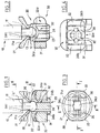
- an adjustment rod 10 intended to be moved in the direction of its axis for example to vary the orientation of a vehicle reflector.
- the rod 10 comprises a part 11 externally threaded, capable of cooperating for example with a tapping provided in a housing of the headlight, a generally spherical head 12 provided at the free end of the part 11, and an operating part (not shown) provided at the other end of the rod 10 to drive it in rotation for adjustment purposes.
- a mount 30, for example molded with a reflector on the rear face of the latter, allows the attachment to said reflector of an intermediate piece or capsule 20, preferably made by molding in one piece, having the essential function define for the head 12 a spherical cavity integral with the reflector.
- the mount 30 has for this purpose a body 31 in which is formed a housing 32 closed at a first lateral end and open at 32a at a second opposite lateral end.
- the housing 32 preferably extends laterally in a general direction essentially transverse to the axis of the rod 10 and has a well-defined height and width.
- the housing 32 is capable of receiving, with an extremely reduced clearance, as will be seen below, a body of the capsule 20.
- the body 24 of the capsule 20 has a width equal to or very slightly less than that of the housing 32. It defines a spherical cavity 24a for the head 12 of the rod 10 centrally.
- the body 24 further defines, in its region opposite to the cavity 24a (FIGS. 1 and 2), two essentially rigid lateral teeth 24b in the form of outward enlargements, intended to engage on the surface of the body 31 bordering the housing 32 and opposite the rod 10.
- the body 24 From the body 24, essentially at the level of its spherical cavity 24a, extend laterally two bent wings 22 intended to deform elastically during the positioning of the body 24 in the housing 32, in order to ensure a mounting of the type with recess, without play, of the frame 30 and of the capsule 20. More specifically, the rest position of the wings 22 is illustrated in FIG. 1 in dashed lines.
- the thickness of the body 31 is chosen so that, when the capsule and the mount are assembled, by sliding the body 24 in the housing 32 by the inlet 32a of the latter, the wings 22 are elastically separated from their position , upwards in FIG. 1, by the surface of the body 31 of the frame facing the rod 10.
- the wings 22 therefore exert permanently, at their edge 22a, a restoring force on said surface of the body 31 , to ensure firm immobilization of the frame and the capsule in the direction of the axis of the rod 10.
- transverse mounting of the capsule 20 on the mounting 30 can be advantageously used with any type of ball-joint mounting device, whether or not having the features described below.
- the capsule 20 comprises, around an opening 24c opening into the spherical cavity 24a, a part in the shape of a cone or corolla 21 ( Figures 1, 2 and 3).
- the purpose of this part 21 is to ensure, by its internal surface 21a, guiding the spherical head 12 as far as the alignment of the opening 24c during mounting of the reflector on a plurality (most often three) of spherical heads 12 by means of as many capsules 20.
- the spherical head 12 comprises, in the region of its transition with the intermediate part 11, a shoulder 13 of annular shape extending in a plane perpendicular to the axis of the rod 10.
- the distance between the ends of the tongues 26 and the shoulder 13 (at rest) is such that, when a pull, tending to cause the head 12 to come out of the cavity 24a, is exerted on the rod 10, the shoulder 13 comes into abutment against the regions tongues 26 terminals while the head 12 has not yet crossed the point of maximum resistance from which it is no longer retained by the walls of the cavity.
- the tongues 26 cannot deform elastically outwards (upwards in FIG. 1) since the arc of a circle described by their free end edges quickly cuts the edges of the intermediate part 11 ', which therefore hinders this movement.
- the tongues 26 therefore firmly limit the extraction stroke to a position of the rod and of the head such that the walls of the cavity 24a still exert a force bringing the head back into it and into its set position.
- a device is thus produced in which the tongues 26 make it possible to avoid inadvertent release of the head 12 without, in normal situation, they being in contact with the shoulder 13, and without them participating in the maintenance of the head.
- the rod 10 can see its inclination vary within certain limits, as illustrated in dashed lines in FIGS. 1 and 2, without the shoulder 13 being an obstacle thereto.
- the rod 11 carries in its region of transition with the head 12 a flange 14 of generally triangular section, the face 14a of which faces the rod is generally planar and perpendicular to the axis of the rod.
- the body 24 defining the spherical cavity 24a carries, in the vicinity of the opening of the cavity, two opposite tongues 126 directed generally towards one another and each carrying a triangular extension 126a directed towards the abovementioned surface 14a.
- the two tongues 126 define between them a free space wider than the diameter of the rod 11, in order to allow the angular deflections thereof.
- a circumferential groove 15 is provided in the head 12 and extends in a plane perpendicular to the axis of the rod 11. This groove is delimited, on the side of the free end of the head (on the right in the figure), by a flat annular surface.
- Two tongues 226 extend respectively in two diametrically opposite regions of the cavity 24a and each comprise a tooth 226a which has a straight stop surface and which projects into said cavity and engages in the groove 15.
- each tooth 226a At rest, the stop surface of each tooth 226a is spaced from the surface 15a of the groove, so that these teeth do not hinder the variations in inclination of the rod 11 carrying the head 12.
- the teeth 226a When traction is exerted on the rod 11, the teeth 226a come to oppose the movement of the surface 15a of the groove to limit the extraction movement to a position such that the walls of the cavity 24a, when the tensile stress has decreased or disappeared, return the head 12 to its set position in the cavity.
- the head 12 has at its free end a protruding stud 16 which defines a conical outer face and an inner face 16a generally flat and perpendicular to the axis of the rod 11.
- the bottom of the cavity 24a has a recess in which the stud 16 can penetrate when the blistering of the head 12 in its housing is produced.
- At least one flexible tongue 326 projects into the recess and has a terminal tooth 326a intended to cooperate by a stop edge with the surface 16a of the stud.
Landscapes
- Engineering & Computer Science (AREA)
- Mechanical Engineering (AREA)
- Non-Portable Lighting Devices Or Systems Thereof (AREA)
- Lighting Device Outwards From Vehicle And Optical Signal (AREA)
- Instrument Panels (AREA)
Claims (13)
- Montagevorrichtung zur Anbringung eines beweglichen Teils eines Kraftfahrzeugscheinwerfers an einem relativ feststehenden Teil, in der Ausführung mit einem allgemein kugelförmigen Kopf (12), der mit einem ersten der Teile durch eine Stange (11, 11') verbunden ist, und einer in etwa formschlüssigen Vertiefung (24a), die fest mit dem zweiten Teil verbunden ist, wobei der besagte Kopf in die Vertiefung durch eine in diese führende Öffnung (24c) eingedrückt wird, wobei wenigstens eine biegsame Zunge (26; 126; 226; 326) in der Nähe der besagten Vertiefung vorgesehen ist und sich elastisch verformen kann, um das Einsetzen des Kopfes darin zu ermöglichen und nach diesem Einsetzen einem Heraustreten des Kopfes aus der Vertiefung entgegenzuwirken, dadurch gekennzeichnet, daß die besagte Vertiefung (24a) alleine eine stabile Position für den Kopf (12) definiert, in der sich die besagte biegsame Zunge, die wenigstens vorgesehen ist, nicht mit dem besagten Kopf in Berührung befindet.
- Vorrichtung nach Anspruch 1 , dadurch gekennzeichnet, daß der Abstand zwischen der biegsamen Zunge (26; 126; 226; 326), die wenigstens vorgesehen ist, und dem Kopf (12) in der stabilen Position des besagten Kopfes so gewählt ist, daß, wenn sich der Kopf unter der Einwirkung einer Zugkraft verschiebt, um die besagte Zunge eingreifen zu lassen, die Wände der besagten Vertiefung noch eine Kraft ausüben, um den Kopf in seine stabile Position zurückzuführen.
- Vorrichtung nach Anspruch 1 oder 2 , dadurch gekennzeichnet, daß der besagte Kopf (12) eine allgemein ringförmige Schulter (13; 14a; 15a; 16a) aufweist, die mit der besagten Zunge (26; 126; 226; 326), die wenigstens vorgesehen ist, zusammenwirken kann, um dem Austreten entgegenzuwirken.
- Vorrichtung nach Anspruch 3 , dadurch gekennzeichnet, daß die besagte Schulter (3) in einem Übergangsbereich zwischen dem Kopf und der Stange vorgesehen ist.
- Vorrichtung nach Anspruch 4 , dadurch gekennzeichnet, daß die besagte Schulter (14a) an einem Kragen (14) vorgesehen ist, der von der besagten Stange (10) aus vorsteht.
- Vorrichtung nach Anspruch 3 , dadurch gekennzeichnet, daß die besagte Schulter (15a) in einer in den Kopf (12) eingearbeiteten Umfangsauskehlung (15) vorgesehen ist und daß die biegsame Zunge (226), die wenigstens vorgesehen ist, eine Verlängerung (226a) umfaßt, die in die besagte Auskehlung hineinragt, wenn der Kopf in die Vertiefung eingesetzt ist.
- Vorrichtung nach Anspruch 3 , dadurch gekennzeichnet, daß die besagte Schulter (16a) an einem Zapfen (16) vorgesehen ist, der auf der der Stange gegenüberliegenden Seite des Kopfes angeordnet ist, daß die Vertiefung an ihrem Boden eine Verstärkung aufweist, die für die Aufnahme des besagten Zapfens bestimmt ist, und daß die biegsame Zunge (326), die wenigstens vorgesehen ist, in die besagte Verstärkung hinreinragt und einen Zahn (326a) umfaßt, um mit der besagten Schulter zusammenzuwirken.
- Vorrichtung nach einem der Ansprüche 1 bis 7, dadurch gekennzeichnet, daß zwei diametral gegenüberliegende biegsame Zungen (26) vorgesehen sind.
- Vorrichtung nach einem der Ansprüche 1 bis 5, dadurch gekennzeichnet, daß die biegsame Zunge (26), die wenigstens vorgesehen ist, durch einen freistehenden Bereich eines konisch erweiterten Führungsteils (21) gebildet wird, der die besagte Öffnung (24c) der Vertiefung umgibt.
- Vorrichtung nach einem der Ansprüche 1 bis 9, dadurch gekennzeichnet, daß die besagte Vertiefung und die in diese mündende Öffnung durch ein Zwischenelement (20) gebildet werden, das an dem zweiten Teil angesetzt ist, daß das besagte Zwischenelement in eine an dem besagten Teil vorgesehene Aufnahme (32) in einer Richtung eingesetzt wird, die in etwa quer zur Richtung der Stange verläuft, und daß an dem besagten Zwischenelement wenigstens ein biegsamer Ansatz (22) vorgesehen ist, der eine spielfreie feste Verbindung zwischen dem besagten Zwischenelement und dem besagten Teil herbeiführt.
- Vorrichtung nach Anspruch 10, dadurch gekennzeichnet, daß zwei biegsame Ansätze (22) in einem ersten Bereich eines Körpers (24) des besagten Zwischenelements vorgesehen sind, der in die besagte Aufnahme (32) eingesetzt werden kann, wobei die besagten Ansätze jeweils durch beiderseits der besagten Aufnahme angeordnete erste Flächen des besagten zweiten Teils elastisch verformt werden können, und daß der besagte Körper in einem zweiten Bereich, der dem ersten im Verhältnis zur Aufnahme gegenüberliegt, zwei weitgehend starre Zähne (24b) aufweist, die jeweils mit zweiten Flächen zusammenwirken, die beiderseits der besagten Aufnahme angeordnet sind und den besagten jeweiligen ersten Flächen gegenüberliegen.
- Zwischenelement (20) für die Anbringung eines beweglichen Teils eines Kraftfahrzeugscheinwerfers an einem relativ feststehenden Teil, wobei ein allgemein kegelförmiger Kopf mit einem ersten der Teile durch eine Stange verbunden ist und eine in etwa formschlüssige Vertiefung fest an dem zweiten Teil angebracht ist, wobei der besagte Kopf in die Vertiefung durch eine in diese führende Öffnung eingedrückt wird, dadurch gekennzeichnet, daß es einen Körper (24) umfaßt, der die besagte Vertiefung (24a) enthält und in eine Aufnahme des besagten zweiten Teils eingesetzt werden kann, ferner wenigstens einen biegsamen Ansatz (22), der von dem Körper aus vorsteht und elastisch mit einer an die besagte Aufnahme angrenzenden Flächen zusammenwirken kann, um Spiele zwischen dem besagten Zwischenelement und dem besagten zweiten Teil zu verhindern, sowie wenigstens eine biegsame Zunge (26), die mit dem besagten Körper verbunden ist und sich in der Nähe der besagten Öffnung (24c) erstreckt, wobei sie sich in Richtung der Vertiefung elastisch verformen kann, um das Einsetzen des Kopfes darin zu ermöglichen und gleichzeitig einem Austreten des Kopfes aus der Vertiefung entgegenzuwirken.
- Zwischenelement nach Anspruch 12 , dadurch gekennzeichnet, daß sich der besagte biegsame Ansatz (22), der wenigstens vorgesehen ist, in einer Richtung erstreckt, die in etwa quer zur Einsetzrichtung des besagten Kopfes verläuft.
Applications Claiming Priority (2)
| Application Number | Priority Date | Filing Date | Title |
|---|---|---|---|
| FR9206364A FR2691415B1 (fr) | 1992-05-25 | 1992-05-25 | Dispositif de montage du genre rotule et element intermediaire, notamment pour reflecteur de projecteur de vehicule automobile. |
| FR9206364 | 1992-05-25 |
Publications (2)
| Publication Number | Publication Date |
|---|---|
| EP0572313A1 EP0572313A1 (de) | 1993-12-01 |
| EP0572313B1 true EP0572313B1 (de) | 1996-07-17 |
Family
ID=9430136
Family Applications (1)
| Application Number | Title | Priority Date | Filing Date |
|---|---|---|---|
| EP93401335A Expired - Lifetime EP0572313B1 (de) | 1992-05-25 | 1993-05-25 | Kugelbefestigung für Fahrzeugscheinwerferreflektor |
Country Status (6)
| Country | Link |
|---|---|
| US (1) | US5443323A (de) |
| EP (1) | EP0572313B1 (de) |
| JP (1) | JPH0636602A (de) |
| DE (1) | DE69303670T2 (de) |
| ES (1) | ES2092249T3 (de) |
| FR (1) | FR2691415B1 (de) |
Cited By (1)
| Publication number | Priority date | Publication date | Assignee | Title |
|---|---|---|---|---|
| DE102017123424A1 (de) | 2017-10-09 | 2019-04-11 | Böllhoff Verbindungstechnik GmbH | Winkelkupplung |
Families Citing this family (21)
| Publication number | Priority date | Publication date | Assignee | Title |
|---|---|---|---|---|
| FR2713729B1 (fr) * | 1993-12-07 | 1996-03-01 | Valeo Vision | Montage à rotule entre un miroir de projecteur de véhicule et une tige de réglage d'orientation. |
| FR2724349B1 (fr) * | 1994-09-08 | 1996-12-20 | Valeo Vision | Capsule pour le montage d'une tige de maintien sur l'arriere d'un miroir de projecteur de vehicule automobile, et projecteur comportant de telles capsules |
| ES2125776B1 (es) * | 1995-10-10 | 1999-12-16 | Fico Cables Sa | Cuerpo de rotula para terminales de cables de mando. |
| FR2757498B1 (fr) * | 1996-12-23 | 1999-02-26 | Decima | Dispositif de manutention d'une charge entre le sol et le sommet d'une structure porteuse |
| FR2759041B1 (fr) | 1997-02-05 | 1999-04-30 | Valeo Vision | Capsule pour le montage amorti d'un miroir dans un boitier de projecteur de vehicule automobile |
| FR2763304B1 (fr) * | 1997-05-14 | 1999-08-06 | Valeo Vision | Dispositif de pre-fixation d'un dispositif d'eclairage ou de signalisation sur une carrosserie de vehicule automobile |
| US20030197107A1 (en) * | 2000-04-13 | 2003-10-23 | Herbison Francis Dennis | Securement member |
| GB2364346B (en) * | 2000-07-05 | 2004-05-05 | Asg | Fastening arrangement |
| BR0006443A (pt) * | 2000-12-12 | 2004-06-08 | Dana Industrial Ltda | Articulação esférica com sistema de restrição de movimento angular |
| DE10156987A1 (de) * | 2001-11-21 | 2003-06-05 | Fico Cables Sa | Verbindungselement |
| JP2003175763A (ja) * | 2001-12-13 | 2003-06-24 | Koito Mfg Co Ltd | 車両用灯具 |
| DE102006018305B4 (de) * | 2006-04-20 | 2012-02-02 | Hella Kgaa Hueck & Co. | Scheinwerfer für Fahrzeuge |
| DE102009049237B4 (de) * | 2009-10-15 | 2018-09-13 | HELLA GmbH & Co. KGaA | Vorrichtung zur Befestigung eines Tragrahmens |
| KR101212942B1 (ko) * | 2009-11-30 | 2012-12-18 | 서울대학교산학협력단 | 자전거용 핸들 |
| US9140294B2 (en) | 2012-03-06 | 2015-09-22 | Burton Technologies, Llc | High extraction force ball socket |
| US9546679B2 (en) * | 2012-03-14 | 2017-01-17 | Kabushiki Kaisha Somic Ishikawa | Bearing seat for a ball joint and a ball joint |
| WO2017142973A1 (en) | 2016-02-16 | 2017-08-24 | Burton Technologies, Llc | Ball channel assembly |
| FR3061758B1 (fr) * | 2017-01-09 | 2024-02-16 | Mxs Group | Dispositif de fixation d'un accessoire a un mur par emboitage elastique |
| US11022171B2 (en) | 2018-06-20 | 2021-06-01 | Burton Technologies, Llc | Ball stud track assembly |
| CN111485391B (zh) * | 2019-01-25 | 2022-06-24 | 青岛海尔洗衣机有限公司 | 一种线屑过滤器的卡接装置、线屑过滤器及洗衣机 |
| US11125525B2 (en) * | 2019-03-12 | 2021-09-21 | KNS Precision, Inc. | Modular quick-change shooting platform feet |
Family Cites Families (12)
| Publication number | Priority date | Publication date | Assignee | Title |
|---|---|---|---|---|
| US3151897A (en) * | 1962-09-13 | 1964-10-06 | Adjustable Clamp Co | Swivel construction |
| FR2351350A1 (fr) * | 1976-05-14 | 1977-12-09 | Sev Marchal | Projecteur d'eclairage utilisable notamment sur des vehicules automobiles |
| GB1580182A (en) * | 1977-04-05 | 1980-11-26 | Fortune G W | Bearing housing for universal joints |
| DE3103954A1 (de) * | 1981-02-05 | 1982-09-02 | Lemförder Metallwaren AG, 2844 Lemförde | Kugelgelenk |
| US4765199A (en) * | 1987-01-27 | 1988-08-23 | Teleflex Incorporated | Quick connect cable coupler |
| FR2613440B1 (fr) * | 1987-04-01 | 1989-07-21 | Airax Sa | Articulation demontable a rotule |
| US4733625A (en) * | 1987-05-04 | 1988-03-29 | Allen William W | Quick release coupling device for anchor ropes |
| DE3728121A1 (de) * | 1987-08-22 | 1989-03-02 | Bosch Gmbh Robert | Kugelzapfenlagerung eines reflektors an rahmen von kraftfahrzeugscheinwerfern |
| DE8714461U1 (de) * | 1987-10-30 | 1989-03-02 | Robert Bosch Gmbh, 7000 Stuttgart | Scheinwerfer für Fahrzeuge, insbesondere Kraftfahrzeuge |
| DE8811059U1 (de) * | 1988-09-01 | 1989-12-28 | Robert Bosch Gmbh, 7000 Stuttgart | Kugelgelenk, insbesondere für Verstelleinrichtungen bei Scheinwerfern von Kraftfahrzeugen |
| JPH0787041B2 (ja) * | 1988-11-24 | 1995-09-20 | 株式会社小糸製作所 | 前照灯の組立方法 |
| US5153976A (en) * | 1992-03-23 | 1992-10-13 | Allied-Signal Inc. | Ball-and-socket assembly and method of making |
-
1992
- 1992-05-25 FR FR9206364A patent/FR2691415B1/fr not_active Expired - Fee Related
-
1993
- 1993-05-21 US US08/065,184 patent/US5443323A/en not_active Expired - Lifetime
- 1993-05-25 JP JP5122727A patent/JPH0636602A/ja active Pending
- 1993-05-25 DE DE69303670T patent/DE69303670T2/de not_active Expired - Lifetime
- 1993-05-25 EP EP93401335A patent/EP0572313B1/de not_active Expired - Lifetime
- 1993-05-25 ES ES93401335T patent/ES2092249T3/es not_active Expired - Lifetime
Cited By (3)
| Publication number | Priority date | Publication date | Assignee | Title |
|---|---|---|---|---|
| DE102017123424A1 (de) | 2017-10-09 | 2019-04-11 | Böllhoff Verbindungstechnik GmbH | Winkelkupplung |
| WO2019072556A1 (de) | 2017-10-09 | 2019-04-18 | Böllhoff Verbindungstechnik GmbH | Winkelkupplung |
| US12038033B2 (en) | 2017-10-09 | 2024-07-16 | Böllhoff Verbindungstechnik GmbH | Angle coupling |
Also Published As
| Publication number | Publication date |
|---|---|
| FR2691415B1 (fr) | 1998-06-12 |
| EP0572313A1 (de) | 1993-12-01 |
| DE69303670D1 (de) | 1996-08-22 |
| DE69303670T2 (de) | 1997-02-06 |
| US5443323A (en) | 1995-08-22 |
| FR2691415A1 (fr) | 1993-11-26 |
| ES2092249T3 (es) | 1996-11-16 |
| JPH0636602A (ja) | 1994-02-10 |
Similar Documents
| Publication | Publication Date | Title |
|---|---|---|
| EP0572313B1 (de) | Kugelbefestigung für Fahrzeugscheinwerferreflektor | |
| EP1213980B1 (de) | Vorrichtung zur positionsverriegelung eines bezüglich eines ortsfesten elements beweglichen teils | |
| EP0688695B1 (de) | Verriegelung eines beweglichen Bauteiles in einem Kraftfahrzeugsitz | |
| EP0053543B1 (de) | Anordnungen zum Befestigen von Gegenständen an Blechen, welche nur von einer Seite her zugänglich sind | |
| EP1850017A2 (de) | Selbstsperrende Verbindung zwischen einem Flachteil und einer Stange mit kugelförmigem Ende | |
| EP0402198B1 (de) | Verriegelungsmutter | |
| FR2703477A1 (fr) | Charnière, notamment pour monture de lunettes. | |
| FR2894304A1 (fr) | Dispositif d'assemblage de deux plaques | |
| EP0196966B1 (de) | Kupplungsausrücker, insbesondere für ein Kraftfahrzeug | |
| EP0050079B1 (de) | Mit einer Verzahnung versehene Gelenkvorrichtung zur Sicherheitsentriegelung | |
| FR3012543A1 (fr) | Ensemble de liaison par anneau d'arret pour troncon d'arbre | |
| EP1423642B1 (de) | Lichteinheit für fahrzeugscheinwerfer | |
| EP0443895A1 (de) | Vorrichtung zum Kuppeln von zwei koaxialen Rohren | |
| EP3796481B1 (de) | Steckverbinder mit spielausgleich, verbindungsvorrichtung und anordnung mit einer solchen vorrichtung | |
| EP0549383B1 (de) | Käfig für Drehgelenk | |
| WO1994028329A1 (fr) | Frein a disque a etrier coulissant | |
| FR2654705A1 (fr) | Bouchon de reservoir, en particulier bouchon de reservoir a carburant pour vehicule automobile. | |
| EP0369853B1 (de) | Kupplungsvorrichtung zwischen Fenster und Fensterheber mit schwingenden Armen in einem Kraftfahrzeug | |
| EP1160128B1 (de) | Beleuchtungsvorrichtung oder Anzeigevorrichtung für Kraftfahrzeug mit zwei Teilen durch Schnappverschluss verbunden | |
| EP0565422B1 (de) | Montageeinrichtung für ein Teil eines Kraftfahrzeugscheinwerfers | |
| EP0578563B1 (de) | Scheibenwischerblatt | |
| EP1179469B1 (de) | Lenksäule für ein Kraftfahrzeuglenksystem | |
| FR2713729A1 (fr) | Montage à rotule entre un miroir de projecteur de véhicule et une tige de réglage d'orientation. | |
| EP0745804B1 (de) | Kfz-Scheinwerfer mit einem verbesserten Lampenträger für Standlicht | |
| EP0524105B1 (de) | Nichtabmontierbares Zwischenstück, insbesondere zum Einstellen der Orientierung von Fahrzeugscheinwerfern |
Legal Events
| Date | Code | Title | Description |
|---|---|---|---|
| PUAI | Public reference made under article 153(3) epc to a published international application that has entered the european phase |
Free format text: ORIGINAL CODE: 0009012 |
|
| AK | Designated contracting states |
Kind code of ref document: A1 Designated state(s): DE ES FR GB IT |
|
| 17P | Request for examination filed |
Effective date: 19940405 |
|
| 17Q | First examination report despatched |
Effective date: 19950915 |
|
| GRAH | Despatch of communication of intention to grant a patent |
Free format text: ORIGINAL CODE: EPIDOS IGRA |
|
| GRAH | Despatch of communication of intention to grant a patent |
Free format text: ORIGINAL CODE: EPIDOS IGRA |
|
| GRAA | (expected) grant |
Free format text: ORIGINAL CODE: 0009210 |
|
| AK | Designated contracting states |
Kind code of ref document: B1 Designated state(s): DE ES FR GB IT |
|
| REF | Corresponds to: |
Ref document number: 69303670 Country of ref document: DE Date of ref document: 19960822 |
|
| ITF | It: translation for a ep patent filed | ||
| GBT | Gb: translation of ep patent filed (gb section 77(6)(a)/1977) |
Effective date: 19960930 |
|
| REG | Reference to a national code |
Ref country code: ES Ref legal event code: FG2A Ref document number: 2092249 Country of ref document: ES Kind code of ref document: T3 |
|
| PLBE | No opposition filed within time limit |
Free format text: ORIGINAL CODE: 0009261 |
|
| STAA | Information on the status of an ep patent application or granted ep patent |
Free format text: STATUS: NO OPPOSITION FILED WITHIN TIME LIMIT |
|
| 26N | No opposition filed | ||
| REG | Reference to a national code |
Ref country code: GB Ref legal event code: IF02 |
|
| PGFP | Annual fee paid to national office [announced via postgrant information from national office to epo] |
Ref country code: GB Payment date: 20070511 Year of fee payment: 15 |
|
| GBPC | Gb: european patent ceased through non-payment of renewal fee |
Effective date: 20080525 |
|
| PG25 | Lapsed in a contracting state [announced via postgrant information from national office to epo] |
Ref country code: GB Free format text: LAPSE BECAUSE OF NON-PAYMENT OF DUE FEES Effective date: 20080525 |
|
| PGFP | Annual fee paid to national office [announced via postgrant information from national office to epo] |
Ref country code: ES Payment date: 20110525 Year of fee payment: 19 |
|
| PGFP | Annual fee paid to national office [announced via postgrant information from national office to epo] |
Ref country code: IT Payment date: 20110530 Year of fee payment: 19 |
|
| PGFP | Annual fee paid to national office [announced via postgrant information from national office to epo] |
Ref country code: DE Payment date: 20120514 Year of fee payment: 20 |
|
| PGFP | Annual fee paid to national office [announced via postgrant information from national office to epo] |
Ref country code: FR Payment date: 20120615 Year of fee payment: 20 |
|
| PG25 | Lapsed in a contracting state [announced via postgrant information from national office to epo] |
Ref country code: IT Free format text: LAPSE BECAUSE OF NON-PAYMENT OF DUE FEES Effective date: 20120525 |
|
| REG | Reference to a national code |
Ref country code: DE Ref legal event code: R071 Ref document number: 69303670 Country of ref document: DE |
|
| PG25 | Lapsed in a contracting state [announced via postgrant information from national office to epo] |
Ref country code: DE Free format text: LAPSE BECAUSE OF EXPIRATION OF PROTECTION Effective date: 20130528 |
|
| REG | Reference to a national code |
Ref country code: ES Ref legal event code: FD2A Effective date: 20130820 |
|
| PG25 | Lapsed in a contracting state [announced via postgrant information from national office to epo] |
Ref country code: ES Free format text: LAPSE BECAUSE OF NON-PAYMENT OF DUE FEES Effective date: 20120526 |