EP0571307B1 - Tronçons de chemin de câbles auto-encastrables et procédé de fabrication de tels troncons - Google Patents
Tronçons de chemin de câbles auto-encastrables et procédé de fabrication de tels troncons Download PDFInfo
- Publication number
- EP0571307B1 EP0571307B1 EP93460020A EP93460020A EP0571307B1 EP 0571307 B1 EP0571307 B1 EP 0571307B1 EP 93460020 A EP93460020 A EP 93460020A EP 93460020 A EP93460020 A EP 93460020A EP 0571307 B1 EP0571307 B1 EP 0571307B1
- Authority
- EP
- European Patent Office
- Prior art keywords
- cable duct
- section
- duct section
- channel
- coupling element
- Prior art date
- Legal status (The legal status is an assumption and is not a legal conclusion. Google has not performed a legal analysis and makes no representation as to the accuracy of the status listed.)
- Expired - Lifetime
Links
- 238000004519 manufacturing process Methods 0.000 title claims description 7
- 238000000034 method Methods 0.000 title claims description 6
- 238000001338 self-assembly Methods 0.000 title 1
- 230000008878 coupling Effects 0.000 claims abstract description 57
- 238000010168 coupling process Methods 0.000 claims abstract description 57
- 238000005859 coupling reaction Methods 0.000 claims abstract description 57
- 230000000295 complement effect Effects 0.000 claims abstract description 6
- 238000003466 welding Methods 0.000 claims description 19
- 239000002184 metal Substances 0.000 claims description 13
- 229910052751 metal Inorganic materials 0.000 claims description 13
- 230000002441 reversible effect Effects 0.000 claims description 10
- 238000005452 bending Methods 0.000 claims description 7
- 239000000463 material Substances 0.000 claims description 5
- 238000005520 cutting process Methods 0.000 claims description 4
- 238000003825 pressing Methods 0.000 claims 1
- 238000005260 corrosion Methods 0.000 description 4
- 238000000576 coating method Methods 0.000 description 2
- 239000002131 composite material Substances 0.000 description 2
- 230000007797 corrosion Effects 0.000 description 2
- 238000005246 galvanizing Methods 0.000 description 2
- 238000009434 installation Methods 0.000 description 2
- 229920000728 polyester Polymers 0.000 description 2
- 229910001220 stainless steel Inorganic materials 0.000 description 2
- 239000010935 stainless steel Substances 0.000 description 2
- 241000269420 Bufonidae Species 0.000 description 1
- 229910000831 Steel Inorganic materials 0.000 description 1
- 208000027418 Wounds and injury Diseases 0.000 description 1
- HCHKCACWOHOZIP-UHFFFAOYSA-N Zinc Chemical compound [Zn] HCHKCACWOHOZIP-UHFFFAOYSA-N 0.000 description 1
- 239000011248 coating agent Substances 0.000 description 1
- 239000000470 constituent Substances 0.000 description 1
- 230000006378 damage Effects 0.000 description 1
- 230000006866 deterioration Effects 0.000 description 1
- 238000006073 displacement reaction Methods 0.000 description 1
- 239000000835 fiber Substances 0.000 description 1
- 239000011152 fibreglass Substances 0.000 description 1
- 208000014674 injury Diseases 0.000 description 1
- 238000003754 machining Methods 0.000 description 1
- 239000013307 optical fiber Substances 0.000 description 1
- 239000003973 paint Substances 0.000 description 1
- 238000007747 plating Methods 0.000 description 1
- 230000001681 protective effect Effects 0.000 description 1
- 238000003892 spreading Methods 0.000 description 1
- 239000010959 steel Substances 0.000 description 1
- 238000003860 storage Methods 0.000 description 1
- 239000000126 substance Substances 0.000 description 1
- 238000004381 surface treatment Methods 0.000 description 1
- 239000011701 zinc Substances 0.000 description 1
- 229910052725 zinc Inorganic materials 0.000 description 1
Images


Classifications
-
- H—ELECTRICITY
- H02—GENERATION; CONVERSION OR DISTRIBUTION OF ELECTRIC POWER
- H02G—INSTALLATION OF ELECTRIC CABLES OR LINES, OR OF COMBINED OPTICAL AND ELECTRIC CABLES OR LINES
- H02G3/00—Installations of electric cables or lines or protective tubing therefor in or on buildings, equivalent structures or vehicles
- H02G3/02—Details
- H02G3/06—Joints for connecting lengths of protective tubing or channels, to each other or to casings, e.g. to distribution boxes; Ensuring electrical continuity in the joint
- H02G3/0608—Joints for connecting non cylindrical conduits, e.g. channels
-
- H—ELECTRICITY
- H02—GENERATION; CONVERSION OR DISTRIBUTION OF ELECTRIC POWER
- H02G—INSTALLATION OF ELECTRIC CABLES OR LINES, OR OF COMBINED OPTICAL AND ELECTRIC CABLES OR LINES
- H02G3/00—Installations of electric cables or lines or protective tubing therefor in or on buildings, equivalent structures or vehicles
- H02G3/02—Details
- H02G3/04—Protective tubing or conduits, e.g. cable ladders or cable troughs
- H02G3/0437—Channels
- H02G3/0443—Channels formed by wire or analogous netting
Definitions
- the present invention relates to the production of gutter-shaped structures for supporting and guiding cables such as, for example, electric cables, telephone cables, fiber optic cables, computer network cables or any similar flexible conduits.
- These structures are designated by the term of cable trays and are produced by the assembly of different sections having a variable length and width depending on the number of cables to be laid inside the gutter they form and of the length of the path to travel.
- the sections constituting these cable trays are conventionally made up of perforated sheet metal structures in order to lighten them or by lattices of mechanically welded steel wires. In order to resist corrosion, these metal structures generally undergo a surface treatment of conventional invoice such as a coating of paint, zinc plating or hot galvanization. The use of stainless steel is sometimes necessary to combat the most aggressive atmospheres.
- These sections can also be made of composite materials such as reinforced polyester.
- the sections of cable tray made from wires, chains and wefts organized in lattices are generally formed by flat welding of the wires together. This welding is carried out in gauges having a variable dimensioning as a function of the size of the section which it is desired to obtain. Once this welding operation has been carried out, the mesh is deformed by bending or by bending, so as to take the form of a gutter.
- a complete cable tray is produced by assembling a determined number of these sections, as a function of the length of the path to be covered by the cables.
- the main problem posed by the assembly of the cable tray sections of the prior art consists of the different operations and the different systems used to make the junction between the different sections.
- One of the oldest methods used to assemble the sections of cable tray therebetween consists in using inserts being presented under the form of splices and to bolt them between two sections of consecutive cable trays.
- the fixing of the fishplates by means of bolts requires that these be perforated so as to be able to introduce a screw therein, the latter then being blocked by a nut between two end weft threads by means of a jumper.
- This old solution has various drawbacks, including the high cost of labor and material.
- patent document No. FR 2208219 which relates to a device for assembling sections of cable trays constituted by lattices of welded wires, characterized in that it laterally comprises at least two rigid ribs in their central part. and elastic in their end part, said ribs being placed between two longitudinal elements of two sections of cable tray and being held in place by virtue of their ends which each engage on a transverse wire of each of the two sections of path of cable.
- This device has the major drawback of requiring a special tool for the installation of the elastic ribs in question.
- This tool which has the ability to tension and pull at the same time the elastic ends of the splint so that it comes to hang on certain wires of the mesh of the trellis constituting the section of cable tray, requires significant clearance for to be manipulated.
- the cable trays are often arranged along the walls in a position which does not allow such a clearance.
- Another drawback presented by the device for assembling cable tray sections according to this French patent document consists in the fact that once the ribs are placed between the sections, it is very difficult to remove them.
- the disclosed device promotes the assembly of cable tray sections, it disadvantages their disassembly and thus their reuse.
- the fishplates used involve several sharp angles which contribute to increasing the risk of injury inside the gutter with respect to the cables arranged therein and outside the gutter with respect to workers mounting these cable trays or walls located nearby.
- the assembly device described in this patent is not suitable for use with the sections of cable trays formed by perforated sheets.
- assembly devices which consist of plates matching the edges of the gutters forming the cable tray and having perforations capable of coming into contact with the perforations of the sections.
- These parts can be arranged at the junction between the sections and secured to them by means of clips or screws making it possible to firmly press the assembly parts against the sections.
- these screws have the drawback of requiring special tools to be put in place and the clips have the drawback of being difficult to separate sections once they have been placed. on these.
- the clips or screws described extend well outside the sections, which significantly increases their size and are potential sources of pullout vis-à-vis the various structures located near the cable trays .
- the objective of the present invention is to provide a section of cable tray which can be connected to another identical section without the intervention of an insert.
- Another objective of the invention is to provide such a section which does not have the drawbacks of prior art devices for assembling sections of cable trays.
- the invention aims to provide such a section for mounting a cable tray with a substantial time saving.
- Another object of the invention is also to facilitate the disassembly of such cable trays.
- Another objective of the invention is to provide a section of cable tray, the assembly of which makes it possible to remove any bolt or accessory as well as any standard or special tool necessary for mounting such bolts or accessories.
- Another complementary objective of the invention is also to provide a section of cable tray having a harmonious aesthetic appearance.
- Another objective of the invention is to propose a section of cable tray having characteristics facilitating the mounting thereon of covers.
- a section of cable tray which is in the form of a gutter, characterized in that it is constituted by an asymmetrical module having two complementary ends each forming a reversible embedding coupling member, a first coupling member consisting of at least one fishplate whose proximal end is welded to said gutter and whose distal end is provided with a coupling lug, the second coupling member being formed in at least part of said gutter and being capable of receiving said coupling pin.
- said section comprises at least two fishplates whose proximal ends are welded to the side walls of said gutter, symmetrically with respect to the longitudinal axis of the latter, so as to face each other.
- said section comprises at least two fishplates, one of said fishplates being welded to the end of one of the side walls of said gutter and the other fishplate being welded to the opposite end of the other wall lateral of said gutter.
- the first variant consisting in welding the ribs on the side walls of the gutter so as to face each other is the preferred solution because it makes it easier to store and assemble the sections of cable trays.
- said coupling lug is constituted by a finger projecting from the surface of said splint and formed by cutting or stamping therein, the material constituting said splice having sufficient elasticity to allow the lug to snap onto the second coupling member, during the assembly operation with another section of cable tray.
- the lug of each splint can snap onto the second coupling member of another section of cable tray and thus achieve a secure connection between the sections, but can also escape this second coupling member which retains it and thereby facilitates the uncoupling of the two cable tray sections thus connected.
- the reversibility of the assembly of the sections according to the invention is made possible, within the framework of this preferential aspect of the invention, thanks to the cutting of the lug in the very distal ends of the fishplates.
- the material constituting the ribs has sufficient elasticity to allow the lugs to be returned to the rest position, when they are separated from the second coupling member.
- said section of cable tray consists of a lattice of metal wires welded together, said second coupling member being constituted by at least one mesh of said lattice.
- the width of said mesh forming said second coupling member is very slightly greater than that of said fishplate constituting said first coupling member, so as to allow low clearance guiding of said splice in said mesh.
- the length of said mesh forming said second coupling member is of a length such that the connection between the first coupling member constituted by a fishplate of said section and the second coupling member constituted by a mesh another section is a hyperstatic connection in the installation position.
- said section is constituted by a perforated sheet, said second coupling member being constituted by at least one perforation of said sheet.
- said fishplates have no roughness protruding outside of said section in order to accommodate a cover.
- the covers used can be of different types and will advantageously have an aesthetic appearance harmonious with the appearance of the sections themselves. They may for example be made of full sheet metal and snap onto the upper part of the sections and will preferably have the same length as these.
- the section of cable tray comprises at least one splice welded by its proximal end to the central part of said section forming the bottom of said gutter.
- one or more central fishplates secure the assembly of the sections between them.
- the welding operation of said one or more fishplates is carried out by electric spot welding.
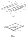
- a section 1a intended to form a constituent element of a cable tray which can be of various nature (telephone cables, electric cables, computer network cables, optical fiber cables and various flexible conduits, etc.) is shown in perspective.
- This section consists of a lattice 2 of mechanically welded son together in a perpendicular pattern delimiting mesh of son.
- the section la is in the form of a gutter having a bottom 14 and side walls 15, 16.
- the trellis 2 has undergone an electro-galvanizing treatment, in order to avoid the problems due to electro-corrosion. chemical of the metal. It should be noted that other types of treatment against corrosion can be used such as hot-dip galvanizing after machining or the use of polymerized coatings.
- the use of stainless steel is made compulsory by the aggressiveness of the surrounding atmosphere.
- lattices of son of composite materials polyyester reinforced with fiberglass or the like .
- the anti-corrosion treatment of the wires can take place before the welding of these wires to each other to form the trellis.
- the section of cable tray has a height of 60 mm and a width of 150 mm.
- this type of trellis may have a different width and / or height depending on the use that it is desired to make of the cable tray formed by the assembly of such sections.
- the section of the cable tray is in the form of an asymmetrical module having two complementary ends each forming a coupling member in a reversible position.
- a first coupling member is constituted by two metal splices 3.
- Each of these ribs 3 has a width very slightly less than the width of the meshes 8 of the trellis 2 which receives them.
- Each of the fishplates 3 is positioned in one of these meshes 8 so as not to protrude outside the side walls 15, 16 of the gutter.
- the proximal ends 4 of the fishplates 3 are each secured to the meshes 8 by two welding points 13. These welding points 13 make it possible to securely fasten the fishplates 3 to the wire mesh 2.
- the second coupling member is constituted by the two meshes 7 situated at the end of the section opposite to that at the level of which the meshes 8 are located.
- the method of manufacturing such a section consists of welding flat the fishplates 3 and the wires constituting the mesh network of the trellis 2, then forming the gutter by bending or by folding this trellis provided with the fishplates 3.
- these fixing devices comprise, as shown in FIG. 2, welded plates 10 to one of the meshes 11 constituting the bottom of the gutter formed by the sections and are provided with openings 9.
- the welding of such devices makes it possible to reduce the number of accessories (such as jumpers, plates, toads) that must be used to secure the cable trays to a support.
- the distal end 5 of a fishplate 3 is shown in perspective.
- This distal end 5 is provided with a coupling lug 6 capable of cooperating with a wire 12 of a mesh 7 of another section of cable tray.
- Said coupling lug 6 is formed by cutting in said splint 3 a finger projecting from the contact surface of the splint 3, and capable of spreading to avoid the wire 12 during the operation assembly by embedding with another section of cable tray.
- the ribs 3 of a section constituting the first coupling member are introduced into the meshes 7 constituting the second coupling member of another section.
- the deformation of the splint 3 is such that it allows the reversibility of the positioning of the lug 6 on the wire 12.
- This lug 6 is directed towards the inside of the gutter formed by the lattice 2.
- the other splint 3 has a structure similar to that shown in FIG. 3 except that the lug 6 is formed so as to also be directed towards the interior of the trough of the trellis 2.
- connection by embedding of two sections 1a, 1b of cable tray according to the invention is achieved by introducing the coupling members constituted by fishplates 3 of a first section 1a in the coupling members formed by the meshes 7 of a second section 1b, in the direction displayed by the arrow.
- the sections 1a and 1b are shown partially, the section 1b not being provided with its first coupling member and the section 1a not being provided with its second coupling member.
- an annex connection device between two sections of cable tray according to the invention is in the form of a clip 17 which can be installed so as to connect the metallic wires of two meshes belonging to the central part of two successive sections.
- the clip 17 has two elastic branches 18, 19.
- this clip 17 will be welded to the trellis at the end comprising the ribs 3.
- connection by embedding of a section 1a to another section 1b is carried out according to a simple and rapid operation requiring no conventional or specific tool.
- the assembly is carried out without the use of any bolts or other accessories and has excellent mechanical resistance.
- This assembly can be carried out in conditions of minimum bulk, for example when the cable tray must be formed along a wall.
- the cable tray made by assembling different sections has a harmonious aesthetic appearance, since the connection fishplates fit perfectly into the whole.
- the design of the fishplates 3 makes it possible to easily separate the various sections constituting a cable tray by performing reverse traction in the direction represented by the arrow.
- the fishplates having no external or internal roughness, the risk of cable tearing or deterioration of the materials located near the cable trays is very reduced. This makes it easier to fit a cover on the cable tray.
- a cable tray made in accordance with Figure 4 is shown partially.
- This cable tray includes the two sections 1a and 1b shown in part and interconnected by means of the fishplates 3 of the section 1a.
- This cable tray has no external roughness, since the lugs 6 of the fishplates 3 are directed towards the inside of the gutter formed by the cable tray. It can therefore easily accommodate a cover 20 consisting of a metal plate whose profile allows it to be fitted on the sections 1a and 1b. For the purposes of the description, this cover 20 is shown in part.
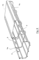
- two sections 21a, 21b are shown in perspective on the point of being connected by reversible embedding.
- These cable tray sections consist of perforated sheets.
- the sections 21a and 21b are shown partially, the section 21b not being provided with its first coupling member.
- the first coupling member of the section 21a is constituted by two ribs 23 formed in a perforated sheet, and whose proximal ends 24 are welded to the side walls 35, 36 of the part forming the gutter of the section 21a.
- the distal ends 25 of these ribs 23 are, for their part, provided with coupling pins 26 formed by stamping in the perforated sheet forming the ribs 23.
- Said coupling pins 6 come, in the rest position, projecting from relative to the contact surface of the ribs 23. Their slope allows the slight lateral displacement of the ribs during the assembly operation with the section of cable tray 21B. The lateral play of the splint inside the rolled edge is made possible by the difference between the thickness of the splint and the internal width of the rolled edge.
- the ribs 23 of a section of cables constituting the first coupling member are embedded in the perforations 27 of another section constituting the second coupling member.
- the possible deformation of the ribs 23 is such that it allows the reversibility of the positioning of the pins 26 in the perforations 27.
Landscapes
- Engineering & Computer Science (AREA)
- Architecture (AREA)
- Civil Engineering (AREA)
- Structural Engineering (AREA)
- Details Of Indoor Wiring (AREA)
- Packaging Of Annular Or Rod-Shaped Articles, Wearing Apparel, Cassettes, Or The Like (AREA)
- Installation Of Indoor Wiring (AREA)
- Near-Field Transmission Systems (AREA)
- Insulated Conductors (AREA)
Applications Claiming Priority (2)
| Application Number | Priority Date | Filing Date | Title |
|---|---|---|---|
| FR9206461 | 1992-05-22 | ||
| FR929206461A FR2691590B1 (fr) | 1992-05-22 | 1992-05-22 | Troncons de chemin de cables auto-encastrables et procede de fabrication de tels troncons. |
Publications (2)
| Publication Number | Publication Date |
|---|---|
| EP0571307A1 EP0571307A1 (fr) | 1993-11-24 |
| EP0571307B1 true EP0571307B1 (fr) | 1996-09-04 |
Family
ID=9430219
Family Applications (1)
| Application Number | Title | Priority Date | Filing Date |
|---|---|---|---|
| EP93460020A Expired - Lifetime EP0571307B1 (fr) | 1992-05-22 | 1993-05-21 | Tronçons de chemin de câbles auto-encastrables et procédé de fabrication de tels troncons |
Country Status (7)
| Country | Link |
|---|---|
| EP (1) | EP0571307B1 (enExample) |
| AT (1) | ATE142381T1 (enExample) |
| DE (1) | DE69304416T2 (enExample) |
| DK (1) | DK0571307T3 (enExample) |
| ES (1) | ES2093949T3 (enExample) |
| FR (1) | FR2691590B1 (enExample) |
| GR (1) | GR3021826T3 (enExample) |
Families Citing this family (34)
| Publication number | Priority date | Publication date | Assignee | Title |
|---|---|---|---|---|
| FR2728649A1 (fr) * | 1994-12-22 | 1996-06-28 | Metal Deploye Sa | Chemin de cables en fils |
| US6019323A (en) * | 1996-04-25 | 2000-02-01 | Jette; Roger | Flexible cable management system |
| US6361000B1 (en) | 1996-04-25 | 2002-03-26 | Roger Jette | Flexible cable management system |
| FR2751723B1 (fr) * | 1996-07-26 | 1998-09-11 | Metal Deploye Sa | Eclisse d'assemblage pour troncons de chemins de cables et troncons de chemins de cables obtenus |
| ES2156487B1 (es) * | 1997-07-02 | 2003-04-01 | Basor Electric S A | Empalme para bandejas portacables. |
| DE19815047B4 (de) * | 1997-09-24 | 2006-08-17 | Obo Bettermann Gmbh & Co. Kg | Anordnung zur schraubenlosen Verbindung von Gitterkabelbahnen |
| DE19831145C1 (de) * | 1998-07-11 | 1999-11-11 | Bettermann Obo Gmbh & Co Kg | Gitterkabelrinne |
| DE19946388B4 (de) * | 1998-07-11 | 2007-08-16 | Obo Bettermann Gmbh & Co. Kg | Gitterkabelrinne |
| DE19841643B4 (de) * | 1998-09-11 | 2007-04-12 | Obo Bettermann Gmbh & Co. Kg | Kabelrinne aus Blech |
| US6637704B2 (en) | 1999-06-24 | 2003-10-28 | Roger Jette | Flexible cable support apparatus and method |
| US6460812B1 (en) | 1999-06-24 | 2002-10-08 | Roger Jette | Flexible cable support apparatus and method |
| FR2814602B1 (fr) * | 2000-09-27 | 2003-10-24 | Tolmega | Troncon de chemin a cables a eclisse retractable, chemins a cables obtenus par assemblage de tels troncons |
| FR2825528B1 (fr) * | 2001-06-01 | 2003-08-29 | Bernard Hennequin | Systeme d'assemblage pour elements de chemin de cables en treillis de fils metalliques |
| US6709186B2 (en) | 2001-11-16 | 2004-03-23 | Adc Telecommunications, Inc. | Coupler for cable trough |
| US6926236B2 (en) | 2002-03-04 | 2005-08-09 | Roger Jette | Cable tray apparatus and method |
| MXPA04009279A (es) | 2002-03-27 | 2005-01-25 | Adc Telecommunications Inc | Acoplador de canalizacion para cables. |
| US7093997B2 (en) | 2002-03-27 | 2006-08-22 | Adc Telecommunications, Inc. | Coupler for cable trough |
| US20050175519A1 (en) | 2004-02-06 | 2005-08-11 | Rogers William A.Jr. | Microchannel compression reactor |
| GB2399459B (en) * | 2004-03-22 | 2005-02-16 | Legrand Electric Ltd | Cable trunking and ducting |
| DE202004019942U1 (de) | 2004-12-24 | 2006-04-27 | Obo Bettermann Gmbh & Co. Kg | Kabeltragvorrichtung |
| US7315680B1 (en) | 2006-06-21 | 2008-01-01 | Adc Telecommunications, Inc. | Cable routing devices with integrated couplers |
| US7815152B2 (en) | 2007-02-21 | 2010-10-19 | Adc Telecommunications, Inc. | Coupler for cable trough |
| US7481597B2 (en) | 2007-02-21 | 2009-01-27 | Adc Telecommunications, Inc. | Coupler for cable trough |
| US7463809B2 (en) | 2007-02-21 | 2008-12-09 | Adc Telecommunications, Inc. | Coupler for cable trough |
| US7896295B2 (en) | 2007-02-21 | 2011-03-01 | Adc Telecommunications, Inc. | Coupler for cable trough |
| US7493005B2 (en) | 2007-02-21 | 2009-02-17 | Adc Telecommunications, Inc. | Coupler for cable trough |
| US7584929B2 (en) | 2007-02-21 | 2009-09-08 | Adc Telecommunications, Inc. | Coupler for cable trough |
| US7504583B2 (en) | 2007-02-21 | 2009-03-17 | Adc Telecommunications, Inc. | Coupler for cable trough |
| ES1069695Y (es) * | 2009-01-30 | 2009-08-10 | Pemsa Pequeno Material Electri | Accesorio mejorado para empalme de bandejas y/o canales portacables |
| TR201105767A2 (tr) * | 2011-06-13 | 2012-12-21 | Kiraç Metal Ürünleri̇ San. Ve Ti̇c. Ltd. Şti̇. | Hiçbir bağlantı aracına ihtiyaç duymayan kolay geçmeli kablo taşıma kanalı. |
| ES2396209B1 (es) * | 2011-07-14 | 2014-01-30 | Valdinox, S.L. | Tramo de bandeja portacables. |
| FR3007592B1 (fr) | 2013-06-20 | 2015-07-17 | Cts Cable Tray Systems Sas | Troncon de chemin de cables a encliquetage transversal, chemin de cables comprenant de tels troncons et procede de fabrication |
| ES2695452A1 (es) * | 2017-06-29 | 2019-01-04 | Unex Aparellaje Electrico Sl | Procedimiento de fabricación de una bandeja portacables de rejilla, y bandeja portacables de rejilla correspondiente |
| ES1201060Y (es) | 2017-11-06 | 2018-09-19 | Pemsa Cable Man S A | Dispositivo de union para bandejas portacables de rejilla y tramo de bandeja portacables de rejilla |
Family Cites Families (3)
| Publication number | Priority date | Publication date | Assignee | Title |
|---|---|---|---|---|
| US3042351A (en) * | 1960-05-27 | 1962-07-03 | Bois Marvin A Du | Cable trays |
| US3161722A (en) * | 1963-02-13 | 1964-12-15 | Otis Elevator Co | Ready access wiring duct |
| FR2208219B1 (enExample) | 1972-11-27 | 1976-04-23 | Metal Deploye Sa |
-
1992
- 1992-05-22 FR FR929206461A patent/FR2691590B1/fr not_active Expired - Fee Related
-
1993
- 1993-05-21 EP EP93460020A patent/EP0571307B1/fr not_active Expired - Lifetime
- 1993-05-21 DK DK93460020.6T patent/DK0571307T3/da active
- 1993-05-21 AT AT93460020T patent/ATE142381T1/de active
- 1993-05-21 ES ES93460020T patent/ES2093949T3/es not_active Expired - Lifetime
- 1993-05-21 DE DE69304416T patent/DE69304416T2/de not_active Expired - Lifetime
-
1996
- 1996-11-28 GR GR960403217T patent/GR3021826T3/el unknown
Also Published As
| Publication number | Publication date |
|---|---|
| DK0571307T3 (enExample) | 1997-02-24 |
| FR2691590B1 (fr) | 1994-07-29 |
| ES2093949T3 (es) | 1997-01-01 |
| EP0571307A1 (fr) | 1993-11-24 |
| FR2691590A1 (fr) | 1993-11-26 |
| GR3021826T3 (en) | 1997-02-28 |
| DE69304416D1 (de) | 1996-10-10 |
| ATE142381T1 (de) | 1996-09-15 |
| DE69304416T2 (de) | 1997-04-03 |
Similar Documents
| Publication | Publication Date | Title |
|---|---|---|
| EP0571307B1 (fr) | Tronçons de chemin de câbles auto-encastrables et procédé de fabrication de tels troncons | |
| CA2181938C (fr) | Element porteur pour structures en treillis | |
| WO1998027630A1 (fr) | Console pour conduits porteurs | |
| FR2796121A1 (fr) | Accessoire de fixation pour chemin de cables en fils, et chemin de cables en fils equipe au moins d'un tel accessoire | |
| WO2009013399A1 (fr) | Dispositif de cheminement de cables | |
| FR2697690A1 (fr) | Ensemble de support et de chemin de câbles. | |
| EP2221518A2 (fr) | Pièce de fixation d'un tronçon de chemin de cables en treillis de fils sur un bras de console | |
| WO2013160457A1 (fr) | Dispositif de revêtement d'une structure de bâtiment et structure revêtue par un tel dispositif | |
| EP2280463A2 (fr) | Système de verrouillage pour chemins de câbles et chemins de câbles munis d'un tel système | |
| EP0504530B1 (fr) | Dispositif de fixation et de maintien en tension d'au moins une feuille souple, feuilles en matériau souple équipées d'au moins un élément selon ce dispositif et installations mettant en oeuvre au moins une feuille | |
| EP2775578B1 (fr) | Système de verrouillage pour chemin de câbles | |
| EP2884608B1 (fr) | Eclisse monobloc pour chemin de câbles en treillis de fil, munie de languettes de maintien | |
| FR2941752A1 (fr) | Element de fixation d'un couvercle sur un fil | |
| CA2973677A1 (fr) | Dispositif de fixation de panneau solaire | |
| FR2727186A1 (fr) | Habillage pour chemin de cables en fils, et chemin de cables comportant un tel habillage | |
| FR2703710A1 (fr) | Profilés pour supporter & maintenir en tension un faux plafond ou un faux mur. | |
| FR2712008A1 (fr) | Profilés pour supporter et maintenir en tension un faux plafond ou un faux mur. | |
| FR2726697A1 (fr) | Profile de fixation pour chemin de cables avec ergots et butee d'encliquetage | |
| EP0675237B1 (fr) | Elément de caniveau en béton armé et caniveau | |
| BE1026538B1 (fr) | Accessoire de fixation d'un panneau de grillage a un poteau de clôture comportant une piece de blocage et une piece de serrage | |
| EP1365492B1 (fr) | Boîtier à encastrer pour des éléments électriques | |
| EP2605350B1 (fr) | Système de verrouillage de deux tronçons de chemin de câbles | |
| FR3043502A1 (fr) | Element de raccordement de troncons de chemin de cables en treillis de fils | |
| FR2706973A1 (en) | Wire cable trunking with reinforcing lateral longitudinal members | |
| FR2848350A1 (fr) | Eclissage et verrouillage de troncons telescopiques |
Legal Events
| Date | Code | Title | Description |
|---|---|---|---|
| PUAI | Public reference made under article 153(3) epc to a published international application that has entered the european phase |
Free format text: ORIGINAL CODE: 0009012 |
|
| AK | Designated contracting states |
Kind code of ref document: A1 Designated state(s): AT BE CH DE DK ES FR GB GR IE IT LI LU MC NL PT SE |
|
| 17P | Request for examination filed |
Effective date: 19931220 |
|
| 17Q | First examination report despatched |
Effective date: 19950809 |
|
| GRAH | Despatch of communication of intention to grant a patent |
Free format text: ORIGINAL CODE: EPIDOS IGRA |
|
| RAP3 | Party data changed (applicant data changed or rights of an application transferred) |
Owner name: PETIT, MAX |
|
| GRAA | (expected) grant |
Free format text: ORIGINAL CODE: 0009210 |
|
| AK | Designated contracting states |
Kind code of ref document: B1 Designated state(s): AT BE CH DE DK ES FR GB GR IE IT LI LU MC NL PT SE |
|
| REF | Corresponds to: |
Ref document number: 142381 Country of ref document: AT Date of ref document: 19960915 Kind code of ref document: T |
|
| REF | Corresponds to: |
Ref document number: 69304416 Country of ref document: DE Date of ref document: 19961010 |
|
| REG | Reference to a national code |
Ref country code: IE Ref legal event code: FG4D Free format text: 69694 |
|
| ITF | It: translation for a ep patent filed | ||
| REG | Reference to a national code |
Ref country code: CH Ref legal event code: NV Representative=s name: ICB INGENIEURS CONSEILS EN BREVETS SA |
|
| REG | Reference to a national code |
Ref country code: ES Ref legal event code: FG2A Ref document number: 2093949 Country of ref document: ES Kind code of ref document: T3 |
|
| GBT | Gb: translation of ep patent filed (gb section 77(6)(a)/1977) |
Effective date: 19961206 |
|
| REG | Reference to a national code |
Ref country code: GR Ref legal event code: FG4A Free format text: 3021826 |
|
| REG | Reference to a national code |
Ref country code: DK Ref legal event code: T3 |
|
| REG | Reference to a national code |
Ref country code: PT Ref legal event code: SC4A Free format text: AVAILABILITY OF NATIONAL TRANSLATION Effective date: 19961128 |
|
| REG | Reference to a national code |
Ref country code: FR Ref legal event code: CL |
|
| PLBE | No opposition filed within time limit |
Free format text: ORIGINAL CODE: 0009261 |
|
| STAA | Information on the status of an ep patent application or granted ep patent |
Free format text: STATUS: NO OPPOSITION FILED WITHIN TIME LIMIT |
|
| 26N | No opposition filed | ||
| REG | Reference to a national code |
Ref country code: FR Ref legal event code: CL Free format text: PUBLIE A TORT DANS LE BOPI 98/03 SUIVANT LA NOTIFICATION DANS LE BOPI 98/07 |
|
| REG | Reference to a national code |
Ref country code: FR Ref legal event code: CL |
|
| REG | Reference to a national code |
Ref country code: GB Ref legal event code: IF02 |
|
| PGFP | Annual fee paid to national office [announced via postgrant information from national office to epo] |
Ref country code: PT Payment date: 20100519 Year of fee payment: 18 Ref country code: ES Payment date: 20100520 Year of fee payment: 18 |
|
| PGFP | Annual fee paid to national office [announced via postgrant information from national office to epo] |
Ref country code: IT Payment date: 20100519 Year of fee payment: 18 |
|
| REG | Reference to a national code |
Ref country code: PT Ref legal event code: PC4A Owner name: TYCO EUROPE S.A., FR Effective date: 20101104 |
|
| REG | Reference to a national code |
Ref country code: CH Ref legal event code: PUE Owner name: TYCO EUROPE SA Free format text: PETIT, MAX#24 RUE DU LONG CLOS#14130 PONT L'EVEQUE (FR) -TRANSFER TO- TYCO EUROPE SA#29 AVENUE GEORGES POLITZER#78190 TRAPPES (FR) Ref country code: CH Ref legal event code: PUE Owner name: ACROBA S.A.S. Free format text: TYCO EUROPEAN SECURITY HOLDINGS SA#4 ALLEE DE L'EXPANSION#69340 FRANCHEVILLE (FR) -TRANSFER TO- ACROBA S.A.S.#ZONE ARTISANALE RN 175 REUX#14130 PONT-L'EVEQUE (FR) Ref country code: CH Ref legal event code: PUE Owner name: TYCO EUROPEAN SECURITY HOLDINGS SA Free format text: TYCO EUROPE SA#29 AVENUE GEORGES POLITZER#78190 TRAPPES (FR) -TRANSFER TO- TYCO EUROPEAN SECURITY HOLDINGS SA#4 ALLEE DE L'EXPANSION#69340 FRANCHEVILLE (FR) |
|
| REG | Reference to a national code |
Ref country code: PT Ref legal event code: PC4A Owner name: TYCO EUROPEAN SECURITY HOLDINGS S.A., FR Effective date: 20101117 |
|
| REG | Reference to a national code |
Ref country code: GB Ref legal event code: 732E Free format text: REGISTERED BETWEEN 20101118 AND 20101124 |
|
| REG | Reference to a national code |
Ref country code: PT Ref legal event code: PC4A Owner name: ACROBA S.A.S, FR Effective date: 20101210 |
|
| PGFP | Annual fee paid to national office [announced via postgrant information from national office to epo] |
Ref country code: GR Payment date: 20100527 Year of fee payment: 18 |
|
| REG | Reference to a national code |
Ref country code: NL Ref legal event code: SD Effective date: 20101215 |
|
| REG | Reference to a national code |
Ref country code: FR Ref legal event code: TP |
|
| BECA | Be: change of holder's address |
Owner name: ACROBA SASZONE ARTISANALE, RN 175 REUX, F-14130 PO Effective date: 20110411 |
|
| BECH | Be: change of holder |
Owner name: ACROBA SASZONE ARTISANALE, RN 175 REUX, F-14130 PO Effective date: 20110411 Owner name: ACROBA SAS Effective date: 20110411 |
|
| REG | Reference to a national code |
Ref country code: ES Ref legal event code: PC2A Owner name: ACROBA S.A.S. Effective date: 20110418 |
|
| REG | Reference to a national code |
Ref country code: DE Ref legal event code: R081 Ref document number: 69304416 Country of ref document: DE Owner name: ACROBA S.A.S., FR Free format text: FORMER OWNER: PETIT, MAX, PONT L'EVEQUE, FR Effective date: 20110225 |
|
| REG | Reference to a national code |
Ref country code: PT Ref legal event code: MM4A Free format text: LAPSE DUE TO NON-PAYMENT OF FEES Effective date: 20111121 |
|
| PG25 | Lapsed in a contracting state [announced via postgrant information from national office to epo] |
Ref country code: PT Free format text: LAPSE BECAUSE OF NON-PAYMENT OF DUE FEES Effective date: 20111121 |
|
| REG | Reference to a national code |
Ref country code: GR Ref legal event code: ML Ref document number: 960403217 Country of ref document: GR Effective date: 20111202 |
|
| PG25 | Lapsed in a contracting state [announced via postgrant information from national office to epo] |
Ref country code: IT Free format text: LAPSE BECAUSE OF NON-PAYMENT OF DUE FEES Effective date: 20110521 Ref country code: GR Free format text: LAPSE BECAUSE OF NON-PAYMENT OF DUE FEES Effective date: 20111202 |
|
| REG | Reference to a national code |
Ref country code: ES Ref legal event code: FD2A Effective date: 20120717 |
|
| PG25 | Lapsed in a contracting state [announced via postgrant information from national office to epo] |
Ref country code: ES Free format text: LAPSE BECAUSE OF NON-PAYMENT OF DUE FEES Effective date: 20110522 |
|
| PGFP | Annual fee paid to national office [announced via postgrant information from national office to epo] |
Ref country code: IE Payment date: 20120523 Year of fee payment: 20 Ref country code: CH Payment date: 20120423 Year of fee payment: 20 Ref country code: MC Payment date: 20120612 Year of fee payment: 20 Ref country code: DE Payment date: 20120605 Year of fee payment: 20 Ref country code: LU Payment date: 20120524 Year of fee payment: 20 Ref country code: DK Payment date: 20120510 Year of fee payment: 20 Ref country code: NL Payment date: 20120605 Year of fee payment: 20 |
|
| PGFP | Annual fee paid to national office [announced via postgrant information from national office to epo] |
Ref country code: FR Payment date: 20120621 Year of fee payment: 20 Ref country code: GB Payment date: 20120525 Year of fee payment: 20 Ref country code: SE Payment date: 20120524 Year of fee payment: 20 Ref country code: BE Payment date: 20120522 Year of fee payment: 20 |
|
| PGFP | Annual fee paid to national office [announced via postgrant information from national office to epo] |
Ref country code: AT Payment date: 20120525 Year of fee payment: 20 |
|
| REG | Reference to a national code |
Ref country code: DE Ref legal event code: R071 Ref document number: 69304416 Country of ref document: DE |
|
| REG | Reference to a national code |
Ref country code: DK Ref legal event code: EUP |
|
| REG | Reference to a national code |
Ref country code: NL Ref legal event code: V4 Effective date: 20130521 |
|
| BE20 | Be: patent expired |
Owner name: ACROBA SAS Effective date: 20130521 |
|
| REG | Reference to a national code |
Ref country code: CH Ref legal event code: PL |
|
| REG | Reference to a national code |
Ref country code: GB Ref legal event code: PE20 Expiry date: 20130520 |
|
| REG | Reference to a national code |
Ref country code: AT Ref legal event code: MK07 Ref document number: 142381 Country of ref document: AT Kind code of ref document: T Effective date: 20130521 |
|
| PG25 | Lapsed in a contracting state [announced via postgrant information from national office to epo] |
Ref country code: DE Free format text: LAPSE BECAUSE OF EXPIRATION OF PROTECTION Effective date: 20130522 Ref country code: GB Free format text: LAPSE BECAUSE OF EXPIRATION OF PROTECTION Effective date: 20130520 |
|
| PG25 | Lapsed in a contracting state [announced via postgrant information from national office to epo] |
Ref country code: IE Free format text: LAPSE BECAUSE OF EXPIRATION OF PROTECTION Effective date: 20130521 |