EP0570970A1 - Dryer for bulk or pourable materials - Google Patents
Dryer for bulk or pourable materials Download PDFInfo
- Publication number
- EP0570970A1 EP0570970A1 EP93108268A EP93108268A EP0570970A1 EP 0570970 A1 EP0570970 A1 EP 0570970A1 EP 93108268 A EP93108268 A EP 93108268A EP 93108268 A EP93108268 A EP 93108268A EP 0570970 A1 EP0570970 A1 EP 0570970A1
- Authority
- EP
- European Patent Office
- Prior art keywords
- belt
- drying
- dryer
- heater
- dryer according
- Prior art date
- Legal status (The legal status is an assumption and is not a legal conclusion. Google has not performed a legal analysis and makes no representation as to the accuracy of the status listed.)
- Withdrawn
Links
Images


Classifications
-
- F—MECHANICAL ENGINEERING; LIGHTING; HEATING; WEAPONS; BLASTING
- F26—DRYING
- F26B—DRYING SOLID MATERIALS OR OBJECTS BY REMOVING LIQUID THEREFROM
- F26B3/00—Drying solid materials or objects by processes involving the application of heat
- F26B3/02—Drying solid materials or objects by processes involving the application of heat by convection, i.e. heat being conveyed from a heat source to the materials or objects to be dried by a gas or vapour, e.g. air
- F26B3/06—Drying solid materials or objects by processes involving the application of heat by convection, i.e. heat being conveyed from a heat source to the materials or objects to be dried by a gas or vapour, e.g. air the gas or vapour flowing through the materials or objects to be dried
-
- F—MECHANICAL ENGINEERING; LIGHTING; HEATING; WEAPONS; BLASTING
- F26—DRYING
- F26B—DRYING SOLID MATERIALS OR OBJECTS BY REMOVING LIQUID THEREFROM
- F26B17/00—Machines or apparatus for drying materials in loose, plastic, or fluidised form, e.g. granules, staple fibres, with progressive movement
- F26B17/02—Machines or apparatus for drying materials in loose, plastic, or fluidised form, e.g. granules, staple fibres, with progressive movement with movement performed by belts carrying the materials; with movement performed by belts or elements attached to endless belts or chains propelling the materials over stationary surfaces
- F26B17/08—Machines or apparatus for drying materials in loose, plastic, or fluidised form, e.g. granules, staple fibres, with progressive movement with movement performed by belts carrying the materials; with movement performed by belts or elements attached to endless belts or chains propelling the materials over stationary surfaces the belts being arranged in a sinuous or zig-zag path
Definitions
- the invention relates to a dryer for pourable or free-flowing material, in particular wood chips, as described in the preamble of claim 1.
- Such a dryer with a lower drying belt and an upper filter belt is known (DE 27 29 015 A). This takes advantage of the fact that impurities entrained by the rising drying air from the good layer on the drying belt are largely deposited again in the still wetter good layer on the filter belt, so that an additional cleaning of the drying exhaust gas or the exhaust air can possibly be dispensed with.
- the known dryer provided for drying hops has a housing with two side walls running along the conveyor belt edges, two end walls and a roof to which a chimney with a suction fan is connected.
- the drying air is fed laterally through a pipeline of large cross-section and and a heater built into this pipeline, and is introduced through a side wall opening essentially into the area between the upper run and lower run of the drying belt.
- a pipeline of large cross-section with a 180 ° bend is provided above the supply line, which connects the lower collecting space above the drying belt with the space between the upper run and lower run of the upper filter belt via two side wall openings.
- the invention has for its object to form a generic dryer particularly simple and compact, with improved adaptation options to the particular application and in terms of the operation of the dryer to be achieved.
- the supply and the transfer of the drying gas are integrated into the dryer housing and separate pipes for the supply and transfer are omitted, the dryer having smooth side ends.
- the centrally arranged conveyor belts are flanked on both sides by a channel defined between the side wall and the outer wall of the housing, which extends essentially over the entire length and height of the dryer and not only serves the integrated installation of heaters (reheaters, reheaters) but also a variety of them Provides options for the flow of drying gas adapted to the particular circumstances.
- the modular design according to claim 8 has proven to be particularly expedient because it further increases the adaptability.
- By lining up several units with the same cross-sectional dimensions in the belt conveying direction the advantage of a compact design with a smooth boundary is retained, while the most varied requirements regarding material throughput, moisture removal, flow rate through the material layers, etc. can be met. This is particularly so because not every unit has to be equipped in the same way. For example, only one air heater, an intermediate heater and a fume hood can be provided for two adjacent units in order to halve the flow rate of the material layers and thus reduce the entrainment of particulate material particles in particular.
- the dryer 1 consists of a series of units E1 to E n , each having the same length and also essentially the same cross-sectional dimensions and are arranged in a row immediately adjacent to one another.
- an entry and discharge station 2 is provided, which has a high bunker 4, which can be fed via a filling pipe 3, for the material to be dried (wood chips).
- a removal screw 5 and a distributor 6 in the form of a twin-screw arrangement the material is applied in a uniformly thick layer to an endless filter belt 7 which extends through all the units E 1 to E n and is driven by a drive motor 8.
- the conveying upper run 9 moves in the conveying direction 10.
- the last unit E n is followed by a transfer station 11, which has a collecting container 12 for the material thrown off at the filter belt deflection, with a distributor 13 in the form of a twin-screw arrangement, which applies the material in a uniform layer to a drying belt 14 which is spaced apart below the filter belt 7 through all units E 1 to E n back to the entry and discharge station 2.
- the endless drying belt 14 is driven by a drive motor 15, its conveying upper run 16 moving in the conveying direction 17.
- the discharge point of the drying belt 14 in the entry and discharge station 2 is assigned a collecting container 18, from which the dried or pre-dried material is fed via a twin-screw arrangement 19 for further use, for example in the production of chipboard.
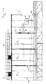
- the dryer 1 is supported at a distance above the floor via vertical support beams 20 and is stiffened by a frame construction 21 made of profile beams.
- a frame construction 21 made of profile beams.
- To this frame structure 21 include floor rails 22, floor cross members 23 and ceiling rails 24 and at each end of a unit E1 to E n arranged, the dryer profile corresponding connection frame 25 made of two corner beams 26, two rafters 27, a connector 28 and a cross member 29, which in particular figure 2 shows.
- the units E 1 to E n formed between the lead frames 25 can be further stiffened in a lighter design by similar intermediate frames 30.
- the transfer station 11 is stiffened and supported in a similar manner by profile beams. The same applies to the entry and discharge station 2. These stations 2 and 11 are separated by end walls 31 and 32 from the adjacent units E 1 and E n . The wall passage openings in these end walls 31, 32 are sealed in the area of the upper runs 9 and 16 by means of brush rollers 33. Furthermore, the drawings show that at the top of the dryer 1 over all units E1 to E n a walkable aisle 34 with side guards 35 extends.
- the dryer has an essentially building-like cross section, corresponding to its connecting frame 25.
- 2 shows an extension 36 on the left-hand side, in which heaters for heating the drying gas are arranged, this extension 36 is not specific to the invention, but can be dispensed with, as shown in FIGS. 3 to 7 with the dryer cross sections having a building profile.
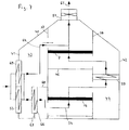
- FIGS. 3 to 7 show the typical design of the dryer 1 or its units E 1 to E n and the mode of operation of the dryer.
- the upper filter belt 7 and the lower drying belt 14 are between vertical side walls 37 and 38 arranged, which extend from the floor 39 to the roof 40.
- a vertical outer housing wall 41, 42 is arranged outside each side wall 37, 38 and extends from the floor 39 to the correspondingly lowered roof 40.
- a feed channel 43 and a transfer channel 44 are formed on opposite sides of the central dryer space delimited by the side walls 37 and 38.
- the central dryer space between the side walls 37 and 38 is through a bottom wall 45 and a partition 46, which extend horizontally between the side walls 37 and 38, and through the drying belt 14 and the filter belt 7 into a lower inlet chamber 47, a lower collecting chamber 48, an upper introduction chamber 49 and an upper collecting chamber 50 are divided. This is closed at its top by the roof 40 and leads to a fume cupboard 51 with a suction fan 52.
- This basic design is common to all the design variants according to FIGS. 3 to 7. These differ only with regard to the guidance of the drying gas (drying air) indicated by flow arrows and the number or arrangement of heaters.
- the air enters through a heater 53 built into the outer wall 41 of the housing and flows as drying gas 54 through a passage 54 in the side wall 37 into the lower inlet chamber 47 and through the drying belt 14 and the lower material layer 56 located thereon into the lower collecting chamber 48.
- a heater 53 built into the outer wall 41 of the housing and flows as drying gas 54 through a passage 54 in the side wall 37 into the lower inlet chamber 47 and through the drying belt 14 and the lower material layer 56 located thereon into the lower collecting chamber 48.
- the drying gas passes into the transfer duct 44 and from there into the upper introduction chamber 49.
- the drying gas passes through and is arranged between the openings 57 and 58 in the transfer duct 44 its cross-section filling intermediate heater 59.
- the reheated drying gas 54 flows through the filter belt 7 and the upper material layer 60 located thereon, impurities carried in the upper material layer 60 from the lower material layer 56 on the drying belt 14 largely be re-deposited.
- the upper conveyor belt is referred to as a filter belt, although here, too, a drying effect in connection with a Warming of the property takes place.
- the drying gas leaves the dryer 1 as exhaust 61 through the fume hood 51.
- FIG. 4 completely corresponds to the embodiment according to FIG. 3 described above, but the side wall 37 has a bypass opening 62 at the level of the upper collecting chamber 50, into which a control flap 63 is installed, which is shown in its open position. Accordingly, part of the air heated in the heater 53 flows directly into the upper collecting chamber 50 and bypasses the belts 7 and 14 and the material layers 56 and 60 as bypass gas 64 and is mixed with the exhaust gas 61.
- the transfer duct 44 is divided by a vertical intermediate wall 65, which extends from the floor 39 to the roof 40, a reheater 66 being installed in the intermediate wall 65. Accordingly, all of the air drawn in flows through the heater 53 and the reheater 66, in order then to be divided into the drying gas 54 passed through the belts 7 and 14 and the material layers 56 and 60 and the bypass gas 64 flowing to the upper collecting chamber 50.
- FIG. 6 largely corresponds to the embodiment according to FIG. 5, but intermediate heating of the drying gas 54 is dispensed with. Accordingly, the reheater 58, the partition 46 and the passage openings 56 and 57 are missing in the side wall 38.
- FIG. 7 corresponds to that according to FIG. 5 to the extent that the reheater 59 and the reheater 66 are also provided. However, the latter is only flowed through by the drying gas 54 led to the lower inlet chamber 47, so that instead of the intermediate wall 65 a lower connecting wall 67 and an upper connecting wall 68 are provided which connect the reheater 66 to the bottom 39 and to the side wall 37, respectively.
- an additional heater 69 is installed in the outer wall 41 of the housing and can be used specifically for heating the bypass gas 64 which is led directly to the upper collecting chamber 50.
Landscapes
- Engineering & Computer Science (AREA)
- Mechanical Engineering (AREA)
- General Engineering & Computer Science (AREA)
- Life Sciences & Earth Sciences (AREA)
- Microbiology (AREA)
- Drying Of Solid Materials (AREA)
Abstract
Description
Die Erfindung bezieht sich auf einen Trockner für schütt- oder rieselfähiges Gut, insbesondere Holzspäne, wie er im Oberbegriff des Anspruchs 1 beschrieben ist.The invention relates to a dryer for pourable or free-flowing material, in particular wood chips, as described in the preamble of
Ein solcher Trockner mit einem unteren Trocknungsband und einem oberen Filterband ist bekannt (DE 27 29 015 A). Dabei wird der Vorteil genutzt, daß von der aufsteigenden Trocknungsluft aus der Gutschicht auf dem Trocknungsband mitgeführte Verunreinigungen in der noch feuchteren Gutschicht auf dem Filterband weitgehend wieder abgelagert werden, so daß ggf. auf eine zusätzliche Reinigung des Trocknungsabgases bzw. der Abluft verzichtet werden kann.Such a dryer with a lower drying belt and an upper filter belt is known (DE 27 29 015 A). This takes advantage of the fact that impurities entrained by the rising drying air from the good layer on the drying belt are largely deposited again in the still wetter good layer on the filter belt, so that an additional cleaning of the drying exhaust gas or the exhaust air can possibly be dispensed with.
Der zum Nachtrocknen von Hopfen vorgesehene bekannte Trockner weist ein Gehäuse mit zwei entlang der Förderbandkanten verlaufenden Seitenwänden, zwei Stirnwänden und einem Dach auf, an das ein Kamin mit einem Saugzugventilator angeschlossen ist. Die Trocknungluft wird seitlich durch eine Rohrleitung von großem Querschnitt und und einen in diese Rohrleitung eingebauten Erhitzer zugeführt und dabei durch eine Seitenwandöffnung im wesentlichen in den Bereich zwischen Obertrum und Untertrum des Trocknungsbandes eingeleitet. Zur Überleitung der Trocknungsluft vom Trocknungsband zum Filterband ist über der Zuführungsleitung eine Rohrleitung von großem Querschnitt mit einem 180°-Bogen vorgesehen, die über zwei Seitenwandöffnungen den unteren Auffangraum über dem Trocknungsband mit dem Zwischenraum zwischen Obertrum und Untertrum des oberen Filterbandes verbindet.The known dryer provided for drying hops has a housing with two side walls running along the conveyor belt edges, two end walls and a roof to which a chimney with a suction fan is connected. The drying air is fed laterally through a pipeline of large cross-section and and a heater built into this pipeline, and is introduced through a side wall opening essentially into the area between the upper run and lower run of the drying belt. To transfer the drying air from the drying belt to the filter belt, a pipeline of large cross-section with a 180 ° bend is provided above the supply line, which connects the lower collecting space above the drying belt with the space between the upper run and lower run of the upper filter belt via two side wall openings.
Diese Ausbildung mit auf der selben Seite des Trockners angeordneter bodennaher Trocknungsluftzuführung und darüber befindlicher Trocknungsluftüberleitung in mittlerer Höhe ist raumaufwendig und ermöglicht wenig Gestaltungs- und Variationsmöglichkeiten des Trocknerbetriebes, da die gesamte Trocknungsluft bzw. vom Erhitzer gelieferte Trocknungswärme durch die Gutschicht auf dem Trocknungsband und durch die Gutschicht auf dem Filterband geleitet werden muß. Hinzu kommt die Gefahr, daß die Gutschicht auf dem Trocknungsband ungleichmäßig durchströmt und getrocknet wird, weil an der Seite, an der die Trocknungsluft zu- und abgeführt wird, mit einem erhöhten Trocknungsluftdurchsatz zu rechnen ist. Dementsprechend besteht die Tendenz zu örtlichen Übertrocknungen.This training, with the drying air supply on the same side of the dryer and the drying air conduit located above it at medium height, is space-consuming and allows little design and variation options for the dryer operation, since all of the drying air or drying heat supplied by the heater passes through the layer of material on the drying belt and through the Good layer must be passed on the filter belt. In addition, there is the risk that the material layer on the drying belt will be flowed through and dried unevenly because an increased drying air throughput is to be expected on the side on which the drying air is supplied and discharged. Accordingly, there is a tendency to overdry locally.
Der Erfindung liegt die Aufgabe zugrunde, einen gattungsgleichen Trockner besonders einfach und kompakt auszubilden, wobei verbesserte Anpassungsmöglichkeiten an den jeweiligen Einsatzfall und hinsichtlich der Betriebsweise des Trockners erzielt werden sollen.The invention has for its object to form a generic dryer particularly simple and compact, with improved adaptation options to the particular application and in terms of the operation of the dryer to be achieved.
Diese Aufgabe wird mit dem kennzeichnenden Merkmalen des Anspruchs 1 gelöst.This object is achieved with the characterizing features of
Durch die erfindungsgemäß im Abstand außerhalb der beiden Seitenwände vorgesehenen senkrechten Gehäuseaußenwände werden die Zuführung und die Überleitung des Trocknungsgases in das Trocknergehäuse integriert und entfallen gesonderte Rohrleitungen für die Zuführung und Überleitung, wobei der Trockner glatte Seitenabschlüsse aufweist. Die zentral angeordneten Förderbänder sind zu beiden Seiten von einem zwischen der Seitenwand und der Gehäuseaußenwand begrenzten Kanal flankiert, der sich im wesentlichen über die ganze Länge und Höhe des Trockners erstreckt und nicht nur dem integrierten Einbau von Erhitzern (Nacherhitzer, Zwischenerhitzer) dient sondern zugleich vielfältige Möglichkeiten für die den jeweiligen Gegebenheiten angepaßte Strömungsführung des Trocknungsgases liefert.Due to the vertical housing outer walls provided according to the invention at a distance outside the two side walls, the supply and the transfer of the drying gas are integrated into the dryer housing and separate pipes for the supply and transfer are omitted, the dryer having smooth side ends. The centrally arranged conveyor belts are flanked on both sides by a channel defined between the side wall and the outer wall of the housing, which extends essentially over the entire length and height of the dryer and not only serves the integrated installation of heaters (reheaters, reheaters) but also a variety of them Provides options for the flow of drying gas adapted to the particular circumstances.
So kann eine weitgehend gleichmäßige Durchströmung der Gutschichten auf dem Trocknungsband und auf dem Filterband erreicht werden. Insbesondere läßt sich auf einfache Weise ein Teil des erhitzten Trocknungsgases unter Umgehung der beiden Bänder bzw. der auf diesen transportierten Gutschichten in die obere Auffangkammer leiten, wozu es nur einer in entsprechender Höhenlage in der zuführungsseitigen Seitenwand angebrachten Durchtrittsöffnung bedarf, die mit einer Regelklappe ausgestattet sein kann. Mit dieser Maßnahme kann einer Dampfschwadenbildung im oder hinter dem Abzug vorgebeugt werden. Zugleich kann aber auch einem beispielsweise durch Abwärmenutzung vorgegebenen und zur Trocknungsgaserhitzung genutzten Abwärmeangebot entsprochen werden, ohne daß eine Überhitzung des zu trocknenden Guts in Kauf genommen werden muß. Im übrigen ist es ebenso einfach mittels einer in entsprechender Höhenlage in der einen oder anderen Seitenwand angeordneten Durchtrittsöffnung (mit Regelklappe) möglich, einen Teil des Trocknungsgases nur am Trocknungsband oder nur am Filterband vorbei zu leiten.In this way, a largely uniform flow through the layers of material on the drying belt and on the filter belt can be achieved. In particular, a part of the heated drying gas can be passed into the upper collecting chamber bypassing the two belts or the layers of material transported on them, for which purpose only one in a corresponding manner Elevation in the feed-side wall requires passage opening, which can be equipped with a control flap. With this measure, steam vapor formation in or behind the fume hood can be prevented. At the same time, however, it is also possible to comply with a waste heat supply that is predetermined, for example, by using waste heat and used for drying gas heating, without having to put up with overheating of the material to be dried. For the rest, it is just as easy, by means of a passage opening (with a control flap) arranged in one or the other side wall at a corresponding height, to direct a part of the drying gas past the drying belt or only the filter belt.
Das Umgehen des unteren Trocknungsbandes und des oberen Filterbandes mit einem Teil der erhitzten Trocknungsluft ist allerdings bereits bekannt (DE 40 22 702 C). Bei diesem für das Trocknen von Holzspänen vorgesehenen Trockner ist eine Umgehungsleitung mit einer eingebauten Regelklappe vorgesehen, die stirnseitig über den Trockner vorspringt. Auch die Überleitung des Trocknungsgases vom unteren Trocknungsband zum oberen Filterband erfolgt nicht etwa seitlich der Förderbänder, vielmehr steigt die Trocknungsluft unmittelbar hintereinander durch das Trocknungsband und das Filterband auf, ohne daß eine Zwischenerhitzung der Trocknungsluft erfolgt.Bypassing the lower drying belt and the upper filter belt with part of the heated drying air is, however, already known (
Zweckmäßige Ausgestaltungen und Weiterbildungen ergeben sich aus den Unteransprüchen.Appropriate refinements and developments result from the subclaims.
Dabei hat sich die Modulbauweise gemäß Anspruch 8 als besonders zweckmäßig erwiesen, weil dadurch die Anpassungsfähigkeit weiter gesteigert wird. Durch das in Bandförderrichtung erfolgende Aneinanderreihen mehrerer Einheiten mit gleichen Querschnittsabmessungen bleibt der Vorteil einer kompakten Bauweise mit glatter Umgrenzung erhalten, während den unterschiedlichsten Anforderungen hinsichtlich des Gutdurchsatzes, des Feuchtigkeitsentzugs, der Durchströmungsgeschwindigkeit durch die Gutschichten usw. entsprochen werden kann. Dies insbesondere deswegen, weil nicht jede Einheit in gleicher Weise ausgestattet sein muß. Beispielsweise kann für zwei benachbarte Einheiten nur ein Lufterhitzer, ein Zwischenerhitzer und ein Abzug vorgesehen sein, um die Durchströmgeschwindigkeit der Gutschichten zu halbieren und so das Mitreißen von insbesondere staubförmigen Gutteilchen herabzusetzen.The modular design according to claim 8 has proven to be particularly expedient because it further increases the adaptability. By lining up several units with the same cross-sectional dimensions in the belt conveying direction, the advantage of a compact design with a smooth boundary is retained, while the most varied requirements regarding material throughput, moisture removal, flow rate through the material layers, etc. can be met. This is particularly so because not every unit has to be equipped in the same way. For example, only one air heater, an intermediate heater and a fume hood can be provided for two adjacent units in order to halve the flow rate of the material layers and thus reduce the entrainment of particulate material particles in particular.
Ein Ausführungsbeispiel des erfindungsgemäßen Trockners sowie verschiedene Möglichkeiten der Trocknungsgasführung werden nachfolgend anhand einer schematischen Zeichnung näher erläutert. Es zeigen:
Figur 1- - unterteilt in Figuren 1a und 1b - die entgegengesetzten Enden des Trockners in einer zum Teil längsgeschnittenen Seitenansicht;
Figur 2- einen Querschnitt längs Linie II-II in
Figur 1; und Figuren 3 bis 7- vergrößerte Querschnitte
entsprechend Figur 2 unter Weglassung von Einzelheiten sowie mit unterschiedlicher Trocknungsgasführung und unterschiedlicher Bestückung mit Wärmetauschern.
- Figure 1
- - divided into Figures 1a and 1b - the opposite ends of the dryer in a partially longitudinally sectioned side view;
- Figure 2
- a cross section along line II-II in Figure 1; and
- Figures 3 to 7
- enlarged cross sections according to Figure 2 with omission of details and with different drying gas and different equipment with heat exchangers.
Gemäß Figuren 1a und 1b besteht der Trockner 1 aus einer Reihe von Einheiten E₁ bis En, die jeweils gleiche Länge und auch im wesentlichen gleiche Querschnittsabmessungen aufweisen und in einer Reihe unmittelbar aneinander anschließend angeordnet sind. Am Anfang dieser Reihe ist eine Eintrags- und Austragsstation 2 vorgesehen, die einen über ein Füllrohr 3 beschickbaren Hochbunker 4 für das zu trocknende Gut (Holzspäne) aufweist. Über eine Entnahmeschnecke 5 und einen Verteiler 6 in Form einer Doppelschneckenanordnung wird das Gut in einer gleichmäßig dicken Schicht auf ein umlaufendes endloses Filterband 7 aufgebracht, das sich durch sämtliche Einheiten E₁ bis En erstreckt und durch einen Antriebsmotor 8 angetrieben wird. Dabei bewegt sich das fördernde Obertrum 9 in der Förderrichtung 10.According to Figures 1a and 1b, the
An die letzte Einheit En schließt sich eine Überleitungsstation 11 an, die einen Auffangbehälter 12 für das an der Filterbandumlenkung abgeworfene Gut mit einem Verteiler 13 in Form einer Doppelschneckenanordnung aufweist, der das Gut in einer gleichmäßigen Schicht auf ein Trocknungsband 14 aufbringt, das im Abstand unterhalb des Filterbands 7 durch sämtliche Einheiten E₁ bis En hindurch zur Eintrags- und Austragsstation 2 zurückführt. Das endlose Trocknungsband 14 wird durch einen Antriebsmotor 15 angetrieben, wobei sein förderndes Obertrum 16 sich in der Förderrichtung 17 bewegt.The last unit E n is followed by a
Der Abwurfstelle des Trocknungsbandes 14 in der Eintrags- und Austragsstation 2 ist ein Auffangbehälter 18 zugeordnet, aus dem das getrocknete bzw. vorgetrocknete Gut über eine Doppelschneckenanordnung 19 der weiteren Verwendung, beispielsweise im Rahmen der Spanplattenherstellung, zugeführt wird.The discharge point of the
Wie die Figuren 1 und 2 zeigen, ist der Trockner 1 über senkrechte Stützträger 20 im Abstand über dem Boden abgestützt und durch eine Rahmenkonstruktion 21 aus Profilträgern versteift ist. Zu dieser Rahmenkonstruktion 21 gehören Bodenlängsträger 22, Bodenquerträger 23 und Deckenlängsträger 24 sowie an jedem Ende einer Einheit E₁ bis En angeordnete, dem Trocknerprofil entsprechende Anschlußrahmen 25 aus zwei Eckträgern 26, zwei Sparren 27, einem Verbinder 28 und einem Querträger 29, was insbesondere Figur 2 zeigt. Wie aus Figur 1 zu ersehen können die zwischen den Anschlußrahmen 25 ausgebildeten Einheiten E₁ bis En durch ähnliche Zwischenrahmen 30 in leichterer Ausführung weiter versteift sein.As FIGS. 1 and 2 show, the
Die Überleitungsstation 11 ist in ähnlicher Weise durch Profilträger versteift und abgestützt. Entsprechendes gilt für die Eintrags- und Austragsstation 2. Dabei sind diese Stationen 2 und 11 durch Stirnwände 31 und 32 von den benachbarten Einheiten E₁ bzw. En abgetrennt. Die Wanddurchgangsöffnungen in diesen Stirnwänden 31, 32 sind im Bereich der Obertrume 9 und 16 mittels Bürstenwalzen 33 abgedichtet. Ferner ist den Zeichnungen zu entnehmen, daß an der Oberseite des Trockners 1 über sämtliche Einheiten E₁ bis En hinweg ein begehbarer Gang 34 mit seitlichen Schutzgittern 35 verläuft.The
Gemäß Figur 2 weist der Trockner entsprechend seinen Anschlußrahmen 25 einen im wesentlichen gebäudeartigen Querschnitt auf. Zwar zeigt Figur 2 linksseitig einen Anbau 36, in dem Erhitzer zur Erwärmung des Trocknungsgases angeordnet sind, dieser Anbau 36 ist jedoch nicht erfindungsspezifisch, vielmehr kann darauf verzichtet werden, wie es die Figuren 3 bis 7 mit den ein Gebäudeprofil aufweisenden Trocknerquerschnitten deutlich machen. Diese Figuren zeigen am besten die typische Ausbildung des Trockners 1 bzw. seiner Einheiten E₁ bis En sowie die Betriebsweise des Trockners.According to FIG. 2, the dryer has an essentially building-like cross section, corresponding to its connecting
Danach sind jeweils das obere Filterband 7 und das untere Trocknungsband 14 zwischen senkrechten Seitenwänden 37 und 38 angeordnet, die sich vom Boden 39 bis zum Dach 40 erstrecken. Mit Seitenabstand ist außerhalb einer jeden Seitenwand 37, 38 eine senkrechte Gehäuseaußenwand 41, 42 angeordnet, die sich vom Boden 39 bis zu dem entprechend weit herabgeführten Dach 40 erstreckt. Auf diese Weise sind auf gegenüberliegenden Seiten des durch die Seitenwände 37 und 38 begrenzten zentralen Trocknerraums ein Zuführungskanal 43 und ein Überleitungskanal 44 gebildet.Thereafter, the
Der zentrale Trocknerraum zwischen den Seitenwänden 37 und 38 ist durch eine Bodenwand 45 und eine Trennwand 46, die sich waagerecht zwischen den Seitenwänden 37 und 38 erstrecken, sowie durch das Trocknungsband 14 und das Filterband 7 in eine untere Einleitungskammer 47, eine untere Auffangkammer 48, eine obere Einleitungskammer 49 und eine obere Auffangkammer 50 unterteilt. Diese ist an ihrer Oberseite durch das Dach 40 abgeschlossen und führt zu einem Abzug 51 mit einem Saugzugventilator 52. Diese Grundausbildung ist allen Ausführungsvarianten gemäß Figuren 3 bis 7 gemeinsam. Diese unterscheiden sich nur hinsichtlich der durch Strömungspfeile angedeuteten Führung des Trocknungsgases (Trocknungsluft) und der Zahl bzw. Anordnung von Erhitzern.The central dryer space between the
Gemäß Figur 3 tritt die Luft durch einen in die Gehäuseaußenwand 41 eingebauten Erhitzer 53 ein und strömt als Trocknungsgas 54 durch eine Durchtrittsöffnung 54 der Seitenwand 37 in die untere Einleitungskammer 47 sowie durch das Trocknungsband 14 und die auf diesem befindliche untere Gutschicht 56 in die untere Auffangkammer 48. Durch zwei in der Seitenwand 38 in entsprechender Höhe vorgesehene Durchtrittsöffnungen 57 und 58 tritt die Trocknungsgas in den Überleitungskanal 44 über und gelangt von diesem in die obere Einleitungskammer 49. Dabei passiert das Trocknungsgas einen zwischen den Öffnungen 57 und 58 im Überleitungskanal 44 angeordneten und dessen Querschnitt ausfüllenden Zwischenerhitzer 59. Von der oberen Einleitungskammer 49 strömt das wiedererwärmte Trocknungsgas 54 durch das Filterband 7 und die auf diesem befindliche obere Gutschicht 60, wobei aus der unteren Gutschicht 56 auf dem Trocknungsband 14 mitgeführte Verunreinigungen in der oberen Gutschicht 60 weitgehend wieder abgeschieden werden. Aus diesem Grunde wird das obere Förderband als Filterband bezeichnet, obwohl hier ebenfalls bereits eine Trocknungswirkung in Verbindung mit einer Erwärmung des Guts stattfindet. Schließlich verläßt das Trocknungsgas als Abgas 61 den Trockner 1 durch den Abzug 51.According to FIG. 3, the air enters through a
Die Ausführung nach Figur 4 stimmt mit der vorbeschriebenen Ausführung nach Figur 3 vollständig überein, jedoch weist die Seitenwand 37 in Höhe der oberen Auffangkammer 50 eine Umgehungsöffnung 62 auf, in die eine Regelklappe 63 eingebaut ist, die in Ihrer Offenstellung dargestellt ist. Dementsprechend strömt ein Teil der im Erhitzer 53 erwärmten Luft unter Umgehung der Bänder 7 und 14 sowie der Gutschichten 56 und 60 als Umgehungsgas 64 direkt in die obere Auffangkanmmer 50 und wird dem Abgas 61 beigemischt.The embodiment according to FIG. 4 completely corresponds to the embodiment according to FIG. 3 described above, but the
In Figur 5 ist zusätzlich zur Ausführung nach Figur 4 der Überleitungskanal 44 durch eine senkrechte Zwischenwand 65, die sich vom Boden 39 bis zum Dach 40 erstreckt, unterteilt, wobei in die Zwischenwand 65 ein Nacherhitzer 66 eingebaut ist. Dementsprechend strömt die gesamte angesaugte Luft durch den Erhitzer 53 und den Nacherhitzer 66, um sich dann in das durch die Bänder 7 und 14 sowie die Gutschichten 56 und 60 geleitete Trocknungsgas 54 und das zur oberen Auffangkammer 50 strömende Umgehungsgas 64 aufzuteilen.In FIG. 5, in addition to the embodiment according to FIG. 4, the
Figur 6 stimmt weitgehend mit der Ausführung nach Figur 5 überein, jedoch wird auf eine Zwischenerhitzung des Trocknungsgases 54 verzichtet. Dementsprechend fehlen der Zwischenerhitzer 58, die Trennwand 46 und die Durchtrittsöffnungen 56 und 57 in der Seitenwand 38.FIG. 6 largely corresponds to the embodiment according to FIG. 5, but intermediate heating of the drying
Die Ausführung gemäß Figur 7 entspricht derjenigen nach Figur 5 insoweit, daß ebenfalls der Zwischenerhitzer 59 und der Nacherhitzer 66 vorgesehen sind. Letzerer wird aber nur vom zur unteren Einleitungskammer 47 geführten Trocknungsgas 54 durchströmt, so daß anstelle der Zwischenwand 65 eine untere Verbindungswand 67 und eine obere Verbindungswand 68 vorgesehen sind, die den Nacherhitzer 66 mit dem Boden 39 bzw. mit der Seitenwand 37 verbinden. Ferner ist in die Gehäuseaußenwand 41 außer dem Erhitzer 53 ein Zusatzerhitzer 69 eingebaut, der speziell zur Erwärmung des direkt zur oberen Auffangkammer 50 geführten Umgehungsgases 64 eingesetzt werden kann.The embodiment according to FIG. 7 corresponds to that according to FIG. 5 to the extent that the
Bei einer Ausführung mit mehreren Wärmetauschern (Erhitzer 53, Zwischenerhitzer 59, Nacherhitzer 66, Zusatzerhitzer 69) werden diese vorzugsweise der Reihe nach von einem Wärme liefernden Wärmeträger durchströmt, und zwar in der Reihenfolge Zwischenerhitzer 59, Nacherhitzer 66, Erhitzer 53 und Zusatzerhitzer 69. So lassen sich besonders günstige Temperaturbedingungen und eine große Temperaturabsenkung des Wärmeträgers erreichen, der beispielsweise Abwärme aus einem anderen Prozeß zur Verfügung stellt.With a version with several heat exchangers (
Es ist nicht notwendig, daß alle Einheiten E₁ bis En des Trockners 1 als komplette Einheiten wie anhand von Figuren 3 bis 7 beschrieben ausgestattet sind. Da benachbarte Einheiten in Förderrichtung 10 bzw. 17 miteinander in Strömungsverbindung stehen können, lassen sich einzelne Einheiten ohne die vorbeschriebenen Ausstattungsmerkmale wie Erhitzer, Zwischenerhitzer, Nacherhitzer, Umgehungsöffnung, Regelklappe oder Abzug ausführen, wobei dann diese Einheiten durch andere (benachbarte) Einheiten mitversort werden. In diesem Sinne ist auf Figur 1 hinzuweisen, wonach die Einheiten E₁ und En ohne Abzug 51 dargestellt sind. Gegebenenfalls können nicht nur teilbestückte Einheiten sondern regelrechte Leereinheiten eingebaut werden, wodurch sich erweiterte Möglichkeiten zur nachträglichen Anpassung des Trockners ergeben.It is not necessary that all
Claims (12)
Applications Claiming Priority (2)
| Application Number | Priority Date | Filing Date | Title |
|---|---|---|---|
| DE4217056 | 1992-05-22 | ||
| DE19924217056 DE4217056A1 (en) | 1992-05-22 | 1992-05-22 | Dryer for pourable or pourable goods |
Publications (1)
| Publication Number | Publication Date |
|---|---|
| EP0570970A1 true EP0570970A1 (en) | 1993-11-24 |
Family
ID=6459547
Family Applications (1)
| Application Number | Title | Priority Date | Filing Date |
|---|---|---|---|
| EP93108268A Withdrawn EP0570970A1 (en) | 1992-05-22 | 1993-05-21 | Dryer for bulk or pourable materials |
Country Status (2)
| Country | Link |
|---|---|
| EP (1) | EP0570970A1 (en) |
| DE (1) | DE4217056A1 (en) |
Cited By (2)
| Publication number | Priority date | Publication date | Assignee | Title |
|---|---|---|---|---|
| EP2650632A1 (en) * | 2012-04-13 | 2013-10-16 | Aqualogy Development Network, S.A. | Multiple product belt drier for drying pasty and/or powdery materials, particularly for drying sludges from treatment plants or biomass |
| CN112138475A (en) * | 2020-09-30 | 2020-12-29 | 中冶焦耐(大连)工程技术有限公司 | Distributed dust removal system for smoke dissipated by coke oven and working method thereof |
Families Citing this family (1)
| Publication number | Priority date | Publication date | Assignee | Title |
|---|---|---|---|---|
| US5813138A (en) * | 1996-12-19 | 1998-09-29 | Barabe; Richard | Aerated belt conveyor system for conveying hot expanded minerals |
Citations (8)
| Publication number | Priority date | Publication date | Assignee | Title |
|---|---|---|---|---|
| US2259963A (en) * | 1937-11-17 | 1941-10-21 | Surico Carmine | Dough product drier |
| CH300111A (en) * | 1950-07-07 | 1954-07-15 | Borie Jean Victor Roger | Device for drying a product. |
| US3143398A (en) * | 1962-09-14 | 1964-08-04 | Challenge Cook Bros Inc | Sealed apparatus for drying, warming and aerating materials |
| DE2731555A1 (en) * | 1976-07-16 | 1978-01-19 | Jean Duperret | DEVICE FOR AUTOMATIC DRYING OF PRODUCTS |
| DE2729015A1 (en) * | 1977-06-28 | 1979-01-04 | Lupofresh Allfeld & Egloff Kg | PROCESS FOR AFTER-DRYING HOP AND HOP PRODUCT |
| FR2480418A1 (en) * | 1980-04-10 | 1981-10-16 | Agei | Low temperature dryer with two compartments - has heated air flowing through both sections with articles travelling on conveyor with serpentine path of travel |
| WO1989005949A1 (en) * | 1986-11-20 | 1989-06-29 | Bertin & Cie | Industrial installation for drying a moist product with at least partial recirculation of a drying fluid |
| DE4022702C1 (en) * | 1990-07-17 | 1991-11-28 | Fritz Egger Ges.M.B.H., Sankt Johann In Tirol, At |
-
1992
- 1992-05-22 DE DE19924217056 patent/DE4217056A1/en not_active Withdrawn
-
1993
- 1993-05-21 EP EP93108268A patent/EP0570970A1/en not_active Withdrawn
Patent Citations (8)
| Publication number | Priority date | Publication date | Assignee | Title |
|---|---|---|---|---|
| US2259963A (en) * | 1937-11-17 | 1941-10-21 | Surico Carmine | Dough product drier |
| CH300111A (en) * | 1950-07-07 | 1954-07-15 | Borie Jean Victor Roger | Device for drying a product. |
| US3143398A (en) * | 1962-09-14 | 1964-08-04 | Challenge Cook Bros Inc | Sealed apparatus for drying, warming and aerating materials |
| DE2731555A1 (en) * | 1976-07-16 | 1978-01-19 | Jean Duperret | DEVICE FOR AUTOMATIC DRYING OF PRODUCTS |
| DE2729015A1 (en) * | 1977-06-28 | 1979-01-04 | Lupofresh Allfeld & Egloff Kg | PROCESS FOR AFTER-DRYING HOP AND HOP PRODUCT |
| FR2480418A1 (en) * | 1980-04-10 | 1981-10-16 | Agei | Low temperature dryer with two compartments - has heated air flowing through both sections with articles travelling on conveyor with serpentine path of travel |
| WO1989005949A1 (en) * | 1986-11-20 | 1989-06-29 | Bertin & Cie | Industrial installation for drying a moist product with at least partial recirculation of a drying fluid |
| DE4022702C1 (en) * | 1990-07-17 | 1991-11-28 | Fritz Egger Ges.M.B.H., Sankt Johann In Tirol, At |
Cited By (5)
| Publication number | Priority date | Publication date | Assignee | Title |
|---|---|---|---|---|
| EP2650632A1 (en) * | 2012-04-13 | 2013-10-16 | Aqualogy Development Network, S.A. | Multiple product belt drier for drying pasty and/or powdery materials, particularly for drying sludges from treatment plants or biomass |
| WO2013153248A1 (en) | 2012-04-13 | 2013-10-17 | Aqualogy Development Network, S.A. | Multiple product belt drier for drying pasty and/or powdery materials, particularly for drying sludges from treatment plants or biomass |
| US9939199B2 (en) | 2012-04-13 | 2018-04-10 | Sociedad General De Aguas De Barcelona, S.A. | Multiple product belt drier for drying pasty and/or powdery materials, particularly for drying sludges from treatment plants or biomass |
| CN112138475A (en) * | 2020-09-30 | 2020-12-29 | 中冶焦耐(大连)工程技术有限公司 | Distributed dust removal system for smoke dissipated by coke oven and working method thereof |
| CN112138475B (en) * | 2020-09-30 | 2024-01-30 | 中冶焦耐(大连)工程技术有限公司 | Coke oven dissipation smoke dust distributed dust removal system and working method thereof |
Also Published As
| Publication number | Publication date |
|---|---|
| DE4217056A1 (en) | 1993-11-25 |
Similar Documents
| Publication | Publication Date | Title |
|---|---|---|
| DE4218699C2 (en) | Flow dryer for drying sludge with filter arrangement | |
| DE2443589C2 (en) | Water cooling tower | |
| DE3934513A1 (en) | EXHAUST AIR PLANT | |
| EP1080788B1 (en) | Cooling zone of a painting installation and method for operating such a cooling zone | |
| EP2244840B2 (en) | Device and method for supplying air to an application zone of a paint booth | |
| WO1988005258A1 (en) | Cages for poultry raising | |
| DE10100895C2 (en) | Plant for extracting air pollution in the manufacture of wood-based panels, in particular MDF, chipboard or the like. | |
| DE2627262C3 (en) | Device for drying solids transported by a flowing gas | |
| DE102008013713A1 (en) | paint shop | |
| EP0570970A1 (en) | Dryer for bulk or pourable materials | |
| CH660286A5 (en) | PLANT AND THEIR USE FOR DRYING TOBACCO PARTICLES. | |
| EP0382742B1 (en) | Process of guiding a stream of bulk solids in at least one circulating bed reactor and reactor installation for realising the process | |
| EP0410098B1 (en) | Modular special climate room system | |
| EP0255555B1 (en) | Apparatus for continuously washing a felted fibrous material, more particularly comminuted sugar cane | |
| DE2151844C2 (en) | Method and device for conditioning tobacco | |
| DE4442538C2 (en) | Double-strand cigarette manufacturing apparatus | |
| EP3640572A2 (en) | Method and drying installation for wet wood and the like with improved exhaust quality | |
| DE6938007U (en) | MOVABLE HOOD FOR PAPER MACHINES. | |
| DE2206799A1 (en) | Ventilation device for cattle stalls | |
| DE60012902T2 (en) | DRYING DEVICE | |
| DE2818546C2 (en) | Plant for the continuous production of polyurethane foam blocks | |
| EP0621248A1 (en) | Device for composting organic wastes | |
| DD147402A5 (en) | METHOD AND APPARATUS FOR DRYING PRODUCTS | |
| DE2625658C2 (en) | Vacuum dryer for free-flowing products | |
| EP3913311A1 (en) | Method for drying bulk material |
Legal Events
| Date | Code | Title | Description |
|---|---|---|---|
| PUAI | Public reference made under article 153(3) epc to a published international application that has entered the european phase |
Free format text: ORIGINAL CODE: 0009012 |
|
| AK | Designated contracting states |
Kind code of ref document: A1 Designated state(s): AT DE DK FR GB IE |
|
| 17P | Request for examination filed |
Effective date: 19940524 |
|
| 17Q | First examination report despatched |
Effective date: 19950726 |
|
| GRAG | Despatch of communication of intention to grant |
Free format text: ORIGINAL CODE: EPIDOS AGRA |
|
| RAP1 | Party data changed (applicant data changed or rights of an application transferred) |
Owner name: FRITZ EGGER GESELLSCHAFT M.B.H. & CO |
|
| GRAH | Despatch of communication of intention to grant a patent |
Free format text: ORIGINAL CODE: EPIDOS IGRA |
|
| GRAH | Despatch of communication of intention to grant a patent |
Free format text: ORIGINAL CODE: EPIDOS IGRA |
|
| STAA | Information on the status of an ep patent application or granted ep patent |
Free format text: STATUS: THE APPLICATION IS DEEMED TO BE WITHDRAWN |
|
| 18D | Application deemed to be withdrawn |
Effective date: 19971202 |