EP0570620B1 - Dispositif pour la fixation d'un plateau de support rigide à une surface d'un meuble - Google Patents
Dispositif pour la fixation d'un plateau de support rigide à une surface d'un meuble Download PDFInfo
- Publication number
- EP0570620B1 EP0570620B1 EP92115407A EP92115407A EP0570620B1 EP 0570620 B1 EP0570620 B1 EP 0570620B1 EP 92115407 A EP92115407 A EP 92115407A EP 92115407 A EP92115407 A EP 92115407A EP 0570620 B1 EP0570620 B1 EP 0570620B1
- Authority
- EP
- European Patent Office
- Prior art keywords
- anchoring part
- plate
- anchoring
- holding plate
- retention plate
- Prior art date
- Legal status (The legal status is an assumption and is not a legal conclusion. Google has not performed a legal analysis and makes no representation as to the accuracy of the status listed.)
- Expired - Lifetime
Links
- 238000004873 anchoring Methods 0.000 claims abstract description 93
- 239000004033 plastic Substances 0.000 claims description 40
- 239000000853 adhesive Substances 0.000 claims description 33
- 230000001070 adhesive effect Effects 0.000 claims description 33
- 239000002904 solvent Substances 0.000 claims description 6
- 238000006073 displacement reaction Methods 0.000 claims description 3
- 230000014759 maintenance of location Effects 0.000 claims 12
- 238000010276 construction Methods 0.000 claims 1
- 238000003780 insertion Methods 0.000 description 10
- 230000037431 insertion Effects 0.000 description 10
- 239000000463 material Substances 0.000 description 5
- 239000012790 adhesive layer Substances 0.000 description 4
- 238000004519 manufacturing process Methods 0.000 description 2
- 238000000926 separation method Methods 0.000 description 2
- 239000002313 adhesive film Substances 0.000 description 1
- 238000005452 bending Methods 0.000 description 1
- 230000000694 effects Effects 0.000 description 1
- 238000005516 engineering process Methods 0.000 description 1
- 239000003000 extruded plastic Substances 0.000 description 1
- 239000003292 glue Substances 0.000 description 1
- 239000002184 metal Substances 0.000 description 1
- 230000002093 peripheral effect Effects 0.000 description 1
- 239000011148 porous material Substances 0.000 description 1
- 239000004753 textile Substances 0.000 description 1
Images


Classifications
-
- A—HUMAN NECESSITIES
- A47—FURNITURE; DOMESTIC ARTICLES OR APPLIANCES; COFFEE MILLS; SPICE MILLS; SUCTION CLEANERS IN GENERAL
- A47B—TABLES; DESKS; OFFICE FURNITURE; CABINETS; DRAWERS; GENERAL DETAILS OF FURNITURE
- A47B21/00—Tables or desks for office equipment, e.g. typewriters, keyboards
- A47B21/03—Tables or desks for office equipment, e.g. typewriters, keyboards with substantially horizontally extensible or adjustable parts other than drawers, e.g. leaves
-
- F—MECHANICAL ENGINEERING; LIGHTING; HEATING; WEAPONS; BLASTING
- F16—ENGINEERING ELEMENTS AND UNITS; GENERAL MEASURES FOR PRODUCING AND MAINTAINING EFFECTIVE FUNCTIONING OF MACHINES OR INSTALLATIONS; THERMAL INSULATION IN GENERAL
- F16B—DEVICES FOR FASTENING OR SECURING CONSTRUCTIONAL ELEMENTS OR MACHINE PARTS TOGETHER, e.g. NAILS, BOLTS, CIRCLIPS, CLAMPS, CLIPS OR WEDGES; JOINTS OR JOINTING
- F16B12/00—Jointing of furniture or the like, e.g. hidden from exterior
- F16B12/10—Jointing of furniture or the like, e.g. hidden from exterior using pegs, bolts, tenons, clamps, clips, or the like
- F16B12/12—Jointing of furniture or the like, e.g. hidden from exterior using pegs, bolts, tenons, clamps, clips, or the like for non-metal furniture parts, e.g. made of wood, of plastics
-
- F—MECHANICAL ENGINEERING; LIGHTING; HEATING; WEAPONS; BLASTING
- F16—ENGINEERING ELEMENTS AND UNITS; GENERAL MEASURES FOR PRODUCING AND MAINTAINING EFFECTIVE FUNCTIONING OF MACHINES OR INSTALLATIONS; THERMAL INSULATION IN GENERAL
- F16B—DEVICES FOR FASTENING OR SECURING CONSTRUCTIONAL ELEMENTS OR MACHINE PARTS TOGETHER, e.g. NAILS, BOLTS, CIRCLIPS, CLAMPS, CLIPS OR WEDGES; JOINTS OR JOINTING
- F16B12/00—Jointing of furniture or the like, e.g. hidden from exterior
- F16B12/40—Joints for furniture tubing
- F16B12/42—Joints for furniture tubing connecting furniture tubing to non-tubular parts
-
- A—HUMAN NECESSITIES
- A47—FURNITURE; DOMESTIC ARTICLES OR APPLIANCES; COFFEE MILLS; SPICE MILLS; SUCTION CLEANERS IN GENERAL
- A47B—TABLES; DESKS; OFFICE FURNITURE; CABINETS; DRAWERS; GENERAL DETAILS OF FURNITURE
- A47B37/00—Tables adapted for other particular purposes
- A47B2037/005—Tables specially adapted for laboratories
-
- A—HUMAN NECESSITIES
- A47—FURNITURE; DOMESTIC ARTICLES OR APPLIANCES; COFFEE MILLS; SPICE MILLS; SUCTION CLEANERS IN GENERAL
- A47B—TABLES; DESKS; OFFICE FURNITURE; CABINETS; DRAWERS; GENERAL DETAILS OF FURNITURE
- A47B2200/00—General construction of tables or desks
- A47B2200/0084—Accessories for tables or desks
- A47B2200/0085—Supplementary support fixed on the edge of a desk or table
Definitions
- the invention relates to a device for fastening a resilient, rigid holding plate to a furniture surface according to the preamble of patent claim 1.
- a holding plate is placed flat on a table top and fastened to it by means of a textile adhesive fastener, part of which is glued to the table top.
- the holding plate carries a vertical support column which is suitable for accommodating different functional elements, for example the plate of a standing desk, a display support, a telephone arm, a lamp or the like. This means that any desks and work tables can be retrofitted using the vertical support column.
- the attachment of the holding plate on the table top has the advantage over conventional clamping devices that the attachment is independent of the shape of the table top and the furniture.
- this type of attachment can be used with any thickness of the table top, with any edge shape of the table top and also with the table top not protruding beyond the body.
- the holding plate can be removed from the furniture surface without damaging it.
- the rigid holding plate is first cut off in the area of the adhesive fastener. Then the part of the adhesive fastener glued onto the furniture surface can be separated from the furniture surface. Since this part is flexible, it can be carefully removed from the furniture surface without damaging it. This would be difficult if the rigid holding plate were glued directly onto the furniture surface, since the adhesive connection would have to be torn off over the entire adhesive surface at the same time.
- the invention is based on the problem of creating a device for fastening a rigid holding plate to a furniture surface, which combines high resilience with simple releasability of the fastening.
- the holding plate is fastened to the furniture surface, for example on the table top of a work or desk.
- the holding plate does not protrude beyond the edge of the furniture surface, so that attachment to any furniture surface, regardless of the shape of the piece of furniture, and in any area of the furniture surface is possible. All advantages of the known fastening are thus fulfilled in the same way.
- An anchoring part is glued onto the furniture surface, for which purpose a releasable adhesive is preferably used.
- the holding plate is positively attached to this anchoring part.
- the interlocking locking of the rigid holding plate to the anchoring part enables the holding plate to be easily attached to the anchoring part and also an easy release of the holding plate from the anchoring part.
- the anchoring part itself which is preferably in the form of an anchoring plate, can be resiliently flexible, deformable or flexible, so that it can be detached from the furniture surface relatively easily if required, starting from an edge or a corner is successively separated and peeled off. If necessary, a solvent can also be applied.
- the anchoring part As soon as the rigid cold plate is connected to the anchoring part, the anchoring part is completely stiffened by the holding plate, so that it is no longer possible to bend or deform the anchoring part.
- the adhesive connection between the anchoring part and the furniture surface can therefore no longer be detached progressively along a dividing line when the holding plate is attached, but a separation of the adhesive connection would only be possible over the entire surface of the adhesive connection at the same time.
- the adhesive attachment of the holding plate can absorb a high load, particularly due to tilting moments.
- the positive connection of the holding plate with the anchoring part enables the holding plate to be easily removed if the holding plate and the functional elements attached to it are to be removed for a short time or if a holding plate with one functional element is to be exchanged for a holding plate with another functional element. If the device is to be completely removed, then after the positive connection has been disconnected and after the rigid holding plate has been removed, the anchoring part, which is then freely accessible and is no longer stiffened by the rigid holding plate, is detached from the furniture surface, the anchoring part being carefully peeled off and along a moving dividing line can be separated. If necessary, a solvent for the adhesive used can be applied through the anchoring part onto the entire adhesive surface or along the respective dividing line between the anchoring part and the furniture surface.
- the positive connection and locking of the holding plate and anchoring part can be realized in many ways.
- the anchoring part is preferably designed as an anchoring plate on which the holding plate is placed flat. Protrusions and receptacles of the surfaces of the anchoring plate and the holding plate which sit on one another engage in a form-fitting manner in this case.
- the holding plate can thus be placed on the anchoring plate glued to the furniture surface and locked by sliding.
- the anchoring part is completely covered by the holding plate, so that the fastening measures are invisible and an elegant appearance is guaranteed.
- a large-area anchoring plate is provided.
- the anchoring plate is divided by predetermined breaking lines. As long as the anchoring plate is stiffened by the rigid holding plate, these predetermined breaking lines are ineffective and the entire surface of the anchoring plate acts as a continuous surface of the adhesive connection. If the holding plate is removed, the anchoring plate can be detached separately from the furniture surface in the individual areas divided by the predetermined breaking lines, so that there is in each case a smaller adhesive surface and thus an easier detachment.
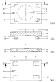
- a vertical support column 12 is to be attached to a furniture surface 10, for example the worktop of a desk.
- the support column 12 serves to carry functional elements, e.g. a standing desk top, a screen arm, a telephone arm, a table lamp or the like.
- a horizontal rigid holding plate 14 is attached at the lower end of the support column 12.
- the support column 12 and the holding plate 14 consist of a suitable material, for example cast metal or plastic.
- An anchoring part in the form of an anchoring plate 16 is glued onto the furniture surface 10.
- An adhesive applied on one side to the underside of the anchoring plate 16 or a double-sided adhesive film can be used to glue the anchoring plate 16 on.
- the holding plate 14 and the anchoring plate 16 have the same area, so that when the holding plate 14 is placed on the anchoring plate 16, these two plates visually connect to form a uniform plate.
- the surface dimensions of the holding plate 14 and the anchoring plate 16 are chosen such that there is sufficient support for the support column 12, in particular against tilting moments.
- the holding plate 14 and the anchoring plate 16 can accordingly be triangular, rectangular and in particular have square shapes, as shown in the drawing.
- the holding plate 14 and the anchoring plate 16 can also be formed from two or more rails arranged on the furniture surface 10 and arranged at an angle, preferably a right angle .
- the anchoring plate 16 is preferably made of an elastic plastic material, so that a deflection of the anchoring plate 16 is possible. This makes it easier to detach the anchoring plate 16 from the furniture surface 10.
- the anchoring plate 16 can be lifted off the furniture surface 10 at one of its corners and then progressively peeled off the furniture surface 10 with bending. The bonding of the anchoring plate 16 to the furniture surface 10 is progressively separated in each case only along one line. This means that less effort is required to detach it and the furniture surface 10 is protected.
- a soluble adhesive is preferably used to adhere the anchor plate 16. If the anchoring plate 16 is to be detached, a solvent can first be applied to facilitate detachment. In order to bring the solvent to the adhesive surface, the anchoring plate 16 can optionally consist of a porous material or have openings through which the solvent can reach the adhesive surface.
- the holding plate 14 is positively attached to the anchoring plate 16.
- the holding plate 14 has on its underside projections 18 which engage positively in receptacles 20 of the anchoring plate 16.
- the number of projections 18 and the receptacles 20 depends on the Size and shape of the holding plate 14 and the anchoring plate 16 from and also from the tilting load to be absorbed by the support column 12.
- the holding plate 14 and the anchoring plate 16 are of rectangular design and a projection 18 and a corresponding receptacle 20 are assigned to each corner.
- the projections 18 of the holding plate 14 each consist of a rectangular block 22 projecting perpendicularly from the underside of the holding plate 14, on the lower end of which a nose 24 projects on one side parallel to the plane of the holding plate.
- the lugs 24 of all the projections 18 point in the same direction.
- the receptacles 20 of the anchoring plate 16 corresponding to the protrusions 18 have an insertion opening 26 which passes through the anchoring plate 16 and whose cross section corresponds to the cross section of the surface of block 22 and nose 24 of the protrusions 18.
- an undercut 28 for the lugs 24 of the projections 18 adjoins the insertion openings 26.
- the undercuts 28 are open on the underside of the anchoring plate 16, so that the anchoring plate 16 with the undercuts 28 is easy to manufacture in terms of production technology.
- the holding plate 14 To fasten the holding plate 14 to the anchoring plate 16, the holding plate 14 is placed on the anchoring plate 16 from above, the projections 18 being inserted into the insertion openings 26 of the receptacles 20. As soon as the holding plate 14 lies flat on the anchoring plate 16, the holding plate 14 becomes on the anchoring plate 16 shifted (to the right in the illustration of FIGS. 2 to 5), so that the lugs 24 of the projections 18 reach the undercuts 28 of the receptacles 20. As a result, the holding plate 14 is locked to the anchoring plate 16 and can no longer be lifted off the anchoring plate 16. In this locked position, the holding plate 14 comes to coincide with the anchoring plate 16, as is shown in FIG. 1.
- the holding plate 14 In order to lock the holding plate 14 in this locking position, the holding plate 14 has a vertically continuous bore 30 and the anchoring plate 16 has a vertical bore 32.
- the holes 30 and 32 are arranged so that they are axially aligned in the locking position of the holding plate 14 and the anchoring plate 16.
- a locking pin inserted into the bores 30 and 32 locks the holding plate 14 in the locking position against displacement on the anchoring plate 16. By pulling out the locking pin, the locking can be released again, so that the holding plate 14 can be moved again and lifted off the anchoring plate 16 .
- FIGS. 6 to 11 show a second embodiment of the projections 18 and the receptacles 20.
- the projections 18 consist of a web 34 projecting perpendicularly on the underside of the holding plate 14 with a flange 36 formed on its lower end, which projects on both sides parallel to the plane of the holding plate 14.
- the receptacles 20 have an insertion opening 38 through the anchoring plate 16, the cross section of which corresponds to the cross section of the flange 36.
- An insertion slot 40 adjoins the insertion opening 38, the width of which corresponds to the width of the web 34 corresponds.
- the insertion slot 40 widens on the underside of the anchoring plate 16 on both sides to form an undercut 42 for the flange 36.
- the length of the insertion slot corresponds to the length of the web 34.
- the holding plate 14 is placed on the anchoring plate 16 for fastening, the projections 18 are inserted into the insertion openings 38 until the holding plate 14 is seated on the anchoring plate 16. Then the holding plate 14 is displaced on the anchoring plate 16, the webs 34 of the projections 18 entering the insertion slots 40 and the flanges 36 each coming into the undercuts 42. As a result, the holding plate 14 is positively locked on the anchoring plate 16. In this embodiment, too, a locking pin is used to lock the holding plate 14 in the locking position.
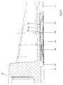
- FIGS. 1 A third embodiment of the device is shown in FIGS.
- the rigid holding plate 14 lies directly on the furniture surface 10, at least in its peripheral region.
- the holding plate 14 On its lower surface, the holding plate 14 has a flat recess 44, which is used for concealed reception of the fastening.
- the anchoring part is designed as an extruded plastic profile 46, which is shown in detail in FIGS. 13 to 15.
- the plastic profile 46 has a low thickness, so that there is a high degree of flexibility.
- the thickness can be, for example, 1 mm to 2 mm.
- the width of the plastic profile 46 is chosen so that there is a sufficient total adhesive area. If necessary, two or more plastic profiles 46 can be arranged in parallel next to each other on the underside of the Holding plate 14 may be arranged.
- the plastic profile 46 has a width of approximately 100 mm, for example.
- the plastic profile 46 is divided into narrow strips by parallel predetermined breaking lines 48 which have a width of approximately 20 mm in the exemplary embodiment mentioned.
- the plastic profile 46 is thinned to a thickness of fractions of a millimeter, so that the individual strips of the plastic profile 46 are held together at the predetermined breaking lines 48, but can be easily separated from one another.
- Continuous profile angles 50 are formed on the top of the plastic profile 46 in the longitudinal direction thereof, which have a free leg parallel to the plane of the plastic profile 46 and which has a width of a few millimeters (for example 3 mm to 4 mm).
- the free leg is a clear distance from the surface of the plastic profile 46, which corresponds to its material thickness.
- the clear distance and the material thickness of the free leg of the profile angle 50 correspond, for example, to the material thickness of the plastic profile 46 from 1 mm to 2 mm.
- a profile angle 50 is formed on each strip of the plastic profile 46.
- a plastic profile 46 is glued to the furniture surface 10 by means of an adhesive layer 52 of a releasable adhesive. Another piece of plastic profile 46 of the same length is rotated by 180 ° and glued with a corresponding adhesive layer 52 into the recess 44 on the underside of the holding plate 14.
- the holding plate 14 is now placed on the furniture surface 10 so that the profile angle 50 of the plastic profile 46 glued onto the furniture surface 10 and the profile angle 50 of the glued to the holding plate 14 Plastic profile 46 are mutually offset in parallel.
- the holding plate 14 is displaced transversely to the direction of the plastic profiles 46 (to the left in FIG. 12), so that the profile angles 50 of the two plastic profiles 46 engage behind one another with their free legs, as can be seen from FIG.
- the holding plate 14 is thereby positively attached to the plastic profile 46 of the anchoring part.
- the height of the recess 44 is selected such that the profile angles 50 of the two plastic profiles 46 engage when the holding plate 14 rests with its circumferential area on the furniture surface 10.
- a flat bar 54 is pushed in the longitudinal direction of the plastic profiles into one of the hollow channels, which passes through the lower and the upper plastic profile 46 and one at the bottom and a profile angle 50 formed on the upper plastic profile 46.
- the flat bar 54 has a width which corresponds to the clear distance between these profile angles 50, so that the flat bar 54 prevents mutual displacement of the plastic profile 46 adhered to the furniture surface 10 and to the holding plate 14.
- the flat bar 54 is pulled out.
- the holding plate 14 can then be moved (to the right in FIG. 12) so that the profile angles 50 of the plastic profiles 46 disengage.
- the holding plate 14 is then lifted off.
- the plastic profile 46 glued to the furniture plate 10 can now be pulled off the furniture surface 10.
- the plastic profile 46 peeled off in strips, wherein it is separated along the predetermined breaking line 48.
- the strip-wise removal of the plastic profile 46 facilitates the detachment of the adhesive layer 52, since this only has to be removed within a short dividing line running across the strip of the plastic profile 46.
- the entire adhesive surface of the plastic profile 46 or the entire adhesive surface of a plurality of plastic profiles 46 arranged next to one another acts for the resilient fastening of the holding plate 14 on the furniture surface 10.
- the rigid design of the holding plate 14 only allows simultaneous removal of the adhesive layer 52 over the entire surface of all of them Plastic profiles 46.
Landscapes
- Engineering & Computer Science (AREA)
- General Engineering & Computer Science (AREA)
- Mechanical Engineering (AREA)
- Connection Of Plates (AREA)
- Supports Or Holders For Household Use (AREA)
- Standing Axle, Rod, Or Tube Structures Coupled By Welding, Adhesion, Or Deposition (AREA)
- Tables And Desks Characterized By Structural Shape (AREA)
- Furniture Connections (AREA)
Claims (14)
- Dispositif de fixation d'un plateau porteur rigide (14) sur la surface (10) d'un meuble par une liaison adhésive (52), caractérisé en ce qu'une pièce d'ancrage (16, 46) est fixée sur la surface (10) par une liaison adhésive (52), le plateau porteur (14) et la pièce d'ancrage (16) étant en prise l'un dans l'autre, avec verrouillage séparable réalisé par combinaison de formes perpendiculairement à la surface (10).
- Dispositif selon la revendication 1, caractérisé en ce que la pièce d'ancrage (16, 46) peut plier élastiquement, se déformer ou fléchir.
- Dispositif selon la revendication 1 ou 2, caractérisé en ce que la pièce d'ancrage (16, 46) a la forme d'une plaque, que le plateau porteur (14) peut être posé à plat sur la pièce d'ancrage (16, 46),et que les surfaces en contact du plateau (14) et de la pièce (16, 46) présentent des saillies (18, 50) et des logements (20, 50) en correspondance, engagés les uns dans les autres avec verrouillage par combinaison de formes.
- Dispositif selon la revendication 3, caractérisé en ce que les saillies (18, 50) sont perpendiculaires au plan défini par les surfaces en contact et viennent en prise par derrière avec des contredépouilles (28, 42, 50) des logements (20, 50) pour assurer, par coulissement du plateau (14) par rapport à la pièce d'ancrage (16, 46), le verrouillage par combinaison de formes.
- Dispositif selon la revendication 4, caractérisé en ce que le plateau porteur (14) et la pièce d'ancrage (16, 46) peuvent être, en position de verrouillage, bloqués de manière à ne pas pouvoir coulisser.
- Dispositif selon la revendication 5, caractérisé en ce que le plateau porteur (14) et la pièce d'ancrage (16) présentent, lorsqu'ils sont en position de verrouillage, des perçages alignés (30, 32) dans lesquels on peut engager une broche d'arrêt.
- Dispositif selon une des revendications précédentes, caractérisé en ce que les saillies (18) et/ou les logements du plateau porteur (14) sont moulés sur la face inférieure.
- Dispositif selon une des revendications 1 à 6, caractérisé en ce que les saillies et/ou les logements du plateau porteur (14) sont portés par une pièce (46) qui peut être fixée sur la face inférieure du plateau porteur (14).
- Dispositif selon une des revendications précédentes, caractérisé en ce que la pièce d'ancrage est un profilé (46) en matière plastique extrudée, en forme de plaque plane, portant sur sa face supérieure un ou plusieurs angles de profilé (50), en saillie et continus selon la direction du profilé.
- Dispositif selon les revendications 8 et 9, caractérisé en ce qu'un profilé (46), identique à celui porté par la pièce d'ancrage mais tourné de 180° autour de son axe longitudinal, est fixé sur la face inférieure du plateau porteur (14), les angles de profilé (50) de ces divers profilés (46) étant en prise les uns dans les autres, avec verrouillage par combinaison de formes.
- Dispositif selon la revendication 9, caractérisé en ce que le profilé en matière plastique (46) de la pièce d'ancrage peut être divisé en bandes longitudinales facilement séparables le long des lignes destinées à la rupture (48).
- Dispositif selon une des revendication précédentes, caractérisé en ce que la pièce d'ancrage (16, 46) est constituée de plusieurs pièces élémentaires disposées à plat et côte à côte.
- Dispositif selon une des revendications précédentes, caractérisé en ce que la liaison par collage (52) est assurée par un adhésif ultérieurement détachable.
- Dispositif selon une des revendications précédentes, caractérisé en ce que la pièce d'ancrage (16) peut laisser passer un agent dissolvant de la colle de liaison.
Priority Applications (2)
| Application Number | Priority Date | Filing Date | Title |
|---|---|---|---|
| US08/058,235 US5407157A (en) | 1992-05-19 | 1993-05-10 | Device for fixing a loadable rigid retaining plate to a furniture surface |
| JP11593793A JPH0681820A (ja) | 1992-05-19 | 1993-05-18 | 荷重に耐えられる剛性保持プレートを家具面に固定する装置 |
Applications Claiming Priority (2)
| Application Number | Priority Date | Filing Date | Title |
|---|---|---|---|
| DE4216515A DE4216515C1 (fr) | 1992-05-19 | 1992-05-19 | |
| DE4216515 | 1992-05-19 |
Publications (2)
| Publication Number | Publication Date |
|---|---|
| EP0570620A1 EP0570620A1 (fr) | 1993-11-24 |
| EP0570620B1 true EP0570620B1 (fr) | 1996-07-10 |
Family
ID=6459233
Family Applications (1)
| Application Number | Title | Priority Date | Filing Date |
|---|---|---|---|
| EP92115407A Expired - Lifetime EP0570620B1 (fr) | 1992-05-19 | 1992-09-09 | Dispositif pour la fixation d'un plateau de support rigide à une surface d'un meuble |
Country Status (3)
| Country | Link |
|---|---|
| EP (1) | EP0570620B1 (fr) |
| AT (1) | ATE140131T1 (fr) |
| DE (2) | DE4216515C1 (fr) |
Families Citing this family (4)
| Publication number | Priority date | Publication date | Assignee | Title |
|---|---|---|---|---|
| DE4228348C1 (de) * | 1992-08-26 | 1993-12-09 | Helmut Steinhilber | Lösbare Befestigung einer Halteplatte an einer Möbelfläche |
| DE19511025C1 (de) * | 1995-03-28 | 1996-11-28 | Helmut Steinhilber | An einem Arbeitstisch angeordnete bewegbare Tragplatte |
| FR2772845B1 (fr) * | 1997-12-23 | 2000-01-21 | Roneo | Systeme de fixation d'un montant sur un plateau |
| AT508175B1 (de) * | 2009-05-06 | 2012-09-15 | Baumann Holding 1886 Gmbh | Verbindung und standsäule |
Family Cites Families (2)
| Publication number | Priority date | Publication date | Assignee | Title |
|---|---|---|---|---|
| US4372224A (en) * | 1980-02-07 | 1983-02-08 | Gary J. Knostman | Knockdown furniture construction |
| DE4016945C1 (fr) * | 1990-05-25 | 1991-08-01 | Helmut Hergiswil Ch Steinhilber |
-
1992
- 1992-05-19 DE DE4216515A patent/DE4216515C1/de not_active Expired - Fee Related
- 1992-09-09 EP EP92115407A patent/EP0570620B1/fr not_active Expired - Lifetime
- 1992-09-09 AT AT92115407T patent/ATE140131T1/de not_active IP Right Cessation
- 1992-09-09 DE DE59206747T patent/DE59206747D1/de not_active Expired - Fee Related
Also Published As
| Publication number | Publication date |
|---|---|
| ATE140131T1 (de) | 1996-07-15 |
| DE59206747D1 (de) | 1996-08-14 |
| EP0570620A1 (fr) | 1993-11-24 |
| DE4216515C1 (fr) | 1993-06-03 |
Similar Documents
| Publication | Publication Date | Title |
|---|---|---|
| WO1994001019A1 (fr) | Kit de tiroir | |
| DE1750713B2 (de) | Verbindung von Holzbauteilen einer Baukonstruktion mit zwei Krallenplatten | |
| EP0592847A2 (fr) | Dispositif pour fixer une plaque rigide à une embase de fixation | |
| EP0728507A2 (fr) | Jeu de construction | |
| DE3729903C2 (fr) | ||
| LV11356B (en) | Form for shaping of building parts | |
| EP0570620B1 (fr) | Dispositif pour la fixation d'un plateau de support rigide à une surface d'un meuble | |
| EP0913139A1 (fr) | Système de table d'opération modulaire | |
| EP0030290A2 (fr) | Tiroir | |
| EP0171813B1 (fr) | Ferrure coulissante | |
| EP0096898A1 (fr) | Tiroir pour armoires | |
| DE4211072C2 (de) | Anordnung zur Verbindung zweier Bauteile | |
| EP1580341B1 (fr) | Élément de liaison pour une construction de profilés et construction de profilés | |
| EP0847466B1 (fr) | Cloison mobile | |
| DE2706277C3 (de) | Siebboden | |
| EP0185201B1 (fr) | Tiroir en matière plastique | |
| DE2716399C2 (fr) | ||
| EP1728452A1 (fr) | Elément de liaison pour construction des meubles | |
| DE19527692C2 (de) | Vorrichtung zur Aufnahme eines Tafelelements | |
| DE2100879C3 (de) | Kassettenschild | |
| DE19620709C5 (de) | Möbelfußsystem | |
| WO2003030322A1 (fr) | Socle pour un coffret de distribution | |
| EP3735150B1 (fr) | Ensemble formé d'une nervure d'appui pour fond de tiroir et d'un dispositif de retenue | |
| EP3552524B1 (fr) | Distributeur pour d'avancement de la marchandises | |
| WO2023020772A1 (fr) | Système de fixation |
Legal Events
| Date | Code | Title | Description |
|---|---|---|---|
| PUAI | Public reference made under article 153(3) epc to a published international application that has entered the european phase |
Free format text: ORIGINAL CODE: 0009012 |
|
| AK | Designated contracting states |
Kind code of ref document: A1 Designated state(s): AT BE CH DE ES FR GB IT LI NL SE |
|
| 17P | Request for examination filed |
Effective date: 19940324 |
|
| GRAH | Despatch of communication of intention to grant a patent |
Free format text: ORIGINAL CODE: EPIDOS IGRA |
|
| 17Q | First examination report despatched |
Effective date: 19951127 |
|
| GRAH | Despatch of communication of intention to grant a patent |
Free format text: ORIGINAL CODE: EPIDOS IGRA |
|
| GRAA | (expected) grant |
Free format text: ORIGINAL CODE: 0009210 |
|
| AK | Designated contracting states |
Kind code of ref document: B1 Designated state(s): AT BE CH DE ES FR GB IT LI NL SE |
|
| PG25 | Lapsed in a contracting state [announced via postgrant information from national office to epo] |
Ref country code: NL Free format text: LAPSE BECAUSE OF FAILURE TO SUBMIT A TRANSLATION OF THE DESCRIPTION OR TO PAY THE FEE WITHIN THE PRESCRIBED TIME-LIMIT Effective date: 19960710 Ref country code: ES Free format text: THE PATENT HAS BEEN ANNULLED BY A DECISION OF A NATIONAL AUTHORITY Effective date: 19960710 |
|
| REF | Corresponds to: |
Ref document number: 140131 Country of ref document: AT Date of ref document: 19960715 Kind code of ref document: T |
|
| ITF | It: translation for a ep patent filed |
Owner name: FIAMMENGHI - DOMENIGHETTI |
|
| REG | Reference to a national code |
Ref country code: CH Ref legal event code: NV Representative=s name: DIPL.-ING. ETH H. R. WERFFELI PATENTANWALT |
|
| ET | Fr: translation filed | ||
| REF | Corresponds to: |
Ref document number: 59206747 Country of ref document: DE Date of ref document: 19960814 |
|
| GBT | Gb: translation of ep patent filed (gb section 77(6)(a)/1977) |
Effective date: 19960820 |
|
| PG25 | Lapsed in a contracting state [announced via postgrant information from national office to epo] |
Ref country code: BE Effective date: 19960930 |
|
| NLV1 | Nl: lapsed or annulled due to failure to fulfill the requirements of art. 29p and 29m of the patents act | ||
| PLBE | No opposition filed within time limit |
Free format text: ORIGINAL CODE: 0009261 |
|
| STAA | Information on the status of an ep patent application or granted ep patent |
Free format text: STATUS: NO OPPOSITION FILED WITHIN TIME LIMIT |
|
| 26N | No opposition filed | ||
| PGFP | Annual fee paid to national office [announced via postgrant information from national office to epo] |
Ref country code: SE Payment date: 19980929 Year of fee payment: 7 |
|
| PGFP | Annual fee paid to national office [announced via postgrant information from national office to epo] |
Ref country code: FR Payment date: 19990917 Year of fee payment: 8 |
|
| PGFP | Annual fee paid to national office [announced via postgrant information from national office to epo] |
Ref country code: GB Payment date: 19990922 Year of fee payment: 8 |
|
| PG25 | Lapsed in a contracting state [announced via postgrant information from national office to epo] |
Ref country code: SE Free format text: THE PATENT HAS BEEN ANNULLED BY A DECISION OF A NATIONAL AUTHORITY Effective date: 19990929 |
|
| EUG | Se: european patent has lapsed |
Ref document number: 92115407.6 |
|
| PG25 | Lapsed in a contracting state [announced via postgrant information from national office to epo] |
Ref country code: GB Free format text: LAPSE BECAUSE OF NON-PAYMENT OF DUE FEES Effective date: 20000909 |
|
| PGFP | Annual fee paid to national office [announced via postgrant information from national office to epo] |
Ref country code: AT Payment date: 20000922 Year of fee payment: 9 |
|
| GBPC | Gb: european patent ceased through non-payment of renewal fee |
Effective date: 20000909 |
|
| PG25 | Lapsed in a contracting state [announced via postgrant information from national office to epo] |
Ref country code: FR Free format text: LAPSE BECAUSE OF NON-PAYMENT OF DUE FEES Effective date: 20010531 |
|
| REG | Reference to a national code |
Ref country code: FR Ref legal event code: ST |
|
| PG25 | Lapsed in a contracting state [announced via postgrant information from national office to epo] |
Ref country code: AT Free format text: LAPSE BECAUSE OF NON-PAYMENT OF DUE FEES Effective date: 20010909 |
|
| PGFP | Annual fee paid to national office [announced via postgrant information from national office to epo] |
Ref country code: CH Payment date: 20030923 Year of fee payment: 12 |
|
| PGFP | Annual fee paid to national office [announced via postgrant information from national office to epo] |
Ref country code: DE Payment date: 20031027 Year of fee payment: 12 |
|
| PG25 | Lapsed in a contracting state [announced via postgrant information from national office to epo] |
Ref country code: LI Free format text: LAPSE BECAUSE OF NON-PAYMENT OF DUE FEES Effective date: 20040930 Ref country code: CH Free format text: LAPSE BECAUSE OF NON-PAYMENT OF DUE FEES Effective date: 20040930 |
|
| PG25 | Lapsed in a contracting state [announced via postgrant information from national office to epo] |
Ref country code: DE Free format text: LAPSE BECAUSE OF NON-PAYMENT OF DUE FEES Effective date: 20050401 |
|
| REG | Reference to a national code |
Ref country code: CH Ref legal event code: PL |
|
| PG25 | Lapsed in a contracting state [announced via postgrant information from national office to epo] |
Ref country code: IT Free format text: LAPSE BECAUSE OF NON-PAYMENT OF DUE FEES Effective date: 20050909 |