EP0570620B1 - Device for attaching a rigid support to a furniture surface - Google Patents
Device for attaching a rigid support to a furniture surface Download PDFInfo
- Publication number
- EP0570620B1 EP0570620B1 EP92115407A EP92115407A EP0570620B1 EP 0570620 B1 EP0570620 B1 EP 0570620B1 EP 92115407 A EP92115407 A EP 92115407A EP 92115407 A EP92115407 A EP 92115407A EP 0570620 B1 EP0570620 B1 EP 0570620B1
- Authority
- EP
- European Patent Office
- Prior art keywords
- anchoring part
- plate
- anchoring
- holding plate
- retention plate
- Prior art date
- Legal status (The legal status is an assumption and is not a legal conclusion. Google has not performed a legal analysis and makes no representation as to the accuracy of the status listed.)
- Expired - Lifetime
Links
- 238000004873 anchoring Methods 0.000 claims abstract description 93
- 239000004033 plastic Substances 0.000 claims description 40
- 239000000853 adhesive Substances 0.000 claims description 33
- 230000001070 adhesive effect Effects 0.000 claims description 33
- 239000002904 solvent Substances 0.000 claims description 6
- 238000006073 displacement reaction Methods 0.000 claims description 3
- 230000014759 maintenance of location Effects 0.000 claims 12
- 238000010276 construction Methods 0.000 claims 1
- 238000003780 insertion Methods 0.000 description 10
- 230000037431 insertion Effects 0.000 description 10
- 239000000463 material Substances 0.000 description 5
- 239000012790 adhesive layer Substances 0.000 description 4
- 238000004519 manufacturing process Methods 0.000 description 2
- 238000000926 separation method Methods 0.000 description 2
- 239000002313 adhesive film Substances 0.000 description 1
- 238000005452 bending Methods 0.000 description 1
- 230000000694 effects Effects 0.000 description 1
- 238000005516 engineering process Methods 0.000 description 1
- 239000003000 extruded plastic Substances 0.000 description 1
- 239000003292 glue Substances 0.000 description 1
- 239000002184 metal Substances 0.000 description 1
- 230000002093 peripheral effect Effects 0.000 description 1
- 239000011148 porous material Substances 0.000 description 1
- 239000004753 textile Substances 0.000 description 1
Images


Classifications
-
- A—HUMAN NECESSITIES
- A47—FURNITURE; DOMESTIC ARTICLES OR APPLIANCES; COFFEE MILLS; SPICE MILLS; SUCTION CLEANERS IN GENERAL
- A47B—TABLES; DESKS; OFFICE FURNITURE; CABINETS; DRAWERS; GENERAL DETAILS OF FURNITURE
- A47B21/00—Tables or desks for office equipment, e.g. typewriters, keyboards
- A47B21/03—Tables or desks for office equipment, e.g. typewriters, keyboards with substantially horizontally extensible or adjustable parts other than drawers, e.g. leaves
-
- F—MECHANICAL ENGINEERING; LIGHTING; HEATING; WEAPONS; BLASTING
- F16—ENGINEERING ELEMENTS AND UNITS; GENERAL MEASURES FOR PRODUCING AND MAINTAINING EFFECTIVE FUNCTIONING OF MACHINES OR INSTALLATIONS; THERMAL INSULATION IN GENERAL
- F16B—DEVICES FOR FASTENING OR SECURING CONSTRUCTIONAL ELEMENTS OR MACHINE PARTS TOGETHER, e.g. NAILS, BOLTS, CIRCLIPS, CLAMPS, CLIPS OR WEDGES; JOINTS OR JOINTING
- F16B12/00—Jointing of furniture or the like, e.g. hidden from exterior
- F16B12/10—Jointing of furniture or the like, e.g. hidden from exterior using pegs, bolts, tenons, clamps, clips, or the like
- F16B12/12—Jointing of furniture or the like, e.g. hidden from exterior using pegs, bolts, tenons, clamps, clips, or the like for non-metal furniture parts, e.g. made of wood, of plastics
-
- F—MECHANICAL ENGINEERING; LIGHTING; HEATING; WEAPONS; BLASTING
- F16—ENGINEERING ELEMENTS AND UNITS; GENERAL MEASURES FOR PRODUCING AND MAINTAINING EFFECTIVE FUNCTIONING OF MACHINES OR INSTALLATIONS; THERMAL INSULATION IN GENERAL
- F16B—DEVICES FOR FASTENING OR SECURING CONSTRUCTIONAL ELEMENTS OR MACHINE PARTS TOGETHER, e.g. NAILS, BOLTS, CIRCLIPS, CLAMPS, CLIPS OR WEDGES; JOINTS OR JOINTING
- F16B12/00—Jointing of furniture or the like, e.g. hidden from exterior
- F16B12/40—Joints for furniture tubing
- F16B12/42—Joints for furniture tubing connecting furniture tubing to non-tubular parts
-
- A—HUMAN NECESSITIES
- A47—FURNITURE; DOMESTIC ARTICLES OR APPLIANCES; COFFEE MILLS; SPICE MILLS; SUCTION CLEANERS IN GENERAL
- A47B—TABLES; DESKS; OFFICE FURNITURE; CABINETS; DRAWERS; GENERAL DETAILS OF FURNITURE
- A47B37/00—Tables adapted for other particular purposes
- A47B2037/005—Tables specially adapted for laboratories
-
- A—HUMAN NECESSITIES
- A47—FURNITURE; DOMESTIC ARTICLES OR APPLIANCES; COFFEE MILLS; SPICE MILLS; SUCTION CLEANERS IN GENERAL
- A47B—TABLES; DESKS; OFFICE FURNITURE; CABINETS; DRAWERS; GENERAL DETAILS OF FURNITURE
- A47B2200/00—General construction of tables or desks
- A47B2200/0084—Accessories for tables or desks
- A47B2200/0085—Supplementary support fixed on the edge of a desk or table
Definitions
- the invention relates to a device for fastening a resilient, rigid holding plate to a furniture surface according to the preamble of patent claim 1.
- a holding plate is placed flat on a table top and fastened to it by means of a textile adhesive fastener, part of which is glued to the table top.
- the holding plate carries a vertical support column which is suitable for accommodating different functional elements, for example the plate of a standing desk, a display support, a telephone arm, a lamp or the like. This means that any desks and work tables can be retrofitted using the vertical support column.
- the attachment of the holding plate on the table top has the advantage over conventional clamping devices that the attachment is independent of the shape of the table top and the furniture.
- this type of attachment can be used with any thickness of the table top, with any edge shape of the table top and also with the table top not protruding beyond the body.
- the holding plate can be removed from the furniture surface without damaging it.
- the rigid holding plate is first cut off in the area of the adhesive fastener. Then the part of the adhesive fastener glued onto the furniture surface can be separated from the furniture surface. Since this part is flexible, it can be carefully removed from the furniture surface without damaging it. This would be difficult if the rigid holding plate were glued directly onto the furniture surface, since the adhesive connection would have to be torn off over the entire adhesive surface at the same time.
- the invention is based on the problem of creating a device for fastening a rigid holding plate to a furniture surface, which combines high resilience with simple releasability of the fastening.
- the holding plate is fastened to the furniture surface, for example on the table top of a work or desk.
- the holding plate does not protrude beyond the edge of the furniture surface, so that attachment to any furniture surface, regardless of the shape of the piece of furniture, and in any area of the furniture surface is possible. All advantages of the known fastening are thus fulfilled in the same way.
- An anchoring part is glued onto the furniture surface, for which purpose a releasable adhesive is preferably used.
- the holding plate is positively attached to this anchoring part.
- the interlocking locking of the rigid holding plate to the anchoring part enables the holding plate to be easily attached to the anchoring part and also an easy release of the holding plate from the anchoring part.
- the anchoring part itself which is preferably in the form of an anchoring plate, can be resiliently flexible, deformable or flexible, so that it can be detached from the furniture surface relatively easily if required, starting from an edge or a corner is successively separated and peeled off. If necessary, a solvent can also be applied.
- the anchoring part As soon as the rigid cold plate is connected to the anchoring part, the anchoring part is completely stiffened by the holding plate, so that it is no longer possible to bend or deform the anchoring part.
- the adhesive connection between the anchoring part and the furniture surface can therefore no longer be detached progressively along a dividing line when the holding plate is attached, but a separation of the adhesive connection would only be possible over the entire surface of the adhesive connection at the same time.
- the adhesive attachment of the holding plate can absorb a high load, particularly due to tilting moments.
- the positive connection of the holding plate with the anchoring part enables the holding plate to be easily removed if the holding plate and the functional elements attached to it are to be removed for a short time or if a holding plate with one functional element is to be exchanged for a holding plate with another functional element. If the device is to be completely removed, then after the positive connection has been disconnected and after the rigid holding plate has been removed, the anchoring part, which is then freely accessible and is no longer stiffened by the rigid holding plate, is detached from the furniture surface, the anchoring part being carefully peeled off and along a moving dividing line can be separated. If necessary, a solvent for the adhesive used can be applied through the anchoring part onto the entire adhesive surface or along the respective dividing line between the anchoring part and the furniture surface.
- the positive connection and locking of the holding plate and anchoring part can be realized in many ways.
- the anchoring part is preferably designed as an anchoring plate on which the holding plate is placed flat. Protrusions and receptacles of the surfaces of the anchoring plate and the holding plate which sit on one another engage in a form-fitting manner in this case.
- the holding plate can thus be placed on the anchoring plate glued to the furniture surface and locked by sliding.
- the anchoring part is completely covered by the holding plate, so that the fastening measures are invisible and an elegant appearance is guaranteed.
- a large-area anchoring plate is provided.
- the anchoring plate is divided by predetermined breaking lines. As long as the anchoring plate is stiffened by the rigid holding plate, these predetermined breaking lines are ineffective and the entire surface of the anchoring plate acts as a continuous surface of the adhesive connection. If the holding plate is removed, the anchoring plate can be detached separately from the furniture surface in the individual areas divided by the predetermined breaking lines, so that there is in each case a smaller adhesive surface and thus an easier detachment.
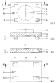
- a vertical support column 12 is to be attached to a furniture surface 10, for example the worktop of a desk.
- the support column 12 serves to carry functional elements, e.g. a standing desk top, a screen arm, a telephone arm, a table lamp or the like.
- a horizontal rigid holding plate 14 is attached at the lower end of the support column 12.
- the support column 12 and the holding plate 14 consist of a suitable material, for example cast metal or plastic.
- An anchoring part in the form of an anchoring plate 16 is glued onto the furniture surface 10.
- An adhesive applied on one side to the underside of the anchoring plate 16 or a double-sided adhesive film can be used to glue the anchoring plate 16 on.
- the holding plate 14 and the anchoring plate 16 have the same area, so that when the holding plate 14 is placed on the anchoring plate 16, these two plates visually connect to form a uniform plate.
- the surface dimensions of the holding plate 14 and the anchoring plate 16 are chosen such that there is sufficient support for the support column 12, in particular against tilting moments.
- the holding plate 14 and the anchoring plate 16 can accordingly be triangular, rectangular and in particular have square shapes, as shown in the drawing.
- the holding plate 14 and the anchoring plate 16 can also be formed from two or more rails arranged on the furniture surface 10 and arranged at an angle, preferably a right angle .
- the anchoring plate 16 is preferably made of an elastic plastic material, so that a deflection of the anchoring plate 16 is possible. This makes it easier to detach the anchoring plate 16 from the furniture surface 10.
- the anchoring plate 16 can be lifted off the furniture surface 10 at one of its corners and then progressively peeled off the furniture surface 10 with bending. The bonding of the anchoring plate 16 to the furniture surface 10 is progressively separated in each case only along one line. This means that less effort is required to detach it and the furniture surface 10 is protected.
- a soluble adhesive is preferably used to adhere the anchor plate 16. If the anchoring plate 16 is to be detached, a solvent can first be applied to facilitate detachment. In order to bring the solvent to the adhesive surface, the anchoring plate 16 can optionally consist of a porous material or have openings through which the solvent can reach the adhesive surface.
- the holding plate 14 is positively attached to the anchoring plate 16.
- the holding plate 14 has on its underside projections 18 which engage positively in receptacles 20 of the anchoring plate 16.
- the number of projections 18 and the receptacles 20 depends on the Size and shape of the holding plate 14 and the anchoring plate 16 from and also from the tilting load to be absorbed by the support column 12.
- the holding plate 14 and the anchoring plate 16 are of rectangular design and a projection 18 and a corresponding receptacle 20 are assigned to each corner.
- the projections 18 of the holding plate 14 each consist of a rectangular block 22 projecting perpendicularly from the underside of the holding plate 14, on the lower end of which a nose 24 projects on one side parallel to the plane of the holding plate.
- the lugs 24 of all the projections 18 point in the same direction.
- the receptacles 20 of the anchoring plate 16 corresponding to the protrusions 18 have an insertion opening 26 which passes through the anchoring plate 16 and whose cross section corresponds to the cross section of the surface of block 22 and nose 24 of the protrusions 18.
- an undercut 28 for the lugs 24 of the projections 18 adjoins the insertion openings 26.
- the undercuts 28 are open on the underside of the anchoring plate 16, so that the anchoring plate 16 with the undercuts 28 is easy to manufacture in terms of production technology.
- the holding plate 14 To fasten the holding plate 14 to the anchoring plate 16, the holding plate 14 is placed on the anchoring plate 16 from above, the projections 18 being inserted into the insertion openings 26 of the receptacles 20. As soon as the holding plate 14 lies flat on the anchoring plate 16, the holding plate 14 becomes on the anchoring plate 16 shifted (to the right in the illustration of FIGS. 2 to 5), so that the lugs 24 of the projections 18 reach the undercuts 28 of the receptacles 20. As a result, the holding plate 14 is locked to the anchoring plate 16 and can no longer be lifted off the anchoring plate 16. In this locked position, the holding plate 14 comes to coincide with the anchoring plate 16, as is shown in FIG. 1.
- the holding plate 14 In order to lock the holding plate 14 in this locking position, the holding plate 14 has a vertically continuous bore 30 and the anchoring plate 16 has a vertical bore 32.
- the holes 30 and 32 are arranged so that they are axially aligned in the locking position of the holding plate 14 and the anchoring plate 16.
- a locking pin inserted into the bores 30 and 32 locks the holding plate 14 in the locking position against displacement on the anchoring plate 16. By pulling out the locking pin, the locking can be released again, so that the holding plate 14 can be moved again and lifted off the anchoring plate 16 .
- FIGS. 6 to 11 show a second embodiment of the projections 18 and the receptacles 20.
- the projections 18 consist of a web 34 projecting perpendicularly on the underside of the holding plate 14 with a flange 36 formed on its lower end, which projects on both sides parallel to the plane of the holding plate 14.
- the receptacles 20 have an insertion opening 38 through the anchoring plate 16, the cross section of which corresponds to the cross section of the flange 36.
- An insertion slot 40 adjoins the insertion opening 38, the width of which corresponds to the width of the web 34 corresponds.
- the insertion slot 40 widens on the underside of the anchoring plate 16 on both sides to form an undercut 42 for the flange 36.
- the length of the insertion slot corresponds to the length of the web 34.
- the holding plate 14 is placed on the anchoring plate 16 for fastening, the projections 18 are inserted into the insertion openings 38 until the holding plate 14 is seated on the anchoring plate 16. Then the holding plate 14 is displaced on the anchoring plate 16, the webs 34 of the projections 18 entering the insertion slots 40 and the flanges 36 each coming into the undercuts 42. As a result, the holding plate 14 is positively locked on the anchoring plate 16. In this embodiment, too, a locking pin is used to lock the holding plate 14 in the locking position.
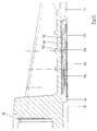
- FIGS. 1 A third embodiment of the device is shown in FIGS.
- the rigid holding plate 14 lies directly on the furniture surface 10, at least in its peripheral region.
- the holding plate 14 On its lower surface, the holding plate 14 has a flat recess 44, which is used for concealed reception of the fastening.
- the anchoring part is designed as an extruded plastic profile 46, which is shown in detail in FIGS. 13 to 15.
- the plastic profile 46 has a low thickness, so that there is a high degree of flexibility.
- the thickness can be, for example, 1 mm to 2 mm.
- the width of the plastic profile 46 is chosen so that there is a sufficient total adhesive area. If necessary, two or more plastic profiles 46 can be arranged in parallel next to each other on the underside of the Holding plate 14 may be arranged.
- the plastic profile 46 has a width of approximately 100 mm, for example.
- the plastic profile 46 is divided into narrow strips by parallel predetermined breaking lines 48 which have a width of approximately 20 mm in the exemplary embodiment mentioned.
- the plastic profile 46 is thinned to a thickness of fractions of a millimeter, so that the individual strips of the plastic profile 46 are held together at the predetermined breaking lines 48, but can be easily separated from one another.
- Continuous profile angles 50 are formed on the top of the plastic profile 46 in the longitudinal direction thereof, which have a free leg parallel to the plane of the plastic profile 46 and which has a width of a few millimeters (for example 3 mm to 4 mm).
- the free leg is a clear distance from the surface of the plastic profile 46, which corresponds to its material thickness.
- the clear distance and the material thickness of the free leg of the profile angle 50 correspond, for example, to the material thickness of the plastic profile 46 from 1 mm to 2 mm.
- a profile angle 50 is formed on each strip of the plastic profile 46.
- a plastic profile 46 is glued to the furniture surface 10 by means of an adhesive layer 52 of a releasable adhesive. Another piece of plastic profile 46 of the same length is rotated by 180 ° and glued with a corresponding adhesive layer 52 into the recess 44 on the underside of the holding plate 14.
- the holding plate 14 is now placed on the furniture surface 10 so that the profile angle 50 of the plastic profile 46 glued onto the furniture surface 10 and the profile angle 50 of the glued to the holding plate 14 Plastic profile 46 are mutually offset in parallel.
- the holding plate 14 is displaced transversely to the direction of the plastic profiles 46 (to the left in FIG. 12), so that the profile angles 50 of the two plastic profiles 46 engage behind one another with their free legs, as can be seen from FIG.
- the holding plate 14 is thereby positively attached to the plastic profile 46 of the anchoring part.
- the height of the recess 44 is selected such that the profile angles 50 of the two plastic profiles 46 engage when the holding plate 14 rests with its circumferential area on the furniture surface 10.
- a flat bar 54 is pushed in the longitudinal direction of the plastic profiles into one of the hollow channels, which passes through the lower and the upper plastic profile 46 and one at the bottom and a profile angle 50 formed on the upper plastic profile 46.
- the flat bar 54 has a width which corresponds to the clear distance between these profile angles 50, so that the flat bar 54 prevents mutual displacement of the plastic profile 46 adhered to the furniture surface 10 and to the holding plate 14.
- the flat bar 54 is pulled out.
- the holding plate 14 can then be moved (to the right in FIG. 12) so that the profile angles 50 of the plastic profiles 46 disengage.
- the holding plate 14 is then lifted off.
- the plastic profile 46 glued to the furniture plate 10 can now be pulled off the furniture surface 10.
- the plastic profile 46 peeled off in strips, wherein it is separated along the predetermined breaking line 48.
- the strip-wise removal of the plastic profile 46 facilitates the detachment of the adhesive layer 52, since this only has to be removed within a short dividing line running across the strip of the plastic profile 46.
- the entire adhesive surface of the plastic profile 46 or the entire adhesive surface of a plurality of plastic profiles 46 arranged next to one another acts for the resilient fastening of the holding plate 14 on the furniture surface 10.
- the rigid design of the holding plate 14 only allows simultaneous removal of the adhesive layer 52 over the entire surface of all of them Plastic profiles 46.
Abstract
Description
Die Erfindung betrifft eine Vorrichtung zur Befestigung einer belastbaren starren Halteplatte an einer Möbelfläche gemäß dem Oberbegriff des Patentanspruchs 1.The invention relates to a device for fastening a resilient, rigid holding plate to a furniture surface according to the preamble of patent claim 1.
Bei einer aus EP 0 457 957 A1, Ausführungsbeispiel der Figur 8, bekannten Vorrichtung dieser Gattung wird eine Halteplatte flach auf eine Tischplatte aufgesetzt und an dieser mittels eines textilen Haftverschlusses befestigt, dessen einer Teil auf die Tischplatte geklebt wird. Die Halteplatte trägt eine vertikale Stützsäule, die sich zur Aufnahme unterschiedlicher Funktionselemente, beispielsweise der Platte eines Stehpultes, eines Bildschirmträgers, eines Telefonarmes, einer Leuchte oder dergleichen eignet. Dadurch ist ein Nachrüsten beliebiger Schreib- und Arbeitstische mittels der vertikalen Stützsäule möglich.In a device of this type known from EP 0 457 957 A1, embodiment of FIG. 8, a holding plate is placed flat on a table top and fastened to it by means of a textile adhesive fastener, part of which is glued to the table top. The holding plate carries a vertical support column which is suitable for accommodating different functional elements, for example the plate of a standing desk, a display support, a telephone arm, a lamp or the like. This means that any desks and work tables can be retrofitted using the vertical support column.
Die Befestigung der Halteplatte auf der Tischplatte hat gegenüber herkömmlichen Klemmvorrichtungen den Vorteil, daß die Befestigung von der Form der Tischplatte und des Möbels unabhängig ist. Insbesondere kann diese Art der Befestigung bei jeder Stärke der Tischplatte, bei jeder Kantenform der Tischplatte und auch bei nicht über den Korpus überragender Tischplatte verwendet werden.The attachment of the holding plate on the table top has the advantage over conventional clamping devices that the attachment is independent of the shape of the table top and the furniture. In particular, this type of attachment can be used with any thickness of the table top, with any edge shape of the table top and also with the table top not protruding beyond the body.
Die Halteplatte kann von der Möbeloberfläche wieder entfernt werden, ohne daß diese beschädigt wird. Hierzu wird zunächst die starre Halteplatte im Bereich des Haftverschlusses abgetrennt. Dann kann der auf die Möbelfläche aufgeklebte Teil des Haftverschlusses von der Möbelfläche abgetrennt werden. Da dieser Teil flexibel ist, kann er behutsam von der Möbelfläche abgelöst werden, ohne diese zu beschädigen. Dies wäre bei einem unmittelbaren Aufkleben der starren Halteplatte auf die Möbelfläche schwierig, da die Klebverbindung gleichzeitig über die gesamte Klebefläche abgerissen werden müßte.The holding plate can be removed from the furniture surface without damaging it. For this purpose, the rigid holding plate is first cut off in the area of the adhesive fastener. Then the part of the adhesive fastener glued onto the furniture surface can be separated from the furniture surface. Since this part is flexible, it can be carefully removed from the furniture surface without damaging it. This would be difficult if the rigid holding plate were glued directly onto the furniture surface, since the adhesive connection would have to be torn off over the entire adhesive surface at the same time.
Das Trennen des Haftverschlusses kann jedoch insbesondere bei einem für höhere Belastungen geeigneten großflächigen Haftverschluß Schwierigkeiten bereiten, da wegen der starren Ausbildung der Halteplatte auch der Haftverschluß im wesentlichen über seine gesamte Fläche gleichzeitig getrennt werden muß. Diese Trennung ist zwar möglich, da der Haftverschluß senkrecht zu seiner Ebene eine minimale elastische Nachgiebigkeit aufweist, so daß die Halteplatte von einem Ende beginnend fortschreitend, beispielsweise mittels eines Hebelwerkzeuges, abgehoben werden kann. Diese geringe elastische Nachgiebigkeit des Haftverschlusses kann aber auch zu einen unerwünschten allmählichen Lockern der Haftverbindung führen, insbesondere wenn auf die Halteplatte über eine lange Zeit ein sehr starkes Kippmoment einwirkt.However, separating the adhesive fastener can be difficult, in particular in the case of a large-area adhesive fastener suitable for higher loads, since, because of the rigid design of the holding plate, the adhesive fastener also has to be separated essentially over its entire surface at the same time. This separation is possible because the adhesive closure has a minimal elastic flexibility perpendicular to its plane, so that the holding plate can be lifted off progressively from one end, for example by means of a lever tool. This low elastic compliance of the adhesive fastener can also lead to an undesirable gradual loosening of the adhesive connection, especially when applied to the holding plate a very strong tilting moment acts over a long time.
Der Erfindung liegt das Problem zugrunde, eine Vorrichtung zur Befestigung einer starren Halteplatte an einer Möbelfläche zu schaffen, die eine hohe Belastbarkeit mit einer einfachen Lösbarkeit der Befestigung vereinigt.The invention is based on the problem of creating a device for fastening a rigid holding plate to a furniture surface, which combines high resilience with simple releasability of the fastening.
Dieses Problem wird erfindungsgemäß gelöst durch eine Vorrichtung mit den Merkmalen des Patentanspruchs 1.According to the invention, this problem is solved by a device having the features of patent claim 1.
Vorteilhafte Ausführungen der Erfindung sind in den Unteransprüchen angegeben.Advantageous embodiments of the invention are specified in the subclaims.
Bei der erfindungsgemäßen Vorrichtung wird die Halteplatte an der Möbelfläche, beispielsweise auf der Tischplatte eines Arbeits- oder Schreibtisches befestigt. Die Halteplatte ragt dabei nicht über den Rand der Möbelfläche hinaus, so daß eine Befestigung an jeder beliebigen Möbelfläche, unabhängig von der Form des Möbelstückes, und in jedem beliebigen Bereich der Möbelfläche möglich ist. Alle Vorteile der bekannten Befestigung sind somit in gleicher Weise erfüllt.In the device according to the invention, the holding plate is fastened to the furniture surface, for example on the table top of a work or desk. The holding plate does not protrude beyond the edge of the furniture surface, so that attachment to any furniture surface, regardless of the shape of the piece of furniture, and in any area of the furniture surface is possible. All advantages of the known fastening are thus fulfilled in the same way.
Auf die Möbelfläche wird ein Verankerungsteil aufgeklebt, wozu vorzugsweise ein lösbarer Klebstoff verwendet wird. Die Halteplatte wird an diesem Verankerungsteil formschlüssig befestigt. Die formschlüssige Verriegelung der starren Halteplatte mit dem Verankerungsteil ermöglicht ein einfaches Befestigen der Halteplatte an dem Verankerungsteil und ebenso ein leichtes Lösen der Halteplatte von dem Verankerungsteil. Das Verankerungsteil selbst, welches vorzugsweise in Form einer Verankerungsplatte ausgebildet ist, kann elastisch biegsam, verformbar oder flexibel sein, so daß es bei Bedarf relativ leicht von der Möbelfläche abgelöst werden kann, indem es von einem Rand oder einer Ecke beginnend sukzessive abgetrennt und abgeschält wird. Gegebenenfalls kann hierzu auch ein Lösungsmittel appliziert werden.An anchoring part is glued onto the furniture surface, for which purpose a releasable adhesive is preferably used. The holding plate is positively attached to this anchoring part. The interlocking locking of the rigid holding plate to the anchoring part enables the holding plate to be easily attached to the anchoring part and also an easy release of the holding plate from the anchoring part. The anchoring part itself, which is preferably in the form of an anchoring plate, can be resiliently flexible, deformable or flexible, so that it can be detached from the furniture surface relatively easily if required, starting from an edge or a corner is successively separated and peeled off. If necessary, a solvent can also be applied.
Sobald die starre Kalteplatte mit dem Verankerungsteil verbunden ist, wird das Verankerungsteil durch die Halteplatte vollständig versteift, so daß eine Verbiegung oder Verformung des Verankerungsteils nicht mehr möglich ist. Die Klebeverbindung zwischen Verankerungsteil und Möbelfläche kann daher bei aufgesetzter Halteplatte nicht mehr fortschreitend entlang einer Trennlinie abgelöst werden, sondern eine Trennung der Klebeverbindung wäre nur noch über die gesamte Fläche der Klebeverbindung gleichzeitig möglich. Dadurch kann die Klebebefestigung der Halteplatte eine hohe Belastung insbesondere auch durch Kippmomente aufnehmen.As soon as the rigid cold plate is connected to the anchoring part, the anchoring part is completely stiffened by the holding plate, so that it is no longer possible to bend or deform the anchoring part. The adhesive connection between the anchoring part and the furniture surface can therefore no longer be detached progressively along a dividing line when the holding plate is attached, but a separation of the adhesive connection would only be possible over the entire surface of the adhesive connection at the same time. As a result, the adhesive attachment of the holding plate can absorb a high load, particularly due to tilting moments.
Die formschlüssige Verbindung der Halteplatte mit dem Verankerungsteil ermöglicht ein einfaches Wegnehmen der Halteplatte, wenn die Halteplatte und an dieser angebrachte Funktionselemente kurzzeitig entfernt werden sollen oder wenn eine Halteplatte mit einem Funktionselement gegen eine Halteplatte mit einem anderen Funktionselement ausgetauscht werden soll. Soll die Vorrichtung vollständig entfernt werden, so wird nach dem Trennen der formschlüssigen Verbindung und nach dem Wegnehmen der starren Halteplatte das dann frei zugängliche und nicht mehr durch die starre Halteplatte versteifte Verankerungsteil von der Möbelfläche abgelöst, wobei das Verankerungsteil behutsam abgeschält und entlang einer wandernden Trennungslinie abgetrennt werden kann. Gegebenenfalls kann ein Lösungsmittel für den verwendeten Klebstoff durch das Verankerungsteil hindurch auf die gesamte Klebefläche oder entlang der jeweiligen Trennlinie zwischen Verankerungsteil und Möbelfläche appliziert werden.The positive connection of the holding plate with the anchoring part enables the holding plate to be easily removed if the holding plate and the functional elements attached to it are to be removed for a short time or if a holding plate with one functional element is to be exchanged for a holding plate with another functional element. If the device is to be completely removed, then after the positive connection has been disconnected and after the rigid holding plate has been removed, the anchoring part, which is then freely accessible and is no longer stiffened by the rigid holding plate, is detached from the furniture surface, the anchoring part being carefully peeled off and along a moving dividing line can be separated. If necessary, a solvent for the adhesive used can be applied through the anchoring part onto the entire adhesive surface or along the respective dividing line between the anchoring part and the furniture surface.
Die formschlüssige Verbindung und Verriegelung von Halteplatte und Verankerungsteil kann in vielfältiger Weise realisiert werden. Vorzugsweise ist das Verankerungsteil als Verankerungsplatte ausgebildet, auf welche die Halteplatte flächig aufgesetzt wird. Vorsprünge und Aufnahmen der aufeinandersitzenden Flächen der Verankerungsplatte und der Halteplatte greifen hierbei formschlüssig ineinander. Die Halteplatte kann somit auf die auf die Möbelfläche geklebte Verankerungsplatte aufgesetzt und durch Verschieben verriegelt werden. Das Verankerungsteil wird dabei durch die Halteplatte vollständig abgedeckt, so daß die Befestigungsmaßnahmen unsichtbar sind und ein formschönes Aussehen gewährleistet ist.The positive connection and locking of the holding plate and anchoring part can be realized in many ways. The anchoring part is preferably designed as an anchoring plate on which the holding plate is placed flat. Protrusions and receptacles of the surfaces of the anchoring plate and the holding plate which sit on one another engage in a form-fitting manner in this case. The holding plate can thus be placed on the anchoring plate glued to the furniture surface and locked by sliding. The anchoring part is completely covered by the holding plate, so that the fastening measures are invisible and an elegant appearance is guaranteed.
In einer zweckmäßigen Ausführungsform ist eine großflächige Verankerungsplatte vorgesehen. Um im Bedarfsfalle ein einfaches Ablösen der Verankerungsplatte von der Möbelfläche zu erlauben, ist die Verankerungsplatte durch Sollbruchlinien unterteilt. Solange die Verankerungsplatte durch die starre Halteplatte versteift ist, sind diese Sollbruchlinien unwirksam und die gesamte Fläche der Verankerungsplatte wirkt als durchgehende Fläche der Klebeverbindung. Ist die Halteplatte weggenommen, so kann die Verankerungsplatte in den durch die Sollbruchlinien unterteilten Einzelbereichen getrennt von der Möbelfläche abgelöst werden, so daß sich jeweils eine geringere Klebefläche und damit eine leichtere Ablösung ergibt.In an expedient embodiment, a large-area anchoring plate is provided. In order to allow the anchoring plate to be easily detached from the furniture surface when necessary, the anchoring plate is divided by predetermined breaking lines. As long as the anchoring plate is stiffened by the rigid holding plate, these predetermined breaking lines are ineffective and the entire surface of the anchoring plate acts as a continuous surface of the adhesive connection. If the holding plate is removed, the anchoring plate can be detached separately from the furniture surface in the individual areas divided by the predetermined breaking lines, so that there is in each case a smaller adhesive surface and thus an easier detachment.
Im folgenden wird die Erfindung anhand von in der Zeichnung dargestellten Ausführungsbeispielen näher erläutert. Es zeigen
- Figur 1
- - eine perspektivische Ansicht der Vorrichtung zur Befestigung einer Halteplatte, die eine Stützsäule trägt,
- Figur 2
- - eine Ansicht der Halteplatte von unten,
- Figur 3
- - einen Vertikalschnitt durch die Halteplatte gemäß der Schnittlinie III-III in Figur 2,
- Figur 4
- - einen Vertikalschnitt der Verankerungsplatte gemäß der Schnittlinie IV-IV in Figur 5,
- Figur 5
- - eine Ansicht der Verankerungsplatte von oben,
- Figur 6
- - im Ausschnitt eine Ansicht von unten eines Vorsprungs der Halteplatte in einer zweiten Ausführung der Vorrichtung,
- Figur 7
- - einen Vertikalschnitt gemäß der Linie VII-VII in Figur 6,
- Figur 8
- - einen Vertikalschnitt gemäß der Linie VIII-VIII in Figur 7,
- Figur 9
- - einen Vertikalschnitt einer Aufnahme der Verankerungsplatte gemäß der Schnittlinie IX-IX in Figur 11 in der zweiten Ausführung der Vorrichtung,
Figur 10- - einen Vertikalschnitt der Aufnahme gemäß der Schnittlinie X-X in Figur 9,
- Figur 11
- - eine Ansicht von oben der Aufnahme der Verankerungsplatte,
Figur 12- - einen Vertikalschnitt durch die Vorrichtung in einer dritten Ausführung,
- Figur 13
- - eine Draufsicht auf die Verankerungsplatte der Vorrichtung gemäß Figur 12,
Figur 14- - eine Stirnansicht der Verankerungsplatte und
- Figur 15
- - den Ausschnitt Z in
Figur 14 in vergrößerter Darstellung.
- Figure 1
- - a perspective view of the device for fastening a holding plate which carries a support column,
- Figure 2
- - a view of the holding plate from below,
- Figure 3
- a vertical section through the holding plate according to section line III-III in FIG. 2,
- Figure 4
- a vertical section of the anchoring plate according to section line IV-IV in FIG. 5,
- Figure 5
- - a view of the anchor plate from above,
- Figure 6
- in the cutout a view from below of a projection of the holding plate in a second embodiment of the device,
- Figure 7
- - a vertical section along the line VII-VII in Figure 6,
- Figure 8
- - a vertical section along the line VIII-VIII in Figure 7,
- Figure 9
- a vertical section of a receptacle of the anchoring plate according to section line IX-IX in FIG. 11 in the second embodiment of the device
- Figure 10
- a vertical section of the receptacle according to section line XX in FIG. 9,
- Figure 11
- - a view from above of the reception of the anchoring plate,
- Figure 12
- a vertical section through the device in a third embodiment,
- Figure 13
- a plan view of the anchoring plate of the device according to FIG. 12,
- Figure 14
- - An end view of the anchor plate and
- Figure 15
- - The detail Z in Figure 14 in an enlarged view.
Auf einer Möbelfläche 10, beispielsweise der Arbeitsplatte eines Schreibtisches, soll eine vertikale Stützsäule 12 befestigt werden. Die Stützsäule 12 dient dazu, Funktionselemente zu tragen, z.B. eine Stehpult-Platte, einen Bildschrim-Arm, einen Telefon-Arm, eine Tischleuchte oder dergleichen.A
Am unteren Ende der Stützsäule 12 ist eine horizontale starre Halteplatte 14 angebracht. Die Stützsäule 12 und die Halteplatte 14 bestehen aus einem geeigneten Material, beispielsweise Metallguß oder Kunststoff. Auf die Möbelfläche 10 wird ein Verankerungsteil in Form einer Verankerungsplatte 16 geklebt. Zum Aufkleben der Verankerungsplatte 16 kann ein einseitig auf der Unterseite der Verankerungsplatte 16 aufgetragener Klebstoff dienen oder eine beidseitig klebende Folie. Die Halteplatte 14 und die Verankerungsplatte 16 sind flächengleich, so daß sich beim Aufsetzen der Halteplatte 14 auf die Verankerungsplatte 16 diese beiden Platten optisch zu einer einheitlichen Platte verbinden. Die Halteplatte 14 und die Verankerungsplatte 16 sind in ihren Flächenabmessungen so gewählt, daß sich eine ausreichende Abstützung der Stützsäule 12, insbesondere gegen Kippmomente, ergibt. Die Halteplatte 14 und die Verankerungsplatte 16 können dementsprechend dreieckige, rechteckige und insbesondere quadratische Formen aufweisen, wie dies in der Zeichnung dargestellt ist. Um eine größere Abstützungswirkung zu erhalten, ohne daß die nutzbare Möbelfläche 10 allzu stark eingeschränkt wird, können die Halteplatte 14 und die Verankerungsplatte 16 auch aus zwei oder mehr unter einem Winkel, vorzugsweise einem rechten Winkel, angeordneten, auf der Möbelfläche 10 aufliegenden Schienen gebildet sein.At the lower end of the
Die Verankerungsplatte 16 besteht vorzugsweise aus einem elastischen Kunststoffmaterial, so daß eine Durchbiegung der Verankerungsplatte 16 möglich ist. Dadurch wird ein Ablösen der Verankerungsplatte 16 von der Möbelfläche 10 erleichtert. Die Verankerungsplatte 16 kann an einer ihrer Ecken von der Möbelfläche 10 abgehoben und dann unter Durchbiegung fortschreitend von der Möbelfläche 10 abgeschält werden. Die Verklebung der Verankerungsplatte 16 mit der Möbelfläche 10 wird dabei fortschreitend jeweils nur entlang einer Linie getrennt. Dadurch ist nur ein geringerer Kraftaufwand für das Ablösen erforderlich und die Möbelfläche 10 wird geschont. Vorzugsweise wird zum Festkleben der Verankerungsplatte 16 ein löslicher Klebstoff verwendet. Soll die Verankerungsplatte 16 abgelöst werden, so kann dabei zunächst ein Lösungsmittel appliziert werden, um das Ablösen zu erleichtern. Um das Lösungsmittel an die Klebefläche zu bringen, kann gegebenenfalls die Verankerungsplatte 16 aus einem porösen Material bestehen oder Durchbrechungen aufweisen, durch welche das Lösungsmittel an die Klebefläche gelangen kann.The anchoring
Die Halteplatte 14 wird an der Verankerungsplatte 16 formschlüssig befestigt. Hierzu weist die Halteplatte 14 an ihrer Unterseite Vorsprünge 18 auf, die formschlüssig in Aufnahmen 20 der Verankerungsplatte 16 eingreifen. Die Anzahl der Vorsprünge 18 und der Aufnahmen 20 hängt von der Größe und Form der Halteplatte 14 und der Verankerungsplatte 16 ab und auch von der durch die Stützsäule 12 aufzunehmenden Kippbelastung. In den in den Figuren 1 bis 11 dargestellten Ausführungsbeispielen sind die Halteplatte 14 und die Verankerungsplatte 16 rechteckig ausgebildet und jeder Ecke ist ein Vorsprung 18 und eine korrespondierende Aufnahme 20 zugeordnet.The holding
In dem Ausführungsbeispiel der Figuren 2 bis 5 bestehen die Vorsprünge 18 der Halteplatte 14 jeweils aus einem senkrecht von der Unterseite der Halteplatte 14 vorspringenden rechteckigen Block 22, an dessen unterem Ende an einer Seite eine Nase 24 parallel zur Ebene der Halteplatte vorspringt. Die Nasen 24 sämtlicher Vorsprünge 18 weisen in dieselbe Richtung.In the exemplary embodiment in FIGS. 2 to 5, the
Die mit den Vorsprüngen 18 korrespondierenden Aufnahmen 20 der Verankerungsplatte 16 weisen eine durch die Verankerungsplatte 16 hindurchgehende Einführungsöffnung 26 auf, deren Querschnitt dem Querschnitt der Fläche von Block 22 und Nase 24 der Vorsprünge 18 entspricht. An der Unterseite der Verankerungsplatte 16 schließt sich an die Einführungsöffnungen 26 jeweils eine Hinterschneidung 28 für die Nasen 24 der Vorsprünge 18 an. Die Hinterschneidungen 28 sind an der Unterseite der Verankerungsplatte 16 offen, so daß die Verankerungsplatte 16 mit den Hinterschneidungen 28 fertigungstechnisch leicht herstellbar ist.The
Zur Befestigung der Halteplatte 14 an der Verankerungsplatte 16 wird die Halteplatte 14 auf die Verankerungsplatte 16 von oben aufgesetzt, wobei die Vorsprünge 18 in die Einführungsöffnungen 26 der Aufnahmen 20 eingeführt werden. Sobald die Halteplatte 14 auf der Verankerungsplatte 16 flächig aufliegt, wird die Halteplatte 14 auf der Verankerungsplatte 16 verschoben (in der Darstellung der Figuren 2 bis 5 nach rechts), so daß die Nasen 24 der Vorsprünge 18 in die Hinterschneidungen 28 der Aufnahmen 20 gelangen. Dadurch ist die Halteplatte 14 mit der Verankerungsplatte 16 verriegelt und kann nicht mehr von der Verankerungsplatte 16 abgehoben werden. Die Halteplatte 14 kommt in dieser Verriegelungsstellung mit der Verankerungsplatte 16 zur Deckung, wie dies in Figur 1 gezeigt ist.To fasten the holding
Um die Halteplatte 14 in dieser Verriegelungsstellung zu arretieren, weisen die Halteplatte 14 eine vertikal durchgehende Bohrung 30 und die Verankerungsplatte 16 eine vertikale Bohrung 32 auf. Die Bohrungen 30 und 32 sind so angeordnet, daß sie in der Verriegelungsstellung von Halteplatte 14 und Verankerungsplatte 16 axial fluchten. Ein in die Bohrungen 30 und 32 eingesetzter Arretierstift arretiert die Halteplatte 14 in der Verriegelungsstellung gegen eine Verschiebung auf der Verankerungsplatte 16. Durch Herausziehen des Arretierstiftes kann die Arretierung wieder freigegeben werden, so daß die Halteplatte 14 wieder verschoben und von der Verankerungsplatte 16 abgehoben werden kann.In order to lock the holding
Die Figuren 6 bis 11 zeigen eine zweite Ausführung der Vorsprünge 18 und der Aufnahmen 20.FIGS. 6 to 11 show a second embodiment of the
In dieser Ausführung bestehen die Vorsprünge 18 aus einem senkrecht an der Unterseite der Halteplatte 14 vorspringenden Steg 34 mit einem an dessen unterem Ende angeformten Flansch 36, der beidseitig parallel zur Ebene der Halteplatte 14 übersteht. Die Aufnahmen 20 weisen eine durch die Verankerungsplatte 16 durchgehende Einführungsöffnung 38 auf, deren Querschnitt dem Querschnitt des Flansches 36 entspricht. An die Einführungsöffnung 38 schließt sich ein Einschiebeschlitz 40 an, dessen Breite der Breite des Steges 34 entspricht. Der Einschiebeschlitz 40 verbreitert sich an der Unterseite der Verankerungsplatte 16 nach beiden Seiten zu einer Hinterschneidung 42 für den Flansch 36. Die Länge des Einschiebeschlitzes entspricht der Länge des Steges 34.In this embodiment, the
Wird die Halteplatte 14 zur Befestigung auf die Verankerungsplatte 16 aufgesetzt, so werden die Vorsprünge 18 in die Einführungsöffnungen 38 eingeführt, bis die Halteplatte 14 auf der Verankerungsplatte 16 aufsitzt. Dann wird die Halteplatte 14 auf der Verankerungsplatte 16 verschoben, wobei die Stege 34 der Vorsprünge 18 in die Einschiebeschlitze 40 und die Flansche 36 jeweils in die Hinterschneidungen 42 gelangen. Dadurch ist die Halteplatte 14 formschlüssig an der Verankerungsplatte 16 verriegelt. Auch in dieser Ausführung dient ein Arretierstift zur Arretierung der Halteplatte 14 in der Verriegelungsstellung.If the holding
In den Figuren 12 bis 15 ist eine dritte Ausführung der Vorrichtung dargestellt.A third embodiment of the device is shown in FIGS.
Wie der vertikale Teilschnitt der Figur 12 zeigt, liegt in dieser Ausführung die starre Halteplatte 14 zumindest in ihrem Umfangsbereich unmittelbar auf der Möbelfläche 10 auf. An ihrer Unterfläche weist die Halteplatte 14 eine flache Aussparung 44 auf, die zur verdeckten Aufnahme der Befestigung dient. Das Verankerungsteil ist in dieser Ausführung als extrudiertes Kunststoffprofil 46 ausgebildet, das in den Figuren 13 bis 15 im einzelnen dargestellt ist. Das Kunststoffprofil 46 weist eine geringe Stärke auf, so daß sich eine hohe Flexibilität ergibt. Die Stärke kann beispielsweise 1 mm bis 2 mm betragen. Die Breite des Kunststoffprofils 46 ist so gewählt, daß sich eine ausreichende Gesamtklebefläche ergibt. Gegebenenfalls können zwei oder mehr Kunststoffprofile 46 parallel nebeneinander an der Unterseite der Halteplatte 14 angeordnet sein. In einer Ausführung weist das Kunststoffprofil 46 beispielsweise eine Breite von ca. 100 mm auf. Das Kunststoffprofil 46 ist durch in Längsrichtung verlaufende parallele Sollbruchlinien 48 in schmale Streifen unterteilt, die in dem genannten Ausführungsbeispiel eine Breite von ca. 20 mm aufweisen. Im Bereich der Sollbruchlinien 48 ist das Kunststoffprofil 46 auf eine Stärke von Bruchteilen eines Millimeters verdünnt, so daß die einzelnen Streifen des Kunststoffprofils 46 an den Sollbruchlinien 48 zwar zusammengehalten werden, aber leicht von einander getrennt werden können. An der Oberseite des Kunststoffprofils 46 sind in dessen Längsrichtung durchgehende Profilwinkel 50 ausgebildet, die einen zur Ebene des Kunststoffprofils 46 parallelen freien Schenkel aufweisen, der eine Breite von einigen wenigen Milimetern (z.B. 3 mm bis 4 mm) aufweist. Der freie Schenkel weist einen lichten Abstand von der Oberfläche des Kunststoffprofils 46 auf, welcher seiner Materialstärke entspricht. Der lichte Abstand und die Materialstärke des freien Schenkels der Profilwinkel 50 entsprechen beispielsweise der Materialstärke des Kunststoffprofils 46 von 1 mm bis 2 mm. Im dargestellten Ausführungsbeispiel ist auf jedem Streifen des Kunststoffprofils 46 ein Profilwinkel 50 ausgebildet.As the vertical partial section of FIG. 12 shows, in this embodiment the
Zur Befestigung der Halteplatte 14 auf der Möbelfläche 10 wird ein Kunststoffprofil 46 mittels einer Klebstoffschicht 52 eines wieder lösbaren Klebstoffes auf die Möbelfläche 10 geklebt. Ein weiteres Stück des Kunststoffprofils 46 gleicher Länge wird um 180° verdreht mit einer entsprechenden Klebstoffschicht 52 in die Aussparung 44 an der Unterseite der Halteplatte 14 geklebt. Die Halteplatte 14 wird nun auf die Möbelfläche 10 so aufgesetzt, daß die Profilwinkel 50 des auf die Möbelfläche 10 aufgeklebten Kunststoffprofils 46 und die Profilwinkel 50 des an die Halteplatte 14 geklebten Kunststoffprofils 46 parallel gegeneinander versetzt sind. Nun wird die Halteplatte 14 quer zur Richtung der Kunststoffprofile 46 (in Figur 12 nach links) verschoben, so daß die Profilwinkel 50 der beiden Kunststoffprofile 46 einander mit ihren freien Schenkeln hintergreifen, wie dies aus Figur 12 zu erkennen ist. Die Halteplatte 14 ist dadurch formschlüssig an dem Kunststoffprofil 46 des Verankerungsteil festgelegt.To secure the holding
Wie Figur 12 zeigt, ist die Höhe der Aussparung 44 so gewählt, daß die Profilwinkel 50 der beiden Kunststoffprofile 46 ineinandergreifen, wenn die Halteplatte 14 mit ihrem Umfangsbereich auf der Möbelfläche 10 aufliegt.As FIG. 12 shows, the height of the
Um die Halteplatte 14 in der in Figur 12 gezeigten verriegelten Stellung zu arretieren, in welcher die Kunststoffprofile 46 ineinandergreifen, wird in Längsrichtung der Kunststoffprofile ein Flachstab 54 in einen der Hohlkanäle geschoben, welche durch das untere und das obere Kunststoffprofil 46 und jeweils einen am unteren und einen am oberen Kunststoffprofil 46 ausgebildeten Profilwinkel 50 gebildet werden. Der Flachstab 54 hat eine Breite, die dem lichten Abstand zwischen diesen Profilwinkeln 50 entspricht, so daß der Flachstab 54 eine gegenseitige Verschiebung des an der Möbelfläche 10 und des an der Halteplatte 14 festgeklebten Kunststoffprofils 46 verhindert.In order to lock the holding
Um die Halteplatte 14 zu entfernen, wird der Flachstab 54 herausgezogen. Die Halteplatte 14 kann dann (in Figur 12 nach rechts) verschoben werden, so daß die Profilwinkel 50 der Kunststoffprofile 46 außer Eingriff kommen. Die Halteplatte 14 wird dann abgehoben. Das auf der Möbelplatte 10 festgeklebte Kunststoffprofil 46 kann nun von der Möbelfläche 10 abgezogen werden. Hierbei wird das Kunststoffprofil 46 streifenweise abgeschält, wobei es längs der Sollbruchlinie 48 getrennt wird. Das streifenweise Abziehen des Kunststoffprofils 46 erleichtert das Ablösen der Klebstoffschicht 52, da diese jeweils nur innerhalb einer kurzen quer zu dem Streifen des Kunststoffprofils 46 verlaufenden Trennlinie gelöst werden muß.In order to remove the holding
Für die belastbare Befestigung der Halteplatte 14 auf der Möbelfläche 10 wirkt dagegen die gesamte Klebefläche des Kunststoffprofils 46 bzw. die gesamte Klebefläche mehrerer nebeneinander angeordneter Kunststoffprofile 46. Die starre Ausbildung der Halteplatte 14 ermöglicht nämlich nur ein gleichzeitiges Abtrennen der Klebstoffschicht 52 über die gesamte Fläche sämtlicher Kunststoffprofile 46.In contrast, the entire adhesive surface of the
Claims (14)
- A device for attaching a loadable rigid retention plate (14) to a furniture surface (10) by means of an adhesive bonded joint (52),
characterised in that an anchoring part (16, 46) is attached to the furniture surface (10) by means of the adhesive bonded joint (52),
and in that the retention plate (14) and the anchoring part (16) engage in one another in form-fit and separable manner in relation to the direction perpendicular to the furniture surface (10). - A device according to Claim 1,
characterised in that the anchoring part (16, 46) is elastically pliable, deformable or flexible. - A device according to Claim 1 or 2,
characterised in that the anchoring part (16, 46) has a plate-shaped construction,
in that the retention plate (14) can be placed flat onto the anchoring part (16, 46),
and in that the faces of the retention plate (14) and of the anchoring part (16, 46) touching one another have projections (18, 50) and apertures (20, 50) corresponding with one another, which engage in one another with form fit. - A device according to Claim 3,
characterised in that the projections (18, 50) are disposed perpendicular to the plane of the touching faces and for form-fit locking by displacement of the retention plate (14) in relation to the anchoring part (16, 46) engage behind undercuts (28, 42, 50) in the apertures (20, 50). - A device according to Claim 4,
characterised in that the retention plate (14) and the anchoring part (16, 46) can be prevented from being displaced in the locked position. - A device according to Claim 5,
characterised in that the retention plate (14) and the anchoring part (16) have bores (30, 32) aligned with one another in the locked position, into which a retention pin can be inserted. - A device according to one-of the preceding Claims,
characterised in that the projections (18) and/or apertures of the retention plate (14) are moulded on their underside. - A device according to one of Claims 1 to 6,
characterised in that the projections and/or apertures of the retention plate (14) are constructed on a part (46) which can be attached to the underside of the retention plate (14). - A device according to one of the preceding Claims,
characterised in that the anchoring part is a flat plate-shaped extrudable plastic profile (46), which on its upper side has one or more protruding profile angles (50) continuous in the profile direction. - A device according to Claims 8 and 9,
characterised in that a plastic profile (46) identical to the plastic profile (46) of the anchoring part is attached, rotated by 180° around the longitudinal axis of the profile, to the underside of the retention plate (14),
and in that the profile angles (50) of the plastic profiles (46) engage in one another with form-fit. - A device according to Claim 9,
characterised in that the plastic profile (46) of the anchoring part is divided by predetermined breaking lines (48) into longitudinal strips easily separable from one another. - A device according to one of the preceding Claims,
characterised in that the anchoring part (16, 46) consists of several anchoring parts disposed flat next to one another. - A device according to one of the preceding Claims,
characterised in that the adhesive bonded joint (52) is made of a separable adhesive. - A device according to one of the preceding Claims,
characterised in that the anchoring part (16) is pervious to a solvent of the adhesive bonded joint.
Priority Applications (2)
| Application Number | Priority Date | Filing Date | Title |
|---|---|---|---|
| US08/058,235 US5407157A (en) | 1992-05-19 | 1993-05-10 | Device for fixing a loadable rigid retaining plate to a furniture surface |
| JP11593793A JPH0681820A (en) | 1992-05-19 | 1993-05-18 | Device for fixing rigid holding plate resisting load onto furniture surface |
Applications Claiming Priority (2)
| Application Number | Priority Date | Filing Date | Title |
|---|---|---|---|
| DE4216515 | 1992-05-19 | ||
| DE4216515A DE4216515C1 (en) | 1992-05-19 | 1992-05-19 |
Publications (2)
| Publication Number | Publication Date |
|---|---|
| EP0570620A1 EP0570620A1 (en) | 1993-11-24 |
| EP0570620B1 true EP0570620B1 (en) | 1996-07-10 |
Family
ID=6459233
Family Applications (1)
| Application Number | Title | Priority Date | Filing Date |
|---|---|---|---|
| EP92115407A Expired - Lifetime EP0570620B1 (en) | 1992-05-19 | 1992-09-09 | Device for attaching a rigid support to a furniture surface |
Country Status (3)
| Country | Link |
|---|---|
| EP (1) | EP0570620B1 (en) |
| AT (1) | ATE140131T1 (en) |
| DE (2) | DE4216515C1 (en) |
Families Citing this family (4)
| Publication number | Priority date | Publication date | Assignee | Title |
|---|---|---|---|---|
| DE4228348C1 (en) * | 1992-08-26 | 1993-12-09 | Helmut Steinhilber | Detachable fastening of a holding plate to a furniture surface |
| DE19511025C1 (en) * | 1995-03-28 | 1996-11-28 | Helmut Steinhilber | Adjustable position support for visual display monitor on desk |
| FR2772845B1 (en) * | 1997-12-23 | 2000-01-21 | Roneo | SYSTEM FOR FIXING A UPRIGHT ON A TRAY |
| AT508175B1 (en) * | 2009-05-06 | 2012-09-15 | Baumann Holding 1886 Gmbh | CONNECTION AND STANDS |
Family Cites Families (2)
| Publication number | Priority date | Publication date | Assignee | Title |
|---|---|---|---|---|
| US4372224A (en) * | 1980-02-07 | 1983-02-08 | Gary J. Knostman | Knockdown furniture construction |
| DE4016945C1 (en) * | 1990-05-25 | 1991-08-01 | Helmut Hergiswil Ch Steinhilber |
-
1992
- 1992-05-19 DE DE4216515A patent/DE4216515C1/de not_active Expired - Fee Related
- 1992-09-09 DE DE59206747T patent/DE59206747D1/en not_active Expired - Fee Related
- 1992-09-09 AT AT92115407T patent/ATE140131T1/en not_active IP Right Cessation
- 1992-09-09 EP EP92115407A patent/EP0570620B1/en not_active Expired - Lifetime
Also Published As
| Publication number | Publication date |
|---|---|
| ATE140131T1 (en) | 1996-07-15 |
| DE4216515C1 (en) | 1993-06-03 |
| DE59206747D1 (en) | 1996-08-14 |
| EP0570620A1 (en) | 1993-11-24 |
Similar Documents
| Publication | Publication Date | Title |
|---|---|---|
| WO1994001019A1 (en) | Drawer construction set | |
| EP0592847A2 (en) | Means of fastening a rigid plate to a fastening surface | |
| EP0728507A2 (en) | Building blocks | |
| DE3729903C2 (en) | ||
| EP0570620B1 (en) | Device for attaching a rigid support to a furniture surface | |
| LV11356B (en) | Form for shaping of building parts | |
| DE2750879A1 (en) | SHELVING | |
| EP0913139A1 (en) | Modular operating table system | |
| EP0030290A2 (en) | Drawer | |
| EP0171813B1 (en) | Knock-down fitting | |
| EP0096898A1 (en) | Drawer for cabinets | |
| DE4211072C2 (en) | Arrangement for connecting two components | |
| EP1580341B1 (en) | Connecting element for a profile construction and profile construction | |
| EP0847466B1 (en) | Mobile dividing wall | |
| DE2706277C3 (en) | Sieve bottom | |
| EP0185201B1 (en) | Drawer made of plastics material | |
| DE2716399C2 (en) | ||
| EP1728452A1 (en) | Connection element for producing furniture | |
| DE19527692C2 (en) | Device for receiving a panel element | |
| AT390358B (en) | FASTENING DEVICE FOR THE FRONT PANEL OF A DRAWER | |
| DE19620709C5 (en) | Möbelfußsystem | |
| EP3735150B1 (en) | Assembly made of a bearing web for a drawer base and a holding device | |
| EP3552524B1 (en) | Dispensing system with pusher apparatus | |
| WO2023020772A1 (en) | Fastening system | |
| CH653793A5 (en) | HOLDER FOR NUMBER PLATE. |
Legal Events
| Date | Code | Title | Description |
|---|---|---|---|
| PUAI | Public reference made under article 153(3) epc to a published international application that has entered the european phase |
Free format text: ORIGINAL CODE: 0009012 |
|
| AK | Designated contracting states |
Kind code of ref document: A1 Designated state(s): AT BE CH DE ES FR GB IT LI NL SE |
|
| 17P | Request for examination filed |
Effective date: 19940324 |
|
| GRAH | Despatch of communication of intention to grant a patent |
Free format text: ORIGINAL CODE: EPIDOS IGRA |
|
| 17Q | First examination report despatched |
Effective date: 19951127 |
|
| GRAH | Despatch of communication of intention to grant a patent |
Free format text: ORIGINAL CODE: EPIDOS IGRA |
|
| GRAA | (expected) grant |
Free format text: ORIGINAL CODE: 0009210 |
|
| AK | Designated contracting states |
Kind code of ref document: B1 Designated state(s): AT BE CH DE ES FR GB IT LI NL SE |
|
| PG25 | Lapsed in a contracting state [announced via postgrant information from national office to epo] |
Ref country code: NL Free format text: LAPSE BECAUSE OF FAILURE TO SUBMIT A TRANSLATION OF THE DESCRIPTION OR TO PAY THE FEE WITHIN THE PRESCRIBED TIME-LIMIT Effective date: 19960710 Ref country code: ES Free format text: THE PATENT HAS BEEN ANNULLED BY A DECISION OF A NATIONAL AUTHORITY Effective date: 19960710 |
|
| REF | Corresponds to: |
Ref document number: 140131 Country of ref document: AT Date of ref document: 19960715 Kind code of ref document: T |
|
| ITF | It: translation for a ep patent filed |
Owner name: FIAMMENGHI - DOMENIGHETTI |
|
| REG | Reference to a national code |
Ref country code: CH Ref legal event code: NV Representative=s name: DIPL.-ING. ETH H. R. WERFFELI PATENTANWALT |
|
| ET | Fr: translation filed | ||
| REF | Corresponds to: |
Ref document number: 59206747 Country of ref document: DE Date of ref document: 19960814 |
|
| GBT | Gb: translation of ep patent filed (gb section 77(6)(a)/1977) |
Effective date: 19960820 |
|
| PG25 | Lapsed in a contracting state [announced via postgrant information from national office to epo] |
Ref country code: BE Effective date: 19960930 |
|
| NLV1 | Nl: lapsed or annulled due to failure to fulfill the requirements of art. 29p and 29m of the patents act | ||
| PLBE | No opposition filed within time limit |
Free format text: ORIGINAL CODE: 0009261 |
|
| STAA | Information on the status of an ep patent application or granted ep patent |
Free format text: STATUS: NO OPPOSITION FILED WITHIN TIME LIMIT |
|
| 26N | No opposition filed | ||
| PGFP | Annual fee paid to national office [announced via postgrant information from national office to epo] |
Ref country code: SE Payment date: 19980929 Year of fee payment: 7 |
|
| PGFP | Annual fee paid to national office [announced via postgrant information from national office to epo] |
Ref country code: FR Payment date: 19990917 Year of fee payment: 8 |
|
| PGFP | Annual fee paid to national office [announced via postgrant information from national office to epo] |
Ref country code: GB Payment date: 19990922 Year of fee payment: 8 |
|
| PG25 | Lapsed in a contracting state [announced via postgrant information from national office to epo] |
Ref country code: SE Free format text: THE PATENT HAS BEEN ANNULLED BY A DECISION OF A NATIONAL AUTHORITY Effective date: 19990929 |
|
| EUG | Se: european patent has lapsed |
Ref document number: 92115407.6 |
|
| PG25 | Lapsed in a contracting state [announced via postgrant information from national office to epo] |
Ref country code: GB Free format text: LAPSE BECAUSE OF NON-PAYMENT OF DUE FEES Effective date: 20000909 |
|
| PGFP | Annual fee paid to national office [announced via postgrant information from national office to epo] |
Ref country code: AT Payment date: 20000922 Year of fee payment: 9 |
|
| GBPC | Gb: european patent ceased through non-payment of renewal fee |
Effective date: 20000909 |
|
| PG25 | Lapsed in a contracting state [announced via postgrant information from national office to epo] |
Ref country code: FR Free format text: LAPSE BECAUSE OF NON-PAYMENT OF DUE FEES Effective date: 20010531 |
|
| REG | Reference to a national code |
Ref country code: FR Ref legal event code: ST |
|
| PG25 | Lapsed in a contracting state [announced via postgrant information from national office to epo] |
Ref country code: AT Free format text: LAPSE BECAUSE OF NON-PAYMENT OF DUE FEES Effective date: 20010909 |
|
| PGFP | Annual fee paid to national office [announced via postgrant information from national office to epo] |
Ref country code: CH Payment date: 20030923 Year of fee payment: 12 |
|
| PGFP | Annual fee paid to national office [announced via postgrant information from national office to epo] |
Ref country code: DE Payment date: 20031027 Year of fee payment: 12 |
|
| PG25 | Lapsed in a contracting state [announced via postgrant information from national office to epo] |
Ref country code: LI Free format text: LAPSE BECAUSE OF NON-PAYMENT OF DUE FEES Effective date: 20040930 Ref country code: CH Free format text: LAPSE BECAUSE OF NON-PAYMENT OF DUE FEES Effective date: 20040930 |
|
| PG25 | Lapsed in a contracting state [announced via postgrant information from national office to epo] |
Ref country code: DE Free format text: LAPSE BECAUSE OF NON-PAYMENT OF DUE FEES Effective date: 20050401 |
|
| REG | Reference to a national code |
Ref country code: CH Ref legal event code: PL |
|
| PG25 | Lapsed in a contracting state [announced via postgrant information from national office to epo] |
Ref country code: IT Free format text: LAPSE BECAUSE OF NON-PAYMENT OF DUE FEES Effective date: 20050909 |