EP3552524B1 - Dispensing system with pusher apparatus - Google Patents
Dispensing system with pusher apparatus Download PDFInfo
- Publication number
- EP3552524B1 EP3552524B1 EP18166691.8A EP18166691A EP3552524B1 EP 3552524 B1 EP3552524 B1 EP 3552524B1 EP 18166691 A EP18166691 A EP 18166691A EP 3552524 B1 EP3552524 B1 EP 3552524B1
- Authority
- EP
- European Patent Office
- Prior art keywords
- rail
- carriage
- dispensing system
- base
- goods
- Prior art date
- Legal status (The legal status is an assumption and is not a legal conclusion. Google has not performed a legal analysis and makes no representation as to the accuracy of the status listed.)
- Active
Links
Images


Classifications
-
- A—HUMAN NECESSITIES
- A47—FURNITURE; DOMESTIC ARTICLES OR APPLIANCES; COFFEE MILLS; SPICE MILLS; SUCTION CLEANERS IN GENERAL
- A47F—SPECIAL FURNITURE, FITTINGS, OR ACCESSORIES FOR SHOPS, STOREHOUSES, BARS, RESTAURANTS OR THE LIKE; PAYING COUNTERS
- A47F1/00—Racks for dispensing merchandise; Containers for dispensing merchandise
- A47F1/04—Racks or containers with arrangements for dispensing articles, e.g. by means of gravity or springs
- A47F1/12—Racks or containers with arrangements for dispensing articles, e.g. by means of gravity or springs dispensing from the side of an approximately horizontal stack
- A47F1/125—Racks or containers with arrangements for dispensing articles, e.g. by means of gravity or springs dispensing from the side of an approximately horizontal stack with an article-pushing device
- A47F1/126—Racks or containers with arrangements for dispensing articles, e.g. by means of gravity or springs dispensing from the side of an approximately horizontal stack with an article-pushing device the pushing device being urged by spring means
Definitions
- the present invention relates to a goods feed system for the sales-appropriate presentation of goods, comprising a rail with an elongated bottom extending in a longitudinal direction, which has an underside, an upper side, two longitudinal sides arranged opposite one another, a rear end face and a front end face and for Receipt of goods is used, a carriage defining a goods contact surface, which is movable on the floor between the end faces in the longitudinal direction between a rear and a front position, and a clamping means which is attached in the front region of the rail and on the carriage and in the clamped state biases the carriage towards the front of the rail.
- Goods feed systems of the type mentioned are known in the prior art in a wide variety of configurations. They are used to always position goods on the front edge of a shelf or a display. On the one hand, this improves the external appearance of the shelf or display. On the other hand, it is also easier for customers to access goods.
- the rails and carriages of goods feed systems which are permanently placed on shelves, are usually made of plastic, with the pretensioning of the carriage in the direction of the front area of the rail using metallic spring elements.
- a major disadvantage of such goods feed systems is that they are very expensive. This is also the reason why they are not used for display systems, i.e. for displays mostly made of corrugated cardboard, in which goods are only temporarily presented as part of sales promotions.
- goods feed systems made of cardboard or corrugated cardboard which are used for one-time use directly in an outer packaging or in a display.
- a goods feed system is for example in the DE 10 2004 015 701 B3 described.
- the rail has an elongated base which is used to hold goods and which extends in a longitudinal direction and has an underside, an upper side, two longitudinal sides arranged opposite one another, a rear end face and a front end face.
- the floor is partially multi-layered and consists of a lower floor layer and two longitudinally extending, transversely to the longitudinal direction spaced upper floor layers, which are each formed by a flap connected to one of the long sides of the lower floor layer, which is on top of the lower floor layer are folded.
- the tensioning means formed by an annular rubber band
- two openings are provided in the area of the front end face of the base at a distance from one another, through which the tensioning means is guided.
- the carriage consists of a wall extending essentially vertically between the longitudinal sides of the bottom of the rail and two rearwardly folded side walls connected to it. In the lower area of the slide, two through-openings for guiding the clamping means are formed.
- the latter extends from its attachment in the front area of the rail within the recess formed between the two upper floor layers to the slide, so that the slide is pretensioned in the tensioned state of the clamping means in the direction of the front region of the rail and between a rear and a front slide position between the upper floor layers is guided movable.
- the rail and the carriages are each folded in one piece from a blank made of cardboard or corrugated cardboard.
- the present invention creates a goods feed system for the sales-appropriate presentation of goods, comprising a rail with an elongated base extending in a longitudinal direction, a lower side, an upper side, two opposite longitudinal sides, a rear face and a front Has the end face and serves to hold goods, the rail is made in one piece from a blank of cardboard or corrugated cardboard, a carriage defining a goods contact surface, which is movable on the floor between the end faces in the longitudinal direction between a rear and a front carriage position, and a tensioning means in the front area of the rail and on the carriage is attached and in the tensioned state biases the carriage in the direction of the front area of the rail, the bottom having a lower bottom layer provided with a through hole and at least one upper bottom layer folded onto the lower bottom layer, in which an elongated through opening is formed in the blank, which is positioned congruently to the through hole and extends from this in the longitudinal direction backwards to the rear slide position, and wherein the clamping
- the entire rail can be designed in multiple layers, in particular in two layers, which results in overall high stability, in particular dimensional stability.
- the entire upper surface of the rail can serve as a receiving surface for the carriage, which means that the goods contact surface of the carriage can be selected to be comparatively large and can essentially correspond to the width of the rail.
- the clamping force of the clamping device can be transmitted very evenly via the carriage to the goods resting on the goods contact surface.
- the rail is provided on its front face with at least one projection, in particular formed with at least one undercut, protruding forwards or upwards, which is used to fasten the clamping means.
- the projection can in particular be formed on the upper floor layer, see above that the floor layers are pressed against each other by the clamping device. Even better, the projection is formed by two partial projections which are formed essentially congruently on the one hand on the lower floor layer and on the other hand on the upper floor layer. In this way, even better stability is achieved.
- the rail preferably has at least one upwardly projecting side wall which adjoins one of the longitudinal sides of the floor and in particular extends over the entire length of the floor. Thanks to such a side wall, the goods arranged on the rail are guided in a simple manner. If only a single side wall is provided, a corresponding side wall of an adjacently arranged goods feed system can take over the guiding of the goods on the rail on the other side. It is of course also possible to provide each rail with two side walls extending opposite one another and parallel to one another.
- the rail is advantageously mounted without any further aids. Accordingly, the rail can be easily manufactured and assembled.
- fastening means can be used during assembly, in particular in the form of adhesive, pressure eyelets, adhesive tapes, rivets or the like.
- the upper floor layer is connected in particular at the end to the lower floor layer and folded onto the lower floor layer, which leads to a simple and stable construction of the carriage.
- the carriage preferably has a wall which extends essentially vertically between the longitudinal sides of the bottom of the rail and which the Defined goods contact surface, and a bottom wall connected to this, which rests on the bottom of the rail, whereby a simple and yet stable structure is achieved.
- a through opening for guiding through the clamping means is advantageously formed, so that the clamping means is engaged in the lower region of the slide.
- an upwardly projecting projection is preferably provided for fastening the clamping means, which projection is in particular provided with at least one undercut.
- a through opening for passing the clamping means can be formed, which is conducive to good power transmission from the clamping means to the slide.
- the carriage advantageously has substantially vertically extending side walls which laterally connect the substantially vertically extending wall and the bottom wall to one another, whereby the stability of the carriage is further improved.
- the bottom wall of the slide can have multiple layers, which also serves to improve the stability of the slide.
- Locking means are preferably provided which are designed to lock the slide on the rail in the rear slide position. In the locked state, the goods feed system can then be loaded with goods without any problems, whereupon the lock is released in order to activate the goods feed.
- the locking means can, for example, comprise at least one latching projection protruding downwards from the bottom wall of the slide and at least one latching recess formed in the rail in the region of the rear slide position and interacting with the at least one latching projection, or vice versa.
- the carriage is advantageously made from a single blank of cardboard or corrugated cardboard and, in particular, is assembled without any further aids. Accordingly, the slide can be easily manufactured and assembled.
- fastening means can be used during assembly, in particular in the form of adhesive, pressure eyelets, adhesive tapes, rivets or the like
- connecting elements are provided on the longitudinal sides of the bottom of the rail, which are designed to connect the bottoms of the rails to each other laterally adjacent to each other goods feed systems, wherein the connecting elements are designed in particular in the form of connecting projections and connecting recesses, the dimensions of which are adapted to one another and which in particular interlock with one another in a form-fitting manner.
- the tensioning means is preferably formed by an annular rubber band.
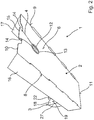
- FIGS. 1 and 2 show a goods feed system 1 according to a first embodiment of the present invention, which has a rail 2, a slide 3 and a tensioning means 4 as main components.
- the rail 2 shown in detail is folded from a one-piece blank made of cardboard or corrugated cardboard. It comprises an elongated bottom 5 extending in a longitudinal direction L, which has an underside 6, an upper side 7, two opposite longitudinal sides 8 and 9, a front end 10 and a rear end 11 and is used to hold goods.
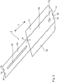
- the floor 5 consists of a lower floor layer 5a and an upper floor layer 5b, which have essentially the same external dimensions, along the rear Front side 11 of the bottom 5 connected to one another and in the direction of arrow A in Figure 3 are folded on top of each other.
- the lower floor layer 5a is provided in the front area with a through hole 12 arranged in the center in the present case.
- an elongated through opening 13 is formed which, in the folded state of the rail 2, is positioned congruently with the through hole 12 and, proceeding therefrom, extends to the rear in the longitudinal direction L.
- the rail 2 comprises two upwardly projecting side walls 16 and 17, which adjoin the longitudinal sides 8 and 9 of the floor 5 and in the present case extend over the entire length of the floor 5. To assemble the rail 2 starting from the in Figure 3 The blank shown, the upper bottom layer 5b is folded onto the lower bottom layer 5a. Furthermore, the side walls 17 and 17 are each folded up by 90 °.
- the carriage 3 shown in detail is also made from a single blank of cardboard or corrugated cardboard.
- the goods feed system 1 comprises a wall 18 which extends essentially vertically between the longitudinal sides 8 and 9 of the bottom 5 of the rail 2, the width of which is selected to be slightly smaller than the distance between the longitudinal sides 8 and 9 and the front of which has a goods contact surface 19 and a bottom wall 20 connected to the wall 18.
- the wall 18 in the present case is inclined at an angle ⁇ to the bottom wall 20, the angle ⁇ preferably being in the range between 0 and 15 °.
- an upwardly projecting projection 22 is arranged, which is provided with undercuts 23 and is used to fasten the clamping means 4.
- the bottom wall 20 of the carriage 3 has a multi-layer design and comprises a lower bottom wall layer 20a and an upper bottom wall layer 20b, on which a tab 24 is provided on the end face.
- a through opening 25 is formed for guiding the tensioning means 4 through, which is formed by two corresponding recesses in the lower bottom wall layer 20a on the one hand and in the upper bottom wall layer 20b on the other hand.
- the slide 3 further comprises two essentially vertically extending side walls 26 and 27 which laterally connect the wall 18 and the bottom wall 20 to one another.
- the side walls 26 and 27 are each provided with retaining projections 28 and 29 on the end face.
- the side walls 26 and 27 of the in Figure 5 The blank shown is folded over by 90 ° in a first step, whereupon the retaining projections 28 and 29 are also folded by 90 ° to one another so that they are arranged in a common plane, as shown in FIG Figure 6 is shown.
- the mutually facing edges of the retaining projections 28 and 29 together form a U-shaped recess 30 open at the end.
- the upper bottom wall layer 20b is folded onto the lower bottom wall layer 20 and the tab 24 in the through opening 21 of the wall 18 positioned.
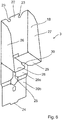
- the holding projections 28 and 29 are then in this state, as shown in FIG Figure 7 is shown, received between the lower bottom wall layer 20a and the upper bottom wall layer 20b, wherein the position of the U-shaped recess 30 corresponds to the position of the through opening 20.
- the tensioning means 4 which is provided as a ring-shaped rubber band, is placed from above around the projection 15 provided on the front face 10 of the base 5, from below through the through-hole 12 positioned in the lower base layer 5a of the rail 2 , guided through the elongated through opening 13 provided in the upper bottom layer 5b of the bottom 5 of the rail 2 to the slide 3, there threaded through the through opening 21 provided in the wall 18 and from below through the through opening 25 arranged in the bottom wall 20 of the slide 3 and placed around the projection 22 provided in the upper region of the wall 18.
- the slide 3 is pulled by the clamping means 4 in the direction of the front end face 10 of the base 5 of the rail 2.
- the lower floor layer 5a and the upper floor layer 5b of the rail 2 are pressed onto one another by the clamping means 4.
- the goods feed system 1 can now be arranged in a known manner in a goods packaging or in a display made of cardboard or corrugated cardboard (not shown) and then fitted with goods.
- the goods arranged on the upper side 7 of the base 5 are then pressed by the carriage 3 in the direction of the front edge of the outer packaging or the display, so that the foremost goods come to rest there. If goods are removed from the goods feed system 1, the carriage 3 is automatically pulled forward by the clamping means 4, so that the goods remaining in the goods feed system 1 are pushed forward.
- the carriage 3 of the previously described goods feed system 1 can also be arranged on the rail 2 rotated by 180 °.
- the clamping means 4 is then placed from above around the projection 15 provided on the front end face 10 of the base 5 of the rail 2, from below through the in the through hole 12 positioned in the lower bottom layer 5a of the rail 2, guided through the elongated through opening 13 provided in the upper bottom layer 5b of the bottom 5 of the rail 2 to the carriage 3, there threaded from below through the through opening 2 arranged in the bottom wall 20 of the carriage 3, then passed through the through opening 21 provided in the wall 18 and finally placed around the projection 22 provided in the upper region of the wall 18 from behind.
- This variant is characterized in that goods can also be positioned on the bottom wall 20 of the carriage 3 between the side walls 26 and 27, whereby the goods receiving capacity is increased.
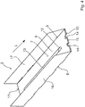
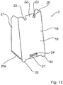
- the Figures 10 to 12 show a goods feed system 1 according to a second embodiment of the present invention or its components.
- the structure of this goods feed system 1 basically corresponds to the structure of the previously described goods feed system 1.
- a first difference is that in the in Figure 10
- the goods feed system 1 shown comprises the rail 2 and the carriage 3 locking means in order to lock the carriage 3 temporarily in its rear carriage position.
- the locking means are formed by two detent recesses 31, which are spaced apart from one another and formed in the upper side 7 of the rail 2 in the area of the rear carriage position, and two detent projections 32 protruding downward from the bottom wall 20 of the carriage and which can optionally be brought into engagement with the detent recesses 31 as it is in Figure 10 is shown.
- the advantage of such locking means is that the goods feed system can be more easily equipped with goods in the locked carriage position.
- the bottom wall 20 can also be provided with latching recesses and the rail 2 with latching projections protruding upwards from its top 7, even if this is not shown here.
- the rail 2 of the in Figure 10 The goods feed system shown has no side walls 16 and 17.
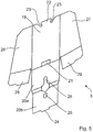
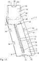
- the Figures 13 to 18 show a goods feed system 1 according to a third embodiment of the present invention or its components.
- the structure of this goods feed system basically corresponds to the structure of the goods feed system 1 according to the first embodiment described above.
- a first difference is that the lower floor layer 5a and the upper floor layer 5b of the floor 5 of the rail 2 are connected to one another along the front end face 10 of the floor 5.
- the in Figure 13 The goods feed system 1 shown has only a single side wall 17 which extends along the longitudinal side 9 of the base 5 of the rail 2 and projects upwards from the base 5.
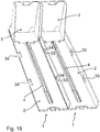
- the longitudinal sides 8 and 9 of the base 5 of the rail 2 are provided with connecting elements which are designed to connect the bases 5 of the rails 2 of goods feed systems 1 arranged laterally adjacent to one another, as shown in FIG Figure 19 is shown.
- the connecting elements are designed in the form of connecting projections 33 and connecting recesses 34, the dimensions of which are adapted to one another and which interlock in a form-fitting manner.
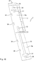
- the rail 2 and the carriage 3 similar to the goods feed system 1 according to the second embodiment described above, comprise locking means in order to temporarily lock the carriage 3 in its rear carriage position.
- these locking means are formed by a single locking recess 31 provided on the upper side 7 of the rail 2 and a single locking projection 32 protruding from the bottom wall 20 of the carriage 3, which can engage the locking recess 31, as shown in FIG Figure 13 is shown.
- the locking recess 31 is T-shaped in the illustrated case, even if other shapes are basically conceivable.
- the locking projection 32 is through a with a central Formed opening for passing through the tensioning means 4 provided tab which is formed on the front edge of the bottom wall 20 of the carriage 3 and bent downwards and backwards.
- a slide platform 35 is formed on the rear face of the rail 2, which in the present case consists of an upwardly and forwardly folded platform tab 36 extending parallel to the top side 7 of the base 5, with a downwardly protruding retaining lug 37 in a base 5 of the Rail 2 provided holding opening is fixed.
- the carriage platform 35 holds the two floor layers 5a and 5b of the floor 5 of the rail 2 together.
- it picks up the slide 3 in its rear slide position and tilts its front area downwards in order to press the locking projection 32 of the slide 3 into the locking recess 31 of the rail 2, which realizes a particularly good locking of the slide 3 in the rear slide position becomes.
- the slide 3 only has to be pressed slightly backwards so that the locking projection 32 is brought out of engagement with the locking recess 31. Yet another difference is that the carriage 3 is rotated by 180 ° compared to the previously described embodiments, which means that more space is available for receiving goods, since additional goods can be arranged between the side walls 27 and 27 of the carriage 3. With this arrangement of the slide 3, the through opening 21 for guiding the clamping means 4 through can be dispensed with. Further minor differences between the individual blanks of the rail 2 and the carriage 3 can be seen from the drawing.
Description
Die vorliegende Erfindung betrifft ein Warenvorschubsystem für die abverkaufsgerechte Präsentation von Waren, umfassend eine Schiene mit einem länglichen, sich in einer Längsrichtung erstreckenden Boden, der eine Unterseite, eine Oberseite, zwei einander gegenüber angeordnete Längsseiten, eine hintere Stirnseite sowie eine vordere Stirnseite aufweist und zur Aufnahme von Waren dient, einen eine Warenanlagefläche definierenden Schlitten, der auf dem Boden zwischen den Stirnseiten in Längsrichtung zwischen einer hinteren und einer vorderen Position bewegbar ist, und ein Spannmittel, das im vorderen Bereich der Schiene sowie an dem Schlitten befestigt ist und im gespannten Zustand den Schlitten in Richtung des vorderen Bereichs der Schiene vorspannt.The present invention relates to a goods feed system for the sales-appropriate presentation of goods, comprising a rail with an elongated bottom extending in a longitudinal direction, which has an underside, an upper side, two longitudinal sides arranged opposite one another, a rear end face and a front end face and for Receipt of goods is used, a carriage defining a goods contact surface, which is movable on the floor between the end faces in the longitudinal direction between a rear and a front position, and a clamping means which is attached in the front region of the rail and on the carriage and in the clamped state biases the carriage towards the front of the rail.
Warenvorschubsysteme der eingangs genannten Art sind im Stand der Technik in verschiedensten Ausgestaltungen bekannt. Sie dienen dazu, Waren stets an der vorderen Kante eines Regals oder eines Displays zu positionieren. Dies verbessert zum einen das äußere Erscheinungsbild des Regals oder Displays. Zum anderen wird den Kunden auch der Warenzugriff erleichtert.Goods feed systems of the type mentioned are known in the prior art in a wide variety of configurations. They are used to always position goods on the front edge of a shelf or a display. On the one hand, this improves the external appearance of the shelf or display. On the other hand, it is also easier for customers to access goods.
Die Schienen und Schlitten von Warenvorschubsystemen, die dauerhaft in Regalen platziert werden, sind meist aus Kunststoff hergestellt, wobei die Vorspannung des Schlittens in Richtung des vorderen Bereichs der Schiene durch metallische Federelemente realisiert wird. Ein wesentlicher Nachteil solcher Warenvorschubsysteme besteht allerdings darin, dass diese sehr kostspielig sind. Dies ist auch der Grund dafür, dass sie nicht für Display-Systeme eingesetzt werden, also für meist aus Wellpappe hergestellte Aufsteller, in denen Waren nur temporär im Rahmen von Verkaufsaktionen präsentiert werden.The rails and carriages of goods feed systems, which are permanently placed on shelves, are usually made of plastic, with the pretensioning of the carriage in the direction of the front area of the rail using metallic spring elements. A major disadvantage of such goods feed systems, however, is that they are very expensive. This is also the reason why they are not used for display systems, i.e. for displays mostly made of corrugated cardboard, in which goods are only temporarily presented as part of sales promotions.
Ferner sind Warenvorschubsysteme aus Karton oder Wellpappe bekannt, die zur einmaligen Verwendung direkt in eine Warenumverpackung oder in ein Display eingesetzt werden. Ein solches Warenvorschubsystem ist beispielsweise in der
Ein weiteres Warenvorschubsystem ist in der Druckschrift
Ausgehend von diesem Stand der Technik ist es eine Aufgabe der vorliegenden Erfindung, ein Warenvorschubsystem der eingangs genannten Art mit alternativem Aufbau zu schaffen.Based on this prior art, it is an object of the present invention to provide a goods feed system of the type mentioned at the beginning with an alternative structure.
Zur Lösung dieser Aufgabe schafft die vorliegende Erfindung ein Warenvorschubsystem für die abverkaufsgerechte Präsentation von Waren, umfassend eine Schiene mit einem länglichen, sich in einer Längsrichtung erstreckenden Boden, der eine Unterseite, eine Oberseite, zwei einander gegenüber angeordnete Längsseiten, eine hintere Stirnseite sowie eine vordere Stirnseite aufweist und zur Aufnahme von Waren dient, wobei die Schiene einteilig aus einem Zuschnitt aus Pappe oder Wellpappe hergestellt ist, einen eine Warenanlagefläche definierenden Schlitten, der auf dem Boden zwischen den Stirnseiten in Längsrichtung zwischen einer hinteren und einer vorderen Schlittenposition bewegbar ist, und ein Spannmittel, das im vorderen Bereich der Schiene sowie an dem Schlitten befestigt ist und im gespannten Zustand den Schlitten in Richtung des vorderen Bereichs der Schiene vorspannt, wobei der Boden eine untere, mit einem Durchgangsloch versehene Bodenlage und zumindest eine auf die untere Bodenlage gefaltete obere Bodenlage aufweist, in der im Zuschnitt eine längliche Durchgangsöffnung ausgebildet ist, die deckungsgleich zum Durchgangsloch positioniert ist und sich ausgehend von diesem in Längsrichtung nach hinten zur hinteren Schlittenposition erstreckt, und wobei das Spannmittel ausgehend von seiner Befestigung im vorderen Bereich der Schiene durch das Durchgangsloch und die längliche Durchgangsöffnung zum Schlitten geführt ist.To solve this problem, the present invention creates a goods feed system for the sales-appropriate presentation of goods, comprising a rail with an elongated base extending in a longitudinal direction, a lower side, an upper side, two opposite longitudinal sides, a rear face and a front Has the end face and serves to hold goods, the rail is made in one piece from a blank of cardboard or corrugated cardboard, a carriage defining a goods contact surface, which is movable on the floor between the end faces in the longitudinal direction between a rear and a front carriage position, and a tensioning means in the front area of the rail and on the carriage is attached and in the tensioned state biases the carriage in the direction of the front area of the rail, the bottom having a lower bottom layer provided with a through hole and at least one upper bottom layer folded onto the lower bottom layer, in which an elongated through opening is formed in the blank, which is positioned congruently to the through hole and extends from this in the longitudinal direction backwards to the rear slide position, and wherein the clamping means ge based on its attachment in the front region of the rail through the through hole and the elongated through opening to the slide leads is.
Dank dieser erfindungsgemäßen Konstruktion kann die gesamte Schiene mehrlagig ausgeführt werden, insbesondere zweilagig, was insgesamt eine hohe Stabilität, insbesondere Formstabilität nach sich zieht. Darüber hinaus kann die gesamte obere Fläche der Schiene als Aufnahmefläche für den Schlitten dienen, was dazu führt, dass die Warenanlagefläche des Schlittens vergleichsweise groß gewählt werden und der Breite der Schiene im Wesentlichen entsprechen kann. Somit kann die Spannkraft des Spannmittels sehr gleichmäßig über den Schlitten auf die an der Warenanlagefläche anliegende Ware übertragen werden.Thanks to this construction according to the invention, the entire rail can be designed in multiple layers, in particular in two layers, which results in overall high stability, in particular dimensional stability. In addition, the entire upper surface of the rail can serve as a receiving surface for the carriage, which means that the goods contact surface of the carriage can be selected to be comparatively large and can essentially correspond to the width of the rail. Thus, the clamping force of the clamping device can be transmitted very evenly via the carriage to the goods resting on the goods contact surface.
Gemäß einer Ausgestaltung der vorliegenden Erfindung ist die Schiene an ihrer vorderen Stirnseite mit wenigstens einem insbesondere mit zumindest einem Hinterschnitt ausgebildeten, nach vorne oder aufwärts vorstehenden Vorsprung versehen, der zur Befestigung des Spannmittels dient. Der Vorsprung kann insbesondere an der oberen Bodenlage ausgebildet sein, so dass die Bodenlagen durch das Spannmittel gegeneinander gedrückt werden. Besser noch ist der Vorsprung durch zwei Teilvorsprünge gebildet, die im Wesentlichen deckungsgleich einerseits an der unteren Bodenlage und andererseits an der oberen Bodenlage ausgebildet sind. Auf diese Weise wird eine noch bessere Stabilität erzielt.According to one embodiment of the present invention, the rail is provided on its front face with at least one projection, in particular formed with at least one undercut, protruding forwards or upwards, which is used to fasten the clamping means. The projection can in particular be formed on the upper floor layer, see above that the floor layers are pressed against each other by the clamping device. Even better, the projection is formed by two partial projections which are formed essentially congruently on the one hand on the lower floor layer and on the other hand on the upper floor layer. In this way, even better stability is achieved.
Die Schiene weist bevorzugt zumindest eine aufwärts vorstehende Seitenwand auf, die sich an eine der Längsseiten des Bodens anschließt und sich insbesondere über die gesamte Länge des Bodens erstreckt. Dank einer solchen Seitenwand wird in einfacher Weise eine Führung der auf der Schiene angeordneten Waren realisiert. Ist nur eine einzelne Seitenwand vorgesehen, so kann eine entsprechende Seitenwand eines benachbart angeordneten Warenvorschubsystems die Führung der Ware auf der Schiene auf der anderen Seite übernehmen. Ebenso ist es natürlich auch möglich, jede Schiene mit zwei einander gegenüber und sich parallel zueinander erstreckenden Seitenwänden zu versehen.The rail preferably has at least one upwardly projecting side wall which adjoins one of the longitudinal sides of the floor and in particular extends over the entire length of the floor. Thanks to such a side wall, the goods arranged on the rail are guided in a simple manner. If only a single side wall is provided, a corresponding side wall of an adjacently arranged goods feed system can take over the guiding of the goods on the rail on the other side. It is of course also possible to provide each rail with two side walls extending opposite one another and parallel to one another.
Vorteilhaft ist die Schiene ohne weitere Hilfsmittel montiert. Entsprechend lässt sich die Schiene einfach fertigen und montieren. Es sollte allerdings klar sein, dass bei der Montage Befestigungsmittel verwendet werden können, insbesondere in Form von Klebstoff, Druckösen, Klebebändern, Nieten oder dergleichen.The rail is advantageously mounted without any further aids. Accordingly, the rail can be easily manufactured and assembled. However, it should be clear that fastening means can be used during assembly, in particular in the form of adhesive, pressure eyelets, adhesive tapes, rivets or the like.
Gemäß einer Ausgestaltung der vorliegenden Erfindung ist die obere Bodenlage insbesondere stirnseitig mit der unteren Bodenlage verbunden und auf die untere Bodenlage gefaltet, was zu einem einfachen und stabilen Aufbau des Schlittens führt.According to one embodiment of the present invention, the upper floor layer is connected in particular at the end to the lower floor layer and folded onto the lower floor layer, which leads to a simple and stable construction of the carriage.
Der Schlitten weist bevorzugt eine sich im Wesentlichen vertikal zwischen den Längsseiten des Bodens der Schiene erstreckende Wand, welche die Warenanlagefläche definiert, und eine mit dieser verbundene Bodenwand auf, die auf dem Boden der Schiene aufliegt, wodurch ein einfacher und doch stabiler Aufbau erzielt wird.The carriage preferably has a wall which extends essentially vertically between the longitudinal sides of the bottom of the rail and which the Defined goods contact surface, and a bottom wall connected to this, which rests on the bottom of the rail, whereby a simple and yet stable structure is achieved.
Im unteren Bereich der sich im Wesentlichen vertikal erstreckenden Wand des Schlittens ist vorteilhaft eine Durchgangsöffnung zum Hindurchführen des Spannmittels ausgebildet, so dass im unteren Bereich des Schlittens ein Eingriff mit dem Spannmittel stattfindet.In the lower area of the essentially vertically extending wall of the slide, a through opening for guiding through the clamping means is advantageously formed, so that the clamping means is engaged in the lower region of the slide.
Im oberen Bereich der sich im Wesentlichen vertikal erstreckenden Wand des Schlittens ist bevorzugt ein aufwärts vorstehender Vorsprung zur Befestigung des Spannmittels vorgesehen, der insbesondere mit zumindest einem Hinterschnitt versehen ist. Entsprechend findet auch im oberen Bereich des Schlittens ein Eingriff mit dem Spannmittel statt, wodurch eine optimale Kraftübertragung von der Warenanlagefläche des Schlittens auf die an dieser anliegende Ware realisierbar ist.In the upper region of the essentially vertically extending wall of the slide, an upwardly projecting projection is preferably provided for fastening the clamping means, which projection is in particular provided with at least one undercut. Correspondingly, there is also an engagement with the clamping means in the upper area of the slide, whereby an optimal transmission of force from the goods contact surface of the slide to the goods lying on it can be realized.
In der Bodenwand des Schlittens kann eine Durchgangsöffnung zum Hindurchführen des Spannmittels ausgebildet sein, was einer guten Kraftübertragung vom Spannmittel auf den Schlitten zuträglich ist.In the bottom wall of the slide, a through opening for passing the clamping means can be formed, which is conducive to good power transmission from the clamping means to the slide.
Der Schlitten weist vorteilhaft sich im Wesentlichen vertikal erstreckende Seitenwände auf, welche die sich im Wesentlichen vertikal erstreckende Wand und die Bodenwand seitlich miteinander verbinden, wodurch die Stabilität des Schlittens weiter verbessert wird.The carriage advantageously has substantially vertically extending side walls which laterally connect the substantially vertically extending wall and the bottom wall to one another, whereby the stability of the carriage is further improved.
Die Bodenwand des Schlittens kann mehrlagig ausgebildet sein, was ebenfalls der Verbesserung der Stabilität des Schlittens dient.The bottom wall of the slide can have multiple layers, which also serves to improve the stability of the slide.
Bevorzugt sind Arretiermittel vorgesehen, die dazu ausgelegt sind, den Schlitten auf der Schiene in der hinteren Schlittenposition zu arretieren. Im arretierten Zustand kann das Warenvorschubsystem dann problemlos mit Ware bestückt werden, woraufhin dann die Arretierung aufgehoben wird, um den Warenvorschub zu aktivieren. Die Arretiermittel können beispielsweise zumindest einen von der Bodenwand des Schlittens abwärts vorstehenden Rastvorsprung einerseits und zumindest eine in der Schiene im Bereich der hinteren Schlittenposition ausgebildete, mit dem zumindest einen Rastvorsprung zusammenwirkende Rastaussparung andererseits umfassen, oder umgekehrt.Locking means are preferably provided which are designed to lock the slide on the rail in the rear slide position. In the locked state, the goods feed system can then be loaded with goods without any problems, whereupon the lock is released in order to activate the goods feed. The locking means can, for example, comprise at least one latching projection protruding downwards from the bottom wall of the slide and at least one latching recess formed in the rail in the region of the rear slide position and interacting with the at least one latching projection, or vice versa.
Vorteilhaft ist der Schlitten aus einem einzelnen Zuschnitt aus Pappe oder Wellpappe hergestellt und insbesondere ohne weitere Hilfsmittel montiert. Entsprechend lässt sich der Schlitten einfach fertigen und montieren. Es sollte allerdings klar sein, dass bei der Montage Befestigungsmittel verwendet werden können, insbesondere in Form von Klebstoff, Druckösen, Klebebändern, Nieten oder dergleichenThe carriage is advantageously made from a single blank of cardboard or corrugated cardboard and, in particular, is assembled without any further aids. Accordingly, the slide can be easily manufactured and assembled. However, it should be clear that fastening means can be used during assembly, in particular in the form of adhesive, pressure eyelets, adhesive tapes, rivets or the like
Gemäß einer Ausgestaltung der vorliegenden Erfindung sind an den Längsseiten des Bodens der Schiene Verbindungselemente vorgesehen, die dazu ausgelegt sind, die Böden der Schienen seitlich benachbart zueinander angeordneter Warenvorschubsysteme miteinander zu verbinden, wobei die Verbindungselemente insbesondere in Form von Verbindungsvorsprüngen und Verbindungsaussparungen ausgebildet sind, deren Abmessungen aufeinander angepasst sind und die insbesondere formschlüssig ineinander greifen.According to one embodiment of the present invention, connecting elements are provided on the longitudinal sides of the bottom of the rail, which are designed to connect the bottoms of the rails to each other laterally adjacent to each other goods feed systems, wherein the connecting elements are designed in particular in the form of connecting projections and connecting recesses, the dimensions of which are adapted to one another and which in particular interlock with one another in a form-fitting manner.
Das Spannmittel ist bevorzugt durch ein ringförmiges Gummiband gebildet.The tensioning means is preferably formed by an annular rubber band.
Weitere Vorteile und Merkmale der vorliegenden Erfindung werden anhand der nachfolgenden Beschreibung verschiedener Ausführungsformen erfindungsgemäßer Warenvorschubsysteme unter Bezugnahme auf die beiliegende Zeichnung deutlich. Darin ist
-
Figur 1 -
Figur 2Figur 1 -
Figur 3Figur 1 -
Figur 4Figur 3 -
Figur 5Figur 1 -
Figur 6Figur 5 -
Figur 7Figur 5 -
Figur 8Figur 7 -
Figur 9Figur 1 -
Figur 10 -
Figur 11Figur 10 -
Figur 12Figur 10 -
Figur 13 -
Figur 14Figur 13 -
Figur 15Figur 13 -
Figur 16Figur 13 -
Figur 17Figur 13 -
Figur 18Figur 17 -
Figur 19Figur 13 , deren Schlitten sich jeweils in einer arretierten hinteren Schlittenposition befinden.
-
Figure 1 a perspective view of a goods feeding system according to a first embodiment of the present invention, wherein a carriage of the system is in a rear carriage position; -
Figure 2 a perspective bottom view of the inFigure 1 illustrated goods feed system; -
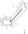
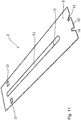
Figure 3 a perspective top view of a blank of a rail of the inFigure 1 illustrated goods feed system in the unfolded state; -
Figure 4 a perspective view of the inFigure 3 shown rail in the folded state; -
Figure 5 a perspective view of a blank of a carriage of the inFigure 1 illustrated goods feed system in the unfolded state; -
Figure 6 a perspective view of the inFigure 5 shown carriage in the partially folded state; -
Figure 7 a perspective view of the inFigure 5 shown carriage in the fully folded state; -
Figure 8 a further perspective view of the inFigure 7 illustrated arrangement; -
Figure 9 a perspective rear view of the inFigure 1 illustrated goods advancing system, wherein the carriage is in a forward carriage position; -
Figure 10 a perspective view of a goods feeding system according to a second embodiment of the present invention, wherein a carriage is in a locked rear carriage position; -
Figure 11 a perspective view of a rail of the inFigure 10 goods feed system shown in the fully folded state; -
Figure 12 a perspective view of a carriage of the inFigure 10 goods feed system shown in the fully folded state; -
Figure 13 a perspective view of a goods feed system according to a third embodiment of the present invention, wherein a carriage is in a locked rear carriage position; -
Figure 14 a perspective bottom view of the inFigure 13 illustrated arrangement; -
Figure 15 a perspective view of the inFigure 13 goods feed system shown, wherein the carriage is in a central carriage position; -
Figure 16 a perspective view of a blank of a rail of the inFigure 13 illustrated goods feed system in the unfolded state; -
Figure 17 a perspective view of a blank of a carriage of the inFigure 13 illustrated goods feed system in the unfolded state; -
Figure 18 a perspective view of the inFigure 17 shown carriage in the folded state and -
Figure 19 a perspective view of two adjacently arranged, interconnected goods feed systems according toFigure 13 whose carriages are each in a locked rear carriage position.
Gleiche Bezugsziffern beziehen sich nachfolgend auf gleiche oder gleichartige Bauteile bzw. Komponenten.The same reference numbers refer to the same or similar parts or components below.
Die
Die in den
Der in den
Zur Erzeugung der in den
An dieser Stelle sei darauf hingewiesen, dass der Schlitten 3 des zuvor beschriebenen Warenvorschubsystems 1 auch um 180° gedreht auf der Schiene 2 angeordnet werden kann. Bei dieser Variante ist das Spannmittel 4 dann von oben um den an der vorderen Stirnseite 10 des Bodens 5 der Schiene 2 vorgesehenen Vorsprung 15 gelegt, von unten durch das in der unteren Bodenlage 5a der Schiene 2 positionierte Durchgangsloch 12 gefädelt, durch die in der oberen Bodenlage 5b des Bodens 5 der Schiene 2 vorgesehene längliche Durchgangsöffnung 13 zum Schlitten 3 geführt, dort von unten durch die in der Bodenwand 20 des Schlittens 3 angeordnete Durchgangsöffnung 2 gefädelt, dann durch die in der Wand 18 vorgesehene Durchgangsöffnung 21 geführt und schließlich von hinten um den im oberen Bereich der Wand 18 vorgesehenen Vorsprung 22 gelegt. Diese Variante zeichnet sich dadurch aus, dass Ware zusätzlich auf der Bodenwand 20 des Schlittens 3 zwischen den Seitenwänden 26 und 27 positioniert werden kann, wodurch die Warenaufnahmekapazität erhöht wird.At this point it should be pointed out that the
Die
Die
Wesentliche Vorteile der zuvor beschriebenen Warenvorschubsysteme bestehen insbesondere in der vergleichsweise hohen Festigkeit und Formstabilität, der geringen Anzahl an Einzelteilen, der preiswerten Herstellbarkeit unter Verwendung einfacher Maschinen, der einfachen Montierbarkeit, der flexiblen Einsatzbarkeit in Umverpackungen und Displays und der vollflächigen Bedruckbarkeit, um nur einige Aspekte zu nennen.Significant advantages of the goods feed systems described above consist in particular in the comparatively high strength and dimensional stability, the small number of individual parts, the inexpensive manufacturability using simple machines, the simple assembly, the flexible Can be used in outer packaging and displays and can be printed over the entire surface, to name just a few aspects.
Es sollte klar sein, dass die zuvor beschriebenen Ausführungsformen nur als Beispiele dienen und den Schutzbereich der vorliegenden Erfindung nicht einschränken, der durch die beiliegenden Ansprüche definiert ist. So erfolgt die Montage der Schiene 2, des Schlittens 3 und des Spannmittel 4 bei den beschriebenen Ausführungsformen allein durch Falten. Es sollte jedoch klar sein, dass zusätzliche Montagehilfsmittel verwendet werden können, wie beispielsweise Klebstoffe, Druckösen, Klebebänder, Nieten oder dergleichen. Ferner sei darauf hingewiesen, dass die Abmessungen der Schiene 2 und des Schlittens 3 verwendungsspezifisch verändert, insbesondere an die aufzunehmenden Waren angepasst werden können.It should be understood that the embodiments described above serve only as examples and do not limit the scope of the present invention, which is defined by the appended claims. The assembly of the
Claims (15)
- Dispensing system (1) for the sales-oriented presentation of goods, comprising a rail (2) with an elongated base (5) extending in a longitudinal direction (L), which has an underside (6), an upper side (7), two longitudinal sides (8, 9), that are arranged opposite one another, a rear end face (11) and a front end face (10) and serves to receive goods, wherein the rail (2) is produced in one piece from a blank of cardboard or corrugated cardboard, a carriage (3) defining a product contact surface (19), which is movable on the base (5) between the end faces (8, 9) in the longitudinal direction (L) between a rear and a front carriage position and a tensioning means (4) that is fastened in the front region of the rail (2) as well as to a carriage (3) and in the tensioned state, pre-loads the carriage (3) in a direction towards the front end region of the rail (2), the base (5) having a lower base layer (5a) that is provided with a through-hole (12) and at least one upper base layer (5b) that is folded onto the lower base layer (5a), in which an elongated through-opening (13) is formed that is positioned congruently with the through-hole (12) and, starting from the latter, extends in the longitudinal direction (L) rearwardly to the rear carriage position, and wherein the clamping means (4), starting from its attachment in the front region of the rail (2) is guided through the through-hole (12) and the longitudinal through-opening (13) to the carriage (3), characterized in that the longitudinal through-opening (13) is formed in the blank.
- Dispensing system (1) according to claim 1, characterized in that the rail (2) at its front-end face (10) is provided with at least one forward- or upward-pointing projection (15), which in particular is formed with at least one undercut (14), that serves to fasten the tensioning means (4).
- Dispensing system (1) according to one of the preceding claims, characterized in that the rail (2) has at least one upward-projecting side wall (16, 17), which adjoins to one of the longitudinal sides (8, 9) of the base (5) and in particular extends over the entire length of the base (5).
- Dispensing system (1) according to one of the preceding claims, characterized in that the rail (2) is installed without any further aids.
- Dispensing system (1) according to claim 4, characterized in that the upper base layer (5b) is connected to the lower base layer (5a) in particular at the end face thereof and is folded onto the lower base layer (5a).
- Dispensing system (1) according to any of the preceding claims, characterized in that the carriage (3) has a wall (18) extending substantially vertically in-between the longitudinal sides (8, 9) of the base (5) of the rail (2) that defines the product contact surface (19) and has a bottom wall (20) connected thereto that rests on the base (5) of the rail (2).
- Dispensing system (1) according to claim 6, characterized in that a through-opening (21) is formed in the lower region of the substantially vertically extending wall (18) in order to guide through the fastening means (4).
- Dispensing system (1) according to one of claims 6 or 7, characterized in that an upwardly projecting projection (22), which is in particular provided with at least one undercut (23), is provided in the upper region of the substantially vertically extending wall (18) in order to fasten the fastening means (4).
- Dispensing system (1) according to one of claims 6 to 8, characterized in that a through-opening (25) is formed in the base wall (20) of the carriage (3) in order to guide through the fastening means (4).
- Dispensing system (1) according to one of claims 6 to 9, characterized in that the carriage (3) comprises substantially vertically extending side walls (26, 27), which laterally connect the substantially vertically extending wall (18) and the base wall (20) to another from the side.
- Dispensing system (1) according to one of claims 6 to 10, characterized in that the base wall (20) of the carriage (3) is formed with several layers.
- Dispensing system (1) according to one of the preceding claims, characterized in that locking means are provided, which are designed to lock the carriage (3) on the rail (2) in the rear carriage position.
- Dispensing system (1) according to one of the preceding claims, characterized in that the carriage (3) is produced from a single blank of cardboard or corrugated cardboard.
- Dispensing system (1) according to one of the preceding claims, characterized in that connecting elements are provided on the longitudinal sides (8, 9) of the base (5) of the rail (2), which are designed in order to connect the base (5) of the rails (2) of dispensing systems (1) that are allocated sidewards and adjacent to another, wherein the connecting elements are in particular formed in the form of connecting projections (33) and connecting recesses (34), the dimensions of which are adapted to one another and which in particular engage in one another in a form-fitting manner.
- Dispensing system (1) according to one of the preceding claims, characterized in that the fastening means is formed by an annular rubber band.
Priority Applications (1)
| Application Number | Priority Date | Filing Date | Title |
|---|---|---|---|
| EP18166691.8A EP3552524B1 (en) | 2018-04-10 | 2018-04-10 | Dispensing system with pusher apparatus |
Applications Claiming Priority (1)
| Application Number | Priority Date | Filing Date | Title |
|---|---|---|---|
| EP18166691.8A EP3552524B1 (en) | 2018-04-10 | 2018-04-10 | Dispensing system with pusher apparatus |
Publications (2)
| Publication Number | Publication Date |
|---|---|
| EP3552524A1 EP3552524A1 (en) | 2019-10-16 |
| EP3552524B1 true EP3552524B1 (en) | 2020-12-02 |
Family
ID=61965832
Family Applications (1)
| Application Number | Title | Priority Date | Filing Date |
|---|---|---|---|
| EP18166691.8A Active EP3552524B1 (en) | 2018-04-10 | 2018-04-10 | Dispensing system with pusher apparatus |
Country Status (1)
| Country | Link |
|---|---|
| EP (1) | EP3552524B1 (en) |
Family Cites Families (4)
| Publication number | Priority date | Publication date | Assignee | Title |
|---|---|---|---|---|
| FR2762502B1 (en) * | 1997-04-29 | 1999-07-16 | Smurfit Socar Sa | NEW TRAY IN SEMI-RIGID MATERIAL FOR THE EXHIBITION FOR SALE OF VARIOUS ITEMS |
| DE102004015701B3 (en) | 2004-03-29 | 2005-07-21 | Thimm Verpackung Gmbh & Co. Kg | Sales pack for presentation of goods has raised parts forming part of separate insert of pack with bottom piece lying on bottom of pack |
| PL227639B1 (en) * | 2014-05-28 | 2018-01-31 | Werner Kenkel Spólka Z Ograniczona Odpowiedzialnoscia | Exhibition platform |
| EP3176102B1 (en) * | 2015-12-01 | 2018-01-10 | Saica Pack, S.L. | Display tray with integrated handle |
-
2018
- 2018-04-10 EP EP18166691.8A patent/EP3552524B1/en active Active
Non-Patent Citations (1)
| Title |
|---|
| None * |
Also Published As
| Publication number | Publication date |
|---|---|
| EP3552524A1 (en) | 2019-10-16 |
Similar Documents
| Publication | Publication Date | Title |
|---|---|---|
| DE2633972C3 (en) | Arrangement for connecting two components | |
| EP3094568B1 (en) | Container for transporting goods and device for dividing such a container | |
| DE102016007854B4 (en) | Recording device with roller blind | |
| DE202007011927U1 (en) | Product display system | |
| DE2830676C2 (en) | Ski holding device | |
| DE202007010297U1 (en) | Goods carrier with subdivision arrangement | |
| DE4237124C2 (en) | Magazine for replacement blades | |
| CH624285A5 (en) | Storage box for sorted small parts which are to be stored | |
| DE1943621A1 (en) | Deformable, stackable locking clip for lacing, strapping or the like. | |
| EP3865716B1 (en) | Clamp for a detachable connection of construction elements | |
| DE4417857C2 (en) | Fixing device for variable fixing of cargo | |
| EP3552524B1 (en) | Dispensing system with pusher apparatus | |
| DE3139287A1 (en) | Connecting plate | |
| DE2644040C2 (en) | Angle connection for components, in particular profile strips, profile supports and the like. | |
| DE102017128562A1 (en) | Shelf box with locking stops | |
| DE19944654A1 (en) | Assembly unit | |
| DE2928118C2 (en) | Control panel element, in particular automatic circuit breaker or disconnector, designed for side-by-side fastening on a mounting rail | |
| EP2427080A1 (en) | Kit for a furniture drawer pull-out guide | |
| DE102011101281B3 (en) | Locking device for vehicle seat for motor car, has locking plates provided on longitudinal sides respectively, where number of teeth on one longitudinal side is different from number of teeth on another longitudinal side | |
| EP3852579A1 (en) | Drawer and unit made up of a pull-out guide and a drawer | |
| EP3973818A1 (en) | Drawer side wall | |
| EP3623219B1 (en) | Profile for securing a load and loading area for receiving cargo | |
| EP0185201A1 (en) | Drawer made of plastics material | |
| DE3500542A1 (en) | PLUG DIFFERENTIAL DIVISION OF DRAWERS OR THE LIKE. | |
| EP3735150B1 (en) | Assembly made of a bearing web for a drawer base and a holding device |
Legal Events
| Date | Code | Title | Description |
|---|---|---|---|
| PUAI | Public reference made under article 153(3) epc to a published international application that has entered the european phase |
Free format text: ORIGINAL CODE: 0009012 |
|
| STAA | Information on the status of an ep patent application or granted ep patent |
Free format text: STATUS: THE APPLICATION HAS BEEN PUBLISHED |
|
| AK | Designated contracting states |
Kind code of ref document: A1 Designated state(s): AL AT BE BG CH CY CZ DE DK EE ES FI FR GB GR HR HU IE IS IT LI LT LU LV MC MK MT NL NO PL PT RO RS SE SI SK SM TR |
|
| AX | Request for extension of the european patent |
Extension state: BA ME |
|
| STAA | Information on the status of an ep patent application or granted ep patent |
Free format text: STATUS: REQUEST FOR EXAMINATION WAS MADE |
|
| 17P | Request for examination filed |
Effective date: 20191112 |
|
| RBV | Designated contracting states (corrected) |
Designated state(s): AL AT BE BG CH CY CZ DE DK EE ES FI FR GB GR HR HU IE IS IT LI LT LU LV MC MK MT NL NO PL PT RO RS SE SI SK SM TR |
|
| STAA | Information on the status of an ep patent application or granted ep patent |
Free format text: STATUS: EXAMINATION IS IN PROGRESS |
|
| 17Q | First examination report despatched |
Effective date: 20200408 |
|
| GRAP | Despatch of communication of intention to grant a patent |
Free format text: ORIGINAL CODE: EPIDOSNIGR1 |
|
| STAA | Information on the status of an ep patent application or granted ep patent |
Free format text: STATUS: GRANT OF PATENT IS INTENDED |
|
| INTG | Intention to grant announced |
Effective date: 20200827 |
|
| GRAS | Grant fee paid |
Free format text: ORIGINAL CODE: EPIDOSNIGR3 |
|
| GRAA | (expected) grant |
Free format text: ORIGINAL CODE: 0009210 |
|
| STAA | Information on the status of an ep patent application or granted ep patent |
Free format text: STATUS: THE PATENT HAS BEEN GRANTED |
|
| AK | Designated contracting states |
Kind code of ref document: B1 Designated state(s): AL AT BE BG CH CY CZ DE DK EE ES FI FR GB GR HR HU IE IS IT LI LT LU LV MC MK MT NL NO PL PT RO RS SE SI SK SM TR |
|
| REG | Reference to a national code |
Ref country code: GB Ref legal event code: FG4D Free format text: NOT ENGLISH |
|
| REG | Reference to a national code |
Ref country code: AT Ref legal event code: REF Ref document number: 1339944 Country of ref document: AT Kind code of ref document: T Effective date: 20201215 Ref country code: CH Ref legal event code: EP |
|
| REG | Reference to a national code |
Ref country code: IE Ref legal event code: FG4D Free format text: LANGUAGE OF EP DOCUMENT: GERMAN |
|
| REG | Reference to a national code |
Ref country code: DE Ref legal event code: R096 Ref document number: 502018003151 Country of ref document: DE |
|
| REG | Reference to a national code |
Ref country code: NL Ref legal event code: FP |
|
| PG25 | Lapsed in a contracting state [announced via postgrant information from national office to epo] |
Ref country code: FI Free format text: LAPSE BECAUSE OF FAILURE TO SUBMIT A TRANSLATION OF THE DESCRIPTION OR TO PAY THE FEE WITHIN THE PRESCRIBED TIME-LIMIT Effective date: 20201202 Ref country code: RS Free format text: LAPSE BECAUSE OF FAILURE TO SUBMIT A TRANSLATION OF THE DESCRIPTION OR TO PAY THE FEE WITHIN THE PRESCRIBED TIME-LIMIT Effective date: 20201202 Ref country code: NO Free format text: LAPSE BECAUSE OF FAILURE TO SUBMIT A TRANSLATION OF THE DESCRIPTION OR TO PAY THE FEE WITHIN THE PRESCRIBED TIME-LIMIT Effective date: 20210302 Ref country code: GR Free format text: LAPSE BECAUSE OF FAILURE TO SUBMIT A TRANSLATION OF THE DESCRIPTION OR TO PAY THE FEE WITHIN THE PRESCRIBED TIME-LIMIT Effective date: 20210303 |
|
| PG25 | Lapsed in a contracting state [announced via postgrant information from national office to epo] |
Ref country code: SE Free format text: LAPSE BECAUSE OF FAILURE TO SUBMIT A TRANSLATION OF THE DESCRIPTION OR TO PAY THE FEE WITHIN THE PRESCRIBED TIME-LIMIT Effective date: 20201202 Ref country code: BG Free format text: LAPSE BECAUSE OF FAILURE TO SUBMIT A TRANSLATION OF THE DESCRIPTION OR TO PAY THE FEE WITHIN THE PRESCRIBED TIME-LIMIT Effective date: 20210302 Ref country code: PL Free format text: LAPSE BECAUSE OF FAILURE TO SUBMIT A TRANSLATION OF THE DESCRIPTION OR TO PAY THE FEE WITHIN THE PRESCRIBED TIME-LIMIT Effective date: 20201202 Ref country code: LV Free format text: LAPSE BECAUSE OF FAILURE TO SUBMIT A TRANSLATION OF THE DESCRIPTION OR TO PAY THE FEE WITHIN THE PRESCRIBED TIME-LIMIT Effective date: 20201202 |
|
| PG25 | Lapsed in a contracting state [announced via postgrant information from national office to epo] |
Ref country code: HR Free format text: LAPSE BECAUSE OF FAILURE TO SUBMIT A TRANSLATION OF THE DESCRIPTION OR TO PAY THE FEE WITHIN THE PRESCRIBED TIME-LIMIT Effective date: 20201202 |
|
| REG | Reference to a national code |
Ref country code: LT Ref legal event code: MG9D |
|
| PG25 | Lapsed in a contracting state [announced via postgrant information from national office to epo] |
Ref country code: CZ Free format text: LAPSE BECAUSE OF FAILURE TO SUBMIT A TRANSLATION OF THE DESCRIPTION OR TO PAY THE FEE WITHIN THE PRESCRIBED TIME-LIMIT Effective date: 20201202 Ref country code: EE Free format text: LAPSE BECAUSE OF FAILURE TO SUBMIT A TRANSLATION OF THE DESCRIPTION OR TO PAY THE FEE WITHIN THE PRESCRIBED TIME-LIMIT Effective date: 20201202 Ref country code: SM Free format text: LAPSE BECAUSE OF FAILURE TO SUBMIT A TRANSLATION OF THE DESCRIPTION OR TO PAY THE FEE WITHIN THE PRESCRIBED TIME-LIMIT Effective date: 20201202 Ref country code: LT Free format text: LAPSE BECAUSE OF FAILURE TO SUBMIT A TRANSLATION OF THE DESCRIPTION OR TO PAY THE FEE WITHIN THE PRESCRIBED TIME-LIMIT Effective date: 20201202 Ref country code: RO Free format text: LAPSE BECAUSE OF FAILURE TO SUBMIT A TRANSLATION OF THE DESCRIPTION OR TO PAY THE FEE WITHIN THE PRESCRIBED TIME-LIMIT Effective date: 20201202 Ref country code: SK Free format text: LAPSE BECAUSE OF FAILURE TO SUBMIT A TRANSLATION OF THE DESCRIPTION OR TO PAY THE FEE WITHIN THE PRESCRIBED TIME-LIMIT Effective date: 20201202 Ref country code: PT Free format text: LAPSE BECAUSE OF FAILURE TO SUBMIT A TRANSLATION OF THE DESCRIPTION OR TO PAY THE FEE WITHIN THE PRESCRIBED TIME-LIMIT Effective date: 20210405 |
|
| REG | Reference to a national code |
Ref country code: DE Ref legal event code: R097 Ref document number: 502018003151 Country of ref document: DE |
|
| PG25 | Lapsed in a contracting state [announced via postgrant information from national office to epo] |
Ref country code: IS Free format text: LAPSE BECAUSE OF FAILURE TO SUBMIT A TRANSLATION OF THE DESCRIPTION OR TO PAY THE FEE WITHIN THE PRESCRIBED TIME-LIMIT Effective date: 20210402 |
|
| PLBE | No opposition filed within time limit |
Free format text: ORIGINAL CODE: 0009261 |
|
| STAA | Information on the status of an ep patent application or granted ep patent |
Free format text: STATUS: NO OPPOSITION FILED WITHIN TIME LIMIT |
|
| PG25 | Lapsed in a contracting state [announced via postgrant information from national office to epo] |
Ref country code: IT Free format text: LAPSE BECAUSE OF FAILURE TO SUBMIT A TRANSLATION OF THE DESCRIPTION OR TO PAY THE FEE WITHIN THE PRESCRIBED TIME-LIMIT Effective date: 20201202 Ref country code: AL Free format text: LAPSE BECAUSE OF FAILURE TO SUBMIT A TRANSLATION OF THE DESCRIPTION OR TO PAY THE FEE WITHIN THE PRESCRIBED TIME-LIMIT Effective date: 20201202 |
|
| 26N | No opposition filed |
Effective date: 20210903 |
|
| PG25 | Lapsed in a contracting state [announced via postgrant information from national office to epo] |
Ref country code: DK Free format text: LAPSE BECAUSE OF FAILURE TO SUBMIT A TRANSLATION OF THE DESCRIPTION OR TO PAY THE FEE WITHIN THE PRESCRIBED TIME-LIMIT Effective date: 20201202 Ref country code: SI Free format text: LAPSE BECAUSE OF FAILURE TO SUBMIT A TRANSLATION OF THE DESCRIPTION OR TO PAY THE FEE WITHIN THE PRESCRIBED TIME-LIMIT Effective date: 20201202 |
|
| PG25 | Lapsed in a contracting state [announced via postgrant information from national office to epo] |
Ref country code: ES Free format text: LAPSE BECAUSE OF FAILURE TO SUBMIT A TRANSLATION OF THE DESCRIPTION OR TO PAY THE FEE WITHIN THE PRESCRIBED TIME-LIMIT Effective date: 20201202 |
|
| PG25 | Lapsed in a contracting state [announced via postgrant information from national office to epo] |
Ref country code: IE Free format text: LAPSE BECAUSE OF NON-PAYMENT OF DUE FEES Effective date: 20210410 |
|
| PG25 | Lapsed in a contracting state [announced via postgrant information from national office to epo] |
Ref country code: IS Free format text: LAPSE BECAUSE OF FAILURE TO SUBMIT A TRANSLATION OF THE DESCRIPTION OR TO PAY THE FEE WITHIN THE PRESCRIBED TIME-LIMIT Effective date: 20210402 |
|
| GBPC | Gb: european patent ceased through non-payment of renewal fee |
Effective date: 20220410 |
|
| PG25 | Lapsed in a contracting state [announced via postgrant information from national office to epo] |
Ref country code: GB Free format text: LAPSE BECAUSE OF NON-PAYMENT OF DUE FEES Effective date: 20220410 |
|
| PGFP | Annual fee paid to national office [announced via postgrant information from national office to epo] |
Ref country code: FR Payment date: 20230328 Year of fee payment: 6 |
|
| PGFP | Annual fee paid to national office [announced via postgrant information from national office to epo] |
Ref country code: BE Payment date: 20230328 Year of fee payment: 6 |
|
| P01 | Opt-out of the competence of the unified patent court (upc) registered |
Effective date: 20230331 |
|
| P02 | Opt-out of the competence of the unified patent court (upc) changed |
Effective date: 20230403 |
|
| PG25 | Lapsed in a contracting state [announced via postgrant information from national office to epo] |
Ref country code: CY Free format text: LAPSE BECAUSE OF FAILURE TO SUBMIT A TRANSLATION OF THE DESCRIPTION OR TO PAY THE FEE WITHIN THE PRESCRIBED TIME-LIMIT Effective date: 20201202 |
|
| PGFP | Annual fee paid to national office [announced via postgrant information from national office to epo] |
Ref country code: NL Payment date: 20230330 Year of fee payment: 6 Ref country code: LU Payment date: 20230417 Year of fee payment: 6 |
|
| P02 | Opt-out of the competence of the unified patent court (upc) changed |
Effective date: 20230525 |
|
| PG25 | Lapsed in a contracting state [announced via postgrant information from national office to epo] |
Ref country code: HU Free format text: LAPSE BECAUSE OF FAILURE TO SUBMIT A TRANSLATION OF THE DESCRIPTION OR TO PAY THE FEE WITHIN THE PRESCRIBED TIME-LIMIT; INVALID AB INITIO Effective date: 20180410 |
|
| PGFP | Annual fee paid to national office [announced via postgrant information from national office to epo] |
Ref country code: MC Payment date: 20230420 Year of fee payment: 6 Ref country code: DE Payment date: 20230328 Year of fee payment: 6 Ref country code: CH Payment date: 20230502 Year of fee payment: 6 |
|
| PGFP | Annual fee paid to national office [announced via postgrant information from national office to epo] |
Ref country code: AT Payment date: 20230330 Year of fee payment: 6 |