EP0570181A2 - Kabel-/Rückwandverbindung - Google Patents
Kabel-/Rückwandverbindung Download PDFInfo
- Publication number
- EP0570181A2 EP0570181A2 EP93303601A EP93303601A EP0570181A2 EP 0570181 A2 EP0570181 A2 EP 0570181A2 EP 93303601 A EP93303601 A EP 93303601A EP 93303601 A EP93303601 A EP 93303601A EP 0570181 A2 EP0570181 A2 EP 0570181A2
- Authority
- EP
- European Patent Office
- Prior art keywords
- connector
- housing
- mounting rail
- cable
- sidewalls
- Prior art date
- Legal status (The legal status is an assumption and is not a legal conclusion. Google has not performed a legal analysis and makes no representation as to the accuracy of the status listed.)
- Granted
Links
Images


Classifications
-
- H—ELECTRICITY
- H01—ELECTRIC ELEMENTS
- H01R—ELECTRICALLY-CONDUCTIVE CONNECTIONS; STRUCTURAL ASSOCIATIONS OF A PLURALITY OF MUTUALLY-INSULATED ELECTRICAL CONNECTING ELEMENTS; COUPLING DEVICES; CURRENT COLLECTORS
- H01R12/00—Structural associations of a plurality of mutually-insulated electrical connecting elements, specially adapted for printed circuits, e.g. printed circuit boards [PCB], flat or ribbon cables, or like generally planar structures, e.g. terminal strips, terminal blocks; Coupling devices specially adapted for printed circuits, flat or ribbon cables, or like generally planar structures; Terminals specially adapted for contact with, or insertion into, printed circuits, flat or ribbon cables, or like generally planar structures
- H01R12/50—Fixed connections
- H01R12/51—Fixed connections for rigid printed circuits or like structures
- H01R12/55—Fixed connections for rigid printed circuits or like structures characterised by the terminals
-
- H—ELECTRICITY
- H01—ELECTRIC ELEMENTS
- H01R—ELECTRICALLY-CONDUCTIVE CONNECTIONS; STRUCTURAL ASSOCIATIONS OF A PLURALITY OF MUTUALLY-INSULATED ELECTRICAL CONNECTING ELEMENTS; COUPLING DEVICES; CURRENT COLLECTORS
- H01R12/00—Structural associations of a plurality of mutually-insulated electrical connecting elements, specially adapted for printed circuits, e.g. printed circuit boards [PCB], flat or ribbon cables, or like generally planar structures, e.g. terminal strips, terminal blocks; Coupling devices specially adapted for printed circuits, flat or ribbon cables, or like generally planar structures; Terminals specially adapted for contact with, or insertion into, printed circuits, flat or ribbon cables, or like generally planar structures
- H01R12/70—Coupling devices
- H01R12/71—Coupling devices for rigid printing circuits or like structures
- H01R12/712—Coupling devices for rigid printing circuits or like structures co-operating with the surface of the printed circuit or with a coupling device exclusively provided on the surface of the printed circuit
- H01R12/716—Coupling device provided on the PCB
-
- H—ELECTRICITY
- H01—ELECTRIC ELEMENTS
- H01R—ELECTRICALLY-CONDUCTIVE CONNECTIONS; STRUCTURAL ASSOCIATIONS OF A PLURALITY OF MUTUALLY-INSULATED ELECTRICAL CONNECTING ELEMENTS; COUPLING DEVICES; CURRENT COLLECTORS
- H01R11/00—Individual connecting elements providing two or more spaced connecting locations for conductive members which are, or may be, thereby interconnected, e.g. end pieces for wires or cables supported by the wire or cable and having means for facilitating electrical connection to some other wire, terminal, or conductive member, blocks of binding posts
- H01R11/11—End pieces or tapping pieces for wires, supported by the wire and for facilitating electrical connection to some other wire, terminal or conductive member
-
- H—ELECTRICITY
- H01—ELECTRIC ELEMENTS
- H01R—ELECTRICALLY-CONDUCTIVE CONNECTIONS; STRUCTURAL ASSOCIATIONS OF A PLURALITY OF MUTUALLY-INSULATED ELECTRICAL CONNECTING ELEMENTS; COUPLING DEVICES; CURRENT COLLECTORS
- H01R12/00—Structural associations of a plurality of mutually-insulated electrical connecting elements, specially adapted for printed circuits, e.g. printed circuit boards [PCB], flat or ribbon cables, or like generally planar structures, e.g. terminal strips, terminal blocks; Coupling devices specially adapted for printed circuits, flat or ribbon cables, or like generally planar structures; Terminals specially adapted for contact with, or insertion into, printed circuits, flat or ribbon cables, or like generally planar structures
- H01R12/70—Coupling devices
- H01R12/7005—Guiding, mounting, polarizing or locking means; Extractors
-
- H—ELECTRICITY
- H01—ELECTRIC ELEMENTS
- H01R—ELECTRICALLY-CONDUCTIVE CONNECTIONS; STRUCTURAL ASSOCIATIONS OF A PLURALITY OF MUTUALLY-INSULATED ELECTRICAL CONNECTING ELEMENTS; COUPLING DEVICES; CURRENT COLLECTORS
- H01R13/00—Details of coupling devices of the kinds covered by groups H01R12/70 or H01R24/00 - H01R33/00
- H01R13/62—Means for facilitating engagement or disengagement of coupling parts or for holding them in engagement
- H01R13/627—Snap or like fastening
- H01R13/6271—Latching means integral with the housing
-
- H—ELECTRICITY
- H01—ELECTRIC ELEMENTS
- H01R—ELECTRICALLY-CONDUCTIVE CONNECTIONS; STRUCTURAL ASSOCIATIONS OF A PLURALITY OF MUTUALLY-INSULATED ELECTRICAL CONNECTING ELEMENTS; COUPLING DEVICES; CURRENT COLLECTORS
- H01R13/00—Details of coupling devices of the kinds covered by groups H01R12/70 or H01R24/00 - H01R33/00
- H01R13/62—Means for facilitating engagement or disengagement of coupling parts or for holding them in engagement
- H01R13/629—Additional means for facilitating engagement or disengagement of coupling parts, e.g. aligning or guiding means, levers, gas pressure electrical locking indicators, manufacturing tolerances
- H01R13/633—Additional means for facilitating engagement or disengagement of coupling parts, e.g. aligning or guiding means, levers, gas pressure electrical locking indicators, manufacturing tolerances for disengagement only
- H01R13/6335—Additional means for facilitating engagement or disengagement of coupling parts, e.g. aligning or guiding means, levers, gas pressure electrical locking indicators, manufacturing tolerances for disengagement only comprising a handle
-
- H—ELECTRICITY
- H01—ELECTRIC ELEMENTS
- H01R—ELECTRICALLY-CONDUCTIVE CONNECTIONS; STRUCTURAL ASSOCIATIONS OF A PLURALITY OF MUTUALLY-INSULATED ELECTRICAL CONNECTING ELEMENTS; COUPLING DEVICES; CURRENT COLLECTORS
- H01R13/00—Details of coupling devices of the kinds covered by groups H01R12/70 or H01R24/00 - H01R33/00
- H01R13/648—Protective earth or shield arrangements on coupling devices, e.g. anti-static shielding
- H01R13/658—High frequency shielding arrangements, e.g. against EMI [Electro-Magnetic Interference] or EMP [Electro-Magnetic Pulse]
-
- H—ELECTRICITY
- H01—ELECTRIC ELEMENTS
- H01R—ELECTRICALLY-CONDUCTIVE CONNECTIONS; STRUCTURAL ASSOCIATIONS OF A PLURALITY OF MUTUALLY-INSULATED ELECTRICAL CONNECTING ELEMENTS; COUPLING DEVICES; CURRENT COLLECTORS
- H01R13/00—Details of coupling devices of the kinds covered by groups H01R12/70 or H01R24/00 - H01R33/00
- H01R13/73—Means for mounting coupling parts to apparatus or structures, e.g. to a wall
- H01R13/74—Means for mounting coupling parts in openings of a panel
-
- H—ELECTRICITY
- H01—ELECTRIC ELEMENTS
- H01R—ELECTRICALLY-CONDUCTIVE CONNECTIONS; STRUCTURAL ASSOCIATIONS OF A PLURALITY OF MUTUALLY-INSULATED ELECTRICAL CONNECTING ELEMENTS; COUPLING DEVICES; CURRENT COLLECTORS
- H01R12/00—Structural associations of a plurality of mutually-insulated electrical connecting elements, specially adapted for printed circuits, e.g. printed circuit boards [PCB], flat or ribbon cables, or like generally planar structures, e.g. terminal strips, terminal blocks; Coupling devices specially adapted for printed circuits, flat or ribbon cables, or like generally planar structures; Terminals specially adapted for contact with, or insertion into, printed circuits, flat or ribbon cables, or like generally planar structures
- H01R12/70—Coupling devices
- H01R12/71—Coupling devices for rigid printing circuits or like structures
- H01R12/72—Coupling devices for rigid printing circuits or like structures coupling with the edge of the rigid printed circuits or like structures
- H01R12/73—Coupling devices for rigid printing circuits or like structures coupling with the edge of the rigid printed circuits or like structures connecting to other rigid printed circuits or like structures
- H01R12/735—Printed circuits including an angle between each other
- H01R12/737—Printed circuits being substantially perpendicular to each other
-
- H—ELECTRICITY
- H01—ELECTRIC ELEMENTS
- H01R—ELECTRICALLY-CONDUCTIVE CONNECTIONS; STRUCTURAL ASSOCIATIONS OF A PLURALITY OF MUTUALLY-INSULATED ELECTRICAL CONNECTING ELEMENTS; COUPLING DEVICES; CURRENT COLLECTORS
- H01R13/00—Details of coupling devices of the kinds covered by groups H01R12/70 or H01R24/00 - H01R33/00
- H01R13/62—Means for facilitating engagement or disengagement of coupling parts or for holding them in engagement
- H01R13/627—Snap or like fastening
-
- H—ELECTRICITY
- H01—ELECTRIC ELEMENTS
- H01R—ELECTRICALLY-CONDUCTIVE CONNECTIONS; STRUCTURAL ASSOCIATIONS OF A PLURALITY OF MUTUALLY-INSULATED ELECTRICAL CONNECTING ELEMENTS; COUPLING DEVICES; CURRENT COLLECTORS
- H01R13/00—Details of coupling devices of the kinds covered by groups H01R12/70 or H01R24/00 - H01R33/00
- H01R13/64—Means for preventing incorrect coupling
Definitions
- the subject invention relates to an electrical connector system which can be interconnected to a backpanel interconnectable with a daughter board electrical connector system, and to a high frequency electrical connector for use with the system.
- a daughter board electrical connector is shown in European patent application 0 422 785, which is interconnectable to a pin header which mounts on a back panel. It is also advantageous to extend the pins of the above mentioned header entirely through the back panel, and to provide a cable connection to it.
- One of the difficulties encountered is that variable lengths of connections are required, and thus the system must be modular in nature. Moveover, this system is on a rather small grid, 2mm x 2mm, and thus these cable connections must be easily accessible and useable by the end user.
- a further object of the invention is to provide for a twinaxial cable connector system, where the signal contacts are fully shielded, thereby separating the pairs of twinaxial cables into differential pairs.
- an electrical connection system for mounting to a printed circuit board
- the system comprises a stamped and formed mounting rail having a lower base portion for placement over a plurality of pins mounted on the printed circuit board, the mounting rail further comprising two parallel and opposed vertical sidewalls, at least one of said side walls having a keying mechanism, and at least one of said sidewalls having a latching member.
- the system further comprises a cable connector having a plurality of electrical terminals for mating with the pins on the printed circuit board, the connector housing including a complementary keying mechanism and latching element for polarization and locking in said mounting rail.
- a high frequency electrical connector for twinaxial or coaxial cable has at least one signal conductor and a shielding braid surrounding the signal conductor.
- the connector comprises an insulative housing comprising at least two signal contact carrying passageways, separated by a ground carrying contact passageway. At least two signal carrying contacts are positioned in said respective passageways, having a contact portion for mating with a complementary connector and a connection portion for connecting with a signal conductor.
- Shielding is at least partially surrounding said housing, comprised of at least upper and lower shield cover parts, where either said upper or lower cover part includes a contact portion for engagement with the ground shield of cable, and where said upper and lower cover part includes shielding portions above and below said passageways, and one of said upper or lower shield cover parts includes an integral contact part positioned in said ground carrying contact passageway.
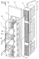
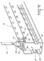
- a backplane assembly is shown comprised of a daughter board connector 2 which is substantially similar to that shown in European Publication number 0 422 785.
- the daughter board assembly 2 is comprised of a daughter board 6 having a plurality of connector housings 8 mounted thereto which are electrically connectable to header connectors 10 providing a pin field on both sides of a backplane 12. Pins extend through the back plane 12, such that a pin field is formed within the headers 10 for electrical connection with the daughter board connectors 8, and further comprise a pin field on the opposite side of the backplane 12 providing a pin field for the cable connector assembly 4.
- the cable assembly 4 is comprised of a stamped and formed mounting rail 16 positioned over the pin field formed by the pins 14, together with a plurality of connector assemblies 18.
- the connector 18 is comprised of an insulating housing shown generally at 20 having a lower mating face 22 and a rear cable receiving face 24.
- the housing 20 further comprises a side wall 26 and an opposite side wall 28.
- the housing 20 includes a notched section at 30 thereby defining a recessed surface 31 and a rib 32 generally extending along one side edge of the side wall 26.
- the opposite side includes a notched section 34 for clearance purposes as will be described herein, thereby defining a lower alignment edge 36.
- the housing 20 further includes two latch arms 38 integrally formed with the connector housing 20 and being moveable towards and away from each other, the two latch arms 38 being formed with a side seam shown at 40, and being hinged at a lower section 42.
- Each latch arm 38 includes a latching lug portion 44 for locking the connector 18 in position within the mounting rail 16.
- the latch arms 38 are moveable to an unlocked position by way of a release mechanism shown generally at 46 comprised of a mylar strip 48 which extends through apertures 50 adjacent to the free ends of the latch arms 38, such that upward movement of the mechanism 46 pulls the arms towards each other thereby moving the locking lugs 44 inwardly for releasement.
- the connector 18 is profiled as a 20 position connector, having four rows of five contacts across, and therefore the front mating face 22 has corresponding pin receiving openings for receiving the pins 14 of the backplane connector 12.
- Two ten-conductor cables 52 and 54 extend through corresponding openings 56 and 58 through the rear cable receiving face 24 for electrical connection with electrical contacts in the connector 18. It should be appreciated that the cable receiving openings 56 and 58 are offset from the center line of the connector such that it does not interfere with the operation of the mylar strip 48 which extends between the latching arms 38.
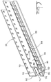
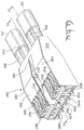
- the mounting rail 16 is shown in greater detail.
- the mounting rail 16 is in the preferred embodiment stamped and formed from a flat strip of metal material to comprise a lower mounting plate 60 and two upright vertical walls 62 and 64.
- the lower mounting plate 60 comprises mounting apertures 62 for mounting the rail 16 to the backplane 12 as shown in Figure 1.
- the lower mounting surface 60 further includes a plurality of openings at 66 ( Figure 4) which provide access for the pins 14 ( Figure 1) to extend upwardly therethrough.
- the openings 66 are symmetrically positioned along the lower mounting face 60 separated by strap portions 68, although adjacent openings 66 could be joined by removing one or more of the strap portions, for example by severing the lower plate portion 60 at 70.
- Each side wall 62 and 64 contains a plurality of apertures 72 ( Figure 3) which are profiled to receive the latching lugs 44 ( Figure 2) of the cable connector 18.
- the side wall 62 includes a stamped recess at 74 extending along the longitudinal length of the side wall 62 thereby defining an inner surface at 76.
- a plurality of slots 78 are stamped out of the side wall 62 positioned above the surface 76, whereas a plurality of ribs 80 are stamped from the side walls 62, but are not stamped free from the side wall, but rather extend in a co-planer manner with the surface 76.
- the side wall 64 includes a stamped recess 84 providing an inner surface at 86.
- a plurality of ribs 88 are stamped free of the side wall 64 and extend upwardly in a co-planar arrangement with the side wall 64, thereby defining a plurality of continuous slots at 90.
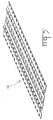
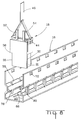
- the mounting rail 16 is stamped and formed in a flat strip and as shown in Figures 5-7, and can be taken up and stored on a reel 92, whereby the strip material shown at 16' can be dereeled and sheered into the appropriate length as shown in Figure 7.
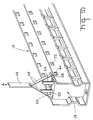
- the mounting rail 16 can be mounted to a backplane 12 as shown in Figure 1 with the pin field 14 of the header connector 10 extending therethrough and a plurality of cable connectors 18 can be interconnected to the daughter board assembly 2 via the pins 14.
- the cable connector 18 can be positioned above the mounting rail 16 with the rib 32 aligned with one of the ribs 90 and with the rib 36 aligned with the slot 78.
- the inner surfaces 76 and 86 are profiled to receive the side surfaces 31 and 35 of the connector 18 while the connector 18 is aligned with the mounting rail 16 and the pins 14 by way of the ribs 32 and 36.
- the connector 18 is shown fully inserted in the mounting rail 16 with the ribs 36 and 32 positioned in corresponding slots 78 and 90 (Figure 8). In this position, the locking lugs 44 are latched into position with the apertures 72 on the side walls of the mounting rail 16. It should be appreciated that the connector 18 is easily disconnected from the mounting rail 16 and from the backplane assembly via pulling the release mechanism 46 in the direction of arrow A which moves the latching arms 38 inwardly thereby releasing the latching lugs 44 from the corresponding apertures 72. It should be appreciated that the release mechanisms 46 provide great ease in disconnecting the cable connector 18 from the back panel.
- the mounting rail 16 can be produced easily and inexpensively yet provide all the features necessary for mounting and aligning the various connectors 18. It should be appreciated that any number of longitudinal lengths will be required housing any number of connector assemblies 18. If the mounting rail 16 were moulded from a plastic material, several different mould cavities will be required to mould the various lengths, while extruding the mounting rail for plastic material could not provide the alignment features necessary for the connector.
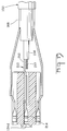
- the cable connector includes an inner housing assembly comprised of a lower housing portion 116 having a front mating face 118 having a plurality of pin receiving openings at 120.
- the connector 118 further comprises an upper cover part 122 having a plurality of pin receiving openings at 124.
- the complementary covers 116 and 122 cooperatively provide cable receiving openings through a rear face, such as at 126.
- an inner insert housing portion is shown at 130 comprising a front face 132 having pin receiving openings shown generally at 134, and terminal receiving channels such as 136 and 138 positioned on upper 40 and lower 42 surfaces thereof.
- a central channel 145 is defined between side walls 146 and 148 which provides a communication with the center pin receiving opening at 134c.
- the inner housing portion 130 is interconnected to two twinaxial cables 52' and 54' comprised of an outer insulative portion 152 having a shielded section at 154 and two twinaxial cable pairs: 156a, 156b, 156c, 156d.
- twinaxial signal conductors 156a and 156b are in alignment with the pin receiving openings 134a and 134b respectively, whereas twinaxial signal conductors 156c and 156d are in alignment with pin receiving openings 134d and 134e respectively. This leaves the center pin receiving opening 134c and the channel 145 empty.
- a shield member is shown generally at 160 comprised of upper plate portions 162 and 164 with rear connecting sections 166 and 168 in contact with the shield 154 of the twinax cables 52', 54'. It should be appreciated that this connection could be by soldering, welding, or by way of ferrule or similar clamp.
- Two contact members 168 and 170 extend forwardly from the plate portion 162 whereas two contact members 172 and 174 extend forwardly from the plate portion 164.
- the contacts 168 and 170 are defined by bifurcated contact arms, shown generally at 176 in Figure 13, which are positioned in two of the channels 136 whereas contacts 172 and 174 are positioned in the channels 136 above the pin receiving passageways 134d and 134e.
- a center ground tab 180 is stamped from a central plate section, intermediate plate sections 162 and 164, and includes an integral contact portion 182 as best shown in Figure 14.
- This contact tab portion is bent downwardly into the channel 145 and intermediate the walls 146 and 148, ( Figure 13).
- the contact portion 182 is aligned with the pin receiving opening at 134c.
- the shielding further comprises a lower shield member 190, and side plate portions 192 and 194.
- the lower shield portion 190 has integral contact members 198-206 ( Figure 13), identical to the integral contacts 168-174, the contact members being positioned in respective channels 138 ( Figure 12).
- signal contacts 210 are shown connected to the signal conductor 157, where the signal conductor is positioned in passageway 134d.
- the contact 210 contains a connecting portion 212 for contact with the signal conductor 157, and a receptacle portion 214 for contact with a mating pin 14 on the pin field shown in Figure 1.
- each passageway 134a-134d carries a terminal similar to contact 210, each separately connected to a respective conductor 156a-156a.
- the upper and lower cover parts 116 and 122 can be positioned over the inner insert housing portion 130 to encapsulate the shielded members, as shown in Figure 16.
- two separate differential pairs are fully shielded by way of the outer shield members together with the shielding contacts surrounding the signal contacts.
- the connector concept could also be used with three coaxial cables, where the signal conductors are aligned with passageways 134a, 134c, 134d; and where the upper shield has a contact similar to 180, 182 extending into cavities 134b, 134d, through channels (similar to 145) positioned above the cavities 134b, 134d.
Applications Claiming Priority (4)
| Application Number | Priority Date | Filing Date | Title |
|---|---|---|---|
| GB929210119A GB9210119D0 (en) | 1992-05-11 | 1992-05-11 | Cable backpanel interconnection |
| GB9210131 | 1992-05-11 | ||
| GB929210131A GB9210131D0 (en) | 1992-05-11 | 1992-05-11 | High frequency cable connector |
| GB9210119 | 1992-05-11 |
Publications (3)
| Publication Number | Publication Date |
|---|---|
| EP0570181A2 true EP0570181A2 (de) | 1993-11-18 |
| EP0570181A3 EP0570181A3 (en) | 1997-01-02 |
| EP0570181B1 EP0570181B1 (de) | 1999-12-08 |
Family
ID=26300861
Family Applications (1)
| Application Number | Title | Priority Date | Filing Date |
|---|---|---|---|
| EP93303601A Expired - Lifetime EP0570181B1 (de) | 1992-05-11 | 1993-05-10 | Elektrischer Verbinder für Hochfrequenz |
Country Status (6)
| Country | Link |
|---|---|
| US (2) | US5380216A (de) |
| EP (1) | EP0570181B1 (de) |
| JP (1) | JP3416191B2 (de) |
| KR (1) | KR100290219B1 (de) |
| CN (1) | CN1073296C (de) |
| DE (1) | DE69327194T2 (de) |
Cited By (18)
| Publication number | Priority date | Publication date | Assignee | Title |
|---|---|---|---|---|
| GB2284312A (en) * | 1993-11-26 | 1995-05-31 | Mecanismos Aux Ind | Modular electrical connector system |
| EP0743714A2 (de) * | 1995-05-17 | 1996-11-20 | AT&T IPM Corp. | Montieren einer Positionssicherung in einem Verbindungsblock |
| EP0836246A1 (de) * | 1996-10-12 | 1998-04-15 | Molex Incorporated | Verschlüsselungssystem für elektrische Verbinder |
| WO1998019368A1 (en) * | 1996-10-31 | 1998-05-07 | The Whitaker Corporation | Panel mount bracket for electrical connector |
| EP0860906A2 (de) * | 1997-02-22 | 1998-08-26 | Harting KGaA | Halterahmen für Steckverbindermodulen |
| EP1693929A1 (de) * | 2005-02-21 | 2006-08-23 | Tyco Electronics AMP K.K. | Kabelverbinder |
| WO2007075503A1 (en) * | 2005-12-19 | 2007-07-05 | 3M Innovative Properties Company | Boardmount header to cable connector assembly |
| US7553187B2 (en) | 2006-01-31 | 2009-06-30 | 3M Innovative Properties Company | Electrical connector assembly |
| US7651359B2 (en) | 2006-09-14 | 2010-01-26 | 3M Innovative Properties Company | Electrical connector assembly |
| US7722394B2 (en) | 2008-02-21 | 2010-05-25 | 3M Innovative Properties Company | Electrical termination device |
| US7731528B2 (en) | 2006-01-31 | 2010-06-08 | 3M Innovative Properties Company | Electrical termination device |
| CN102318143A (zh) * | 2008-12-12 | 2012-01-11 | 莫列斯公司 | 谐振调整连接器 |
| WO2015070936A1 (de) * | 2013-11-13 | 2015-05-21 | Baumüller Nürnberg GmbH | Elektromotorisches antriebssystem |
| CN106786031A (zh) * | 2017-02-21 | 2017-05-31 | 南京信息职业技术学院 | 一种多功能配电装置 |
| WO2018206048A1 (de) * | 2017-05-12 | 2018-11-15 | Harting Electric Gmbh & Co. Kg | Steckverbindermodul |
| US10418773B2 (en) | 2013-12-12 | 2019-09-17 | Harting Electric Gmbh & Co. Kg | Holding frame for a plug-type connector |
| CN111864436A (zh) * | 2020-07-06 | 2020-10-30 | 中航光电科技股份有限公司 | 一种超高速高密度高可靠连接器插针 |
| US20210090762A1 (en) * | 2018-10-11 | 2021-03-25 | International Business Machines Corporation | Hybrid cable assembly |
Families Citing this family (53)
| Publication number | Priority date | Publication date | Assignee | Title |
|---|---|---|---|---|
| US5718607A (en) * | 1996-03-01 | 1998-02-17 | Molex Incorporated | System for terminating the shield of a high speed cable |
| US5775924A (en) * | 1996-10-11 | 1998-07-07 | Molex Incorporated | Modular terminating connector with frame ground |
| US6083047A (en) * | 1997-01-16 | 2000-07-04 | Berg Technology, Inc. | Modular electrical PCB assembly connector |
| JP3147848B2 (ja) * | 1998-03-11 | 2001-03-19 | 日本電気株式会社 | コネクタ |
| US6514090B1 (en) | 1998-04-29 | 2003-02-04 | International Business Machines Corporation | Method and apparatus for high speed differential signaling, employing split pin connectors and split via technology |
| DE19853837C1 (de) * | 1998-11-23 | 2000-02-24 | Krone Ag | Abschirmeinrichtung für Anschlußleisten der Telekommunikations- und Datentechnik |
| US6171149B1 (en) | 1998-12-28 | 2001-01-09 | Berg Technology, Inc. | High speed connector and method of making same |
| US6394842B1 (en) * | 1999-04-01 | 2002-05-28 | Fujitsu Takamisawa Component Limited | Cable connecting structure |
| US6471547B1 (en) * | 1999-06-01 | 2002-10-29 | John T. Venaleck | Electrical connector for high density signal interconnections and method of making the same |
| US6217364B1 (en) | 1999-07-09 | 2001-04-17 | Molex Incorporated | Electrical connector assembly with guide pin latching system |
| US6422900B1 (en) | 1999-09-15 | 2002-07-23 | Hh Tower Group | Coaxial cable coupling device |
| US6524135B1 (en) | 1999-09-20 | 2003-02-25 | 3M Innovative Properties Company | Controlled impedance cable connector |
| US6203369B1 (en) | 1999-10-25 | 2001-03-20 | 3M Innovative Properties Company | High frequency cable connector having low self-inductance ground return paths |
| US6283792B1 (en) * | 2000-07-11 | 2001-09-04 | Bernard R. Tolmie | Extruded metallic electrical connector assembly and method of producing same |
| US6504379B1 (en) * | 2000-11-16 | 2003-01-07 | Fluke Networks, Inc. | Cable assembly |
| US6413103B1 (en) | 2000-11-28 | 2002-07-02 | Apple Computer, Inc. | Method and apparatus for grounding microcoaxial cables inside a portable computing device |
| US6979202B2 (en) * | 2001-01-12 | 2005-12-27 | Litton Systems, Inc. | High-speed electrical connector |
| US6843657B2 (en) | 2001-01-12 | 2005-01-18 | Litton Systems Inc. | High speed, high density interconnect system for differential and single-ended transmission applications |
| US6910897B2 (en) | 2001-01-12 | 2005-06-28 | Litton Systems, Inc. | Interconnection system |
| CN1228891C (zh) | 2001-01-29 | 2005-11-23 | 蒂科电子公司 | 用于绞合对电缆的高密度插头接插件 |
| CN1237668C (zh) | 2001-01-29 | 2006-01-18 | 蒂科电子公司 | 高密度插座接插件 |
| US6612857B2 (en) | 2001-07-05 | 2003-09-02 | Bernard R. Tolmie | Electrical connector system and method having optical and/or cooling capability |
| JP3564556B2 (ja) * | 2001-10-02 | 2004-09-15 | 日本航空電子工業株式会社 | コネクタ |
| US6623307B2 (en) * | 2001-11-08 | 2003-09-23 | Hon Hai Precision Ind. Co., Ltd. | High frequency modular jack connector |
| US6821146B2 (en) * | 2002-01-07 | 2004-11-23 | Bernard R. Tolmie | Hybrid connector system and method |
| JP2003297482A (ja) | 2002-02-01 | 2003-10-17 | Japan Aviation Electronics Industry Ltd | プルタブを用いたロック解除機構及びコネクタ |
| US6971892B2 (en) * | 2002-06-13 | 2005-12-06 | Hewlett-Packard Development Company, L.P. | Method and device for protecting pins of a pin connector |
| WO2005053102A2 (en) * | 2003-11-21 | 2005-06-09 | Ohio Associated Enterprises Llc | Cable assembly and method of making |
| TWM251379U (en) * | 2004-02-11 | 2004-11-21 | Comax Technology Inc | Grounding structure of electrical connector |
| US7513797B2 (en) | 2004-02-27 | 2009-04-07 | 3M Innovative Properties Company | Connector apparatus |
| US7394170B2 (en) * | 2005-04-19 | 2008-07-01 | Sanmina-Sci Corporation | Reconfigurable backplane power distribution |
| US7689089B2 (en) * | 2006-10-11 | 2010-03-30 | Panduit Corp. | Release latch for pre-terminated cassette |
| US7484989B2 (en) * | 2006-11-29 | 2009-02-03 | Ohio Associated Enterprises, Llc | Low friction cable assembly latch |
| JP5120184B2 (ja) * | 2008-09-30 | 2013-01-16 | 富士通株式会社 | 基板固定部材、およびこれを用いた電子装置 |
| US7789703B2 (en) * | 2008-10-21 | 2010-09-07 | Tyco Electronics Corporation | Connector having a shield electrically coupled to a cable shield |
| JP2012531015A (ja) | 2009-06-19 | 2012-12-06 | スリーエム イノベイティブ プロパティズ カンパニー | 遮蔽された電気ケーブル |
| US9685259B2 (en) | 2009-06-19 | 2017-06-20 | 3M Innovative Properties Company | Shielded electrical cable |
| US8475177B2 (en) * | 2010-01-20 | 2013-07-02 | Ohio Associated Enterprises, Llc | Backplane cable interconnection |
| EP3046115B1 (de) | 2010-08-31 | 2019-07-24 | 3M Innovative Properties Company | Hochdichtes abgeschirmtes elektrokabel und andere abgeschirmte kabel, systeme und verfahren |
| WO2012030367A1 (en) | 2010-08-31 | 2012-03-08 | 3M Innovative Properties Company | Shielded electrical cable in twinaxial configuration |
| US10147522B2 (en) | 2010-08-31 | 2018-12-04 | 3M Innovative Properties Company | Electrical characteristics of shielded electrical cables |
| BR112013003296A2 (pt) | 2010-08-31 | 2016-06-07 | 3M Innovatie Properties Company | cabo elétrico blindado e montagem de cabo |
| JP2013521611A (ja) | 2010-08-31 | 2013-06-10 | スリーエム イノベイティブ プロパティズ カンパニー | 誘導性間隔のある遮蔽電気ケーブル |
| CN102870169B (zh) | 2010-08-31 | 2016-02-17 | 3M创新有限公司 | 屏蔽电缆的连接器布置方式 |
| CN103119661B (zh) | 2010-09-23 | 2015-08-19 | 3M创新有限公司 | 屏蔽电缆 |
| EP2541696A1 (de) | 2011-06-29 | 2013-01-02 | Tyco Electronics Belgium EC BVBA | Elektrischer Steckverbinder |
| JP2013225475A (ja) * | 2012-03-19 | 2013-10-31 | Fujitsu Component Ltd | コンタクト、コネクタ、及びその製造方法 |
| US8845368B1 (en) * | 2012-08-31 | 2014-09-30 | Amazon Technologies, Inc. | Electrical connectors |
| CN104064893B (zh) * | 2014-06-06 | 2016-06-29 | 华为技术有限公司 | 一种背板及通讯设备 |
| JP6179475B2 (ja) * | 2014-07-30 | 2017-08-16 | 株式会社オートネットワーク技術研究所 | コネクタユニット |
| JP2016091734A (ja) * | 2014-10-31 | 2016-05-23 | 日立金属株式会社 | 通信モジュール |
| JP2016100426A (ja) * | 2014-11-20 | 2016-05-30 | 日立金属株式会社 | 通信モジュール |
| CN113540906B (zh) * | 2021-07-14 | 2022-07-22 | 重庆中车四方所科技有限公司 | 一种连接器自动布线装置 |
Citations (13)
| Publication number | Priority date | Publication date | Assignee | Title |
|---|---|---|---|---|
| US3576520A (en) * | 1969-04-11 | 1971-04-27 | Amp Inc | Mounting means for terminal junction modules |
| FR2123622A5 (de) * | 1971-01-25 | 1972-09-15 | Pyle National Co | |
| DE2242258B1 (de) * | 1972-08-28 | 1973-11-08 | Siemens Ag, 1000 Berlin U. 8000 Muenchen | Zangenartige Vorrichtung zum Ab ziehen von Bauteilen |
| US4032209A (en) * | 1976-01-15 | 1977-06-28 | Appleton Electric Company | Multiple socket assembly for electrical components |
| DE2801427A1 (de) * | 1977-01-14 | 1978-07-20 | Bunker Ramo | Haltesicherung fuer eine elektrische verbindung |
| DE2736079A1 (de) * | 1977-08-10 | 1979-02-22 | Air Lb Gmbh | Einrastbare reihenklemme oder anschlussmoduln sowie traegerschiene hierfuer |
| FR2489609A1 (fr) * | 1980-08-26 | 1982-03-05 | Lb Air | Module de raccordement de conducteurs electriques a connecteurs amovibles |
| DE3426783A1 (de) * | 1984-07-20 | 1986-01-30 | Robert Bosch Gmbh, 7000 Stuttgart | Abziehvorrichtung zum entfernen elektrischer geraete |
| US4984992A (en) * | 1989-11-01 | 1991-01-15 | Amp Incorporated | Cable connector with a low inductance path |
| US5057038A (en) * | 1990-09-24 | 1991-10-15 | Molex Incorporated | Shielded electrical connection |
| FR2661048A1 (fr) * | 1990-04-17 | 1991-10-18 | Amp Inc | Systeme pour retenir de facon amovible plusieurs modules en une rangee sur un panneau et outil a utiliser avec un tel systeme. |
| EP0458483A1 (de) * | 1990-05-09 | 1991-11-27 | THOMAS & BETTS CORPORATION | Verbesserungen in bezug auf Verbinder |
| EP0442643B1 (de) * | 1990-02-13 | 1995-09-06 | W.L. GORE & ASSOCIATES (UK) LTD | Abgeschirmter Verbinder |
Family Cites Families (16)
| Publication number | Priority date | Publication date | Assignee | Title |
|---|---|---|---|---|
| US4448471A (en) * | 1982-05-20 | 1984-05-15 | Amp Incorporated | Polarized locking latch cover for an electrical connector |
| DE3318137C2 (de) * | 1983-05-18 | 1986-07-31 | Erni Elektroapparate Gmbh, 7321 Adelberg | Mehrpolige elektrische Steckvorrichtung |
| US4494816A (en) * | 1983-07-27 | 1985-01-22 | At&T Bell Laboratories | Coaxial cable connector |
| US4681387A (en) * | 1986-11-21 | 1987-07-21 | The United States Of America As Represented By The Secretary Of The Army | Latch connector |
| US4893263A (en) * | 1987-02-12 | 1990-01-09 | Compaq Computer Corporation | Support apparatus for portable computer expansion unit |
| DE3938964A1 (de) * | 1988-11-24 | 1990-05-31 | Yazaki Corp | Mehrfachstufenverbinder |
| DE3841083C1 (de) * | 1988-12-02 | 1990-02-01 | Krone Ag, 1000 Berlin, De | |
| NL8901438A (nl) * | 1989-06-06 | 1991-01-02 | Du Pont Nederland | Connector. |
| US5066236A (en) * | 1989-10-10 | 1991-11-19 | Amp Incorporated | Impedance matched backplane connector |
| US5026304A (en) * | 1989-12-22 | 1991-06-25 | Amp Incorporated | Connector and connector assembly having improved terminal insertion feature |
| US5197893A (en) * | 1990-03-14 | 1993-03-30 | Burndy Corporation | Connector assembly for printed circuit boards |
| US5090920A (en) * | 1990-04-17 | 1992-02-25 | Amp Incorporated | Module retention/ejection system |
| JPH0454165U (de) * | 1990-09-17 | 1992-05-08 | ||
| SE466126B (sv) * | 1990-12-21 | 1991-12-16 | Vemako Ab | Flerpoligt skaermat kontaktdon med gemensam jord |
| US5171161A (en) * | 1991-05-09 | 1992-12-15 | Molex Incorporated | Electrical connector assemblies |
| US5199902A (en) * | 1991-12-23 | 1993-04-06 | Gte Products Corporation | Connector device |
-
1993
- 1993-04-21 US US08/052,054 patent/US5380216A/en not_active Expired - Fee Related
- 1993-05-10 DE DE69327194T patent/DE69327194T2/de not_active Expired - Fee Related
- 1993-05-10 KR KR1019930007946A patent/KR100290219B1/ko not_active IP Right Cessation
- 1993-05-10 EP EP93303601A patent/EP0570181B1/de not_active Expired - Lifetime
- 1993-05-11 JP JP10896893A patent/JP3416191B2/ja not_active Expired - Fee Related
- 1993-05-11 CN CN93105663A patent/CN1073296C/zh not_active Expired - Fee Related
-
1994
- 1994-07-08 US US08/272,890 patent/US5460533A/en not_active Expired - Fee Related
Patent Citations (13)
| Publication number | Priority date | Publication date | Assignee | Title |
|---|---|---|---|---|
| US3576520A (en) * | 1969-04-11 | 1971-04-27 | Amp Inc | Mounting means for terminal junction modules |
| FR2123622A5 (de) * | 1971-01-25 | 1972-09-15 | Pyle National Co | |
| DE2242258B1 (de) * | 1972-08-28 | 1973-11-08 | Siemens Ag, 1000 Berlin U. 8000 Muenchen | Zangenartige Vorrichtung zum Ab ziehen von Bauteilen |
| US4032209A (en) * | 1976-01-15 | 1977-06-28 | Appleton Electric Company | Multiple socket assembly for electrical components |
| DE2801427A1 (de) * | 1977-01-14 | 1978-07-20 | Bunker Ramo | Haltesicherung fuer eine elektrische verbindung |
| DE2736079A1 (de) * | 1977-08-10 | 1979-02-22 | Air Lb Gmbh | Einrastbare reihenklemme oder anschlussmoduln sowie traegerschiene hierfuer |
| FR2489609A1 (fr) * | 1980-08-26 | 1982-03-05 | Lb Air | Module de raccordement de conducteurs electriques a connecteurs amovibles |
| DE3426783A1 (de) * | 1984-07-20 | 1986-01-30 | Robert Bosch Gmbh, 7000 Stuttgart | Abziehvorrichtung zum entfernen elektrischer geraete |
| US4984992A (en) * | 1989-11-01 | 1991-01-15 | Amp Incorporated | Cable connector with a low inductance path |
| EP0442643B1 (de) * | 1990-02-13 | 1995-09-06 | W.L. GORE & ASSOCIATES (UK) LTD | Abgeschirmter Verbinder |
| FR2661048A1 (fr) * | 1990-04-17 | 1991-10-18 | Amp Inc | Systeme pour retenir de facon amovible plusieurs modules en une rangee sur un panneau et outil a utiliser avec un tel systeme. |
| EP0458483A1 (de) * | 1990-05-09 | 1991-11-27 | THOMAS & BETTS CORPORATION | Verbesserungen in bezug auf Verbinder |
| US5057038A (en) * | 1990-09-24 | 1991-10-15 | Molex Incorporated | Shielded electrical connection |
Cited By (27)
| Publication number | Priority date | Publication date | Assignee | Title |
|---|---|---|---|---|
| GB2284312A (en) * | 1993-11-26 | 1995-05-31 | Mecanismos Aux Ind | Modular electrical connector system |
| GB2284312B (en) * | 1993-11-26 | 1997-11-19 | Mecanismos Aux Ind | Modular connector system |
| EP0743714A2 (de) * | 1995-05-17 | 1996-11-20 | AT&T IPM Corp. | Montieren einer Positionssicherung in einem Verbindungsblock |
| EP0743714A3 (de) * | 1995-05-17 | 1997-12-10 | AT&T IPM Corp. | Montieren einer Positionssicherung in einem Verbindungsblock |
| EP0836246A1 (de) * | 1996-10-12 | 1998-04-15 | Molex Incorporated | Verschlüsselungssystem für elektrische Verbinder |
| WO1998019368A1 (en) * | 1996-10-31 | 1998-05-07 | The Whitaker Corporation | Panel mount bracket for electrical connector |
| EP0860906A2 (de) * | 1997-02-22 | 1998-08-26 | Harting KGaA | Halterahmen für Steckverbindermodulen |
| EP0860906A3 (de) * | 1997-02-22 | 2000-03-08 | Harting KGaA | Halterahmen für Steckverbindermodulen |
| EP1693929A1 (de) * | 2005-02-21 | 2006-08-23 | Tyco Electronics AMP K.K. | Kabelverbinder |
| WO2007075503A1 (en) * | 2005-12-19 | 2007-07-05 | 3M Innovative Properties Company | Boardmount header to cable connector assembly |
| US7553187B2 (en) | 2006-01-31 | 2009-06-30 | 3M Innovative Properties Company | Electrical connector assembly |
| US7762847B2 (en) | 2006-01-31 | 2010-07-27 | 3M Innovative Properties Company | Electrical connector assembly |
| US7731528B2 (en) | 2006-01-31 | 2010-06-08 | 3M Innovative Properties Company | Electrical termination device |
| US7651359B2 (en) | 2006-09-14 | 2010-01-26 | 3M Innovative Properties Company | Electrical connector assembly |
| US7722394B2 (en) | 2008-02-21 | 2010-05-25 | 3M Innovative Properties Company | Electrical termination device |
| CN102318143A (zh) * | 2008-12-12 | 2012-01-11 | 莫列斯公司 | 谐振调整连接器 |
| CN102318143B (zh) * | 2008-12-12 | 2015-03-11 | 莫列斯公司 | 谐振调整连接器 |
| WO2015070936A1 (de) * | 2013-11-13 | 2015-05-21 | Baumüller Nürnberg GmbH | Elektromotorisches antriebssystem |
| US10103599B2 (en) | 2013-11-13 | 2018-10-16 | Baumueller Nuernberg Gmbh | Electromotive drive system electronic housing with plug connections for DC voltage supplies, field busses and digital inputs and outputs |
| US10418773B2 (en) | 2013-12-12 | 2019-09-17 | Harting Electric Gmbh & Co. Kg | Holding frame for a plug-type connector |
| US10424892B2 (en) | 2013-12-12 | 2019-09-24 | Harting Electric Gmbh & Co. Kg | Holding frame for a plug-type connector |
| US10554007B2 (en) | 2013-12-12 | 2020-02-04 | Harting Electric Gmbh & Co. Kg | Holding frame for a plug-type connector |
| CN106786031A (zh) * | 2017-02-21 | 2017-05-31 | 南京信息职业技术学院 | 一种多功能配电装置 |
| WO2018206048A1 (de) * | 2017-05-12 | 2018-11-15 | Harting Electric Gmbh & Co. Kg | Steckverbindermodul |
| US20210090762A1 (en) * | 2018-10-11 | 2021-03-25 | International Business Machines Corporation | Hybrid cable assembly |
| US11676741B2 (en) * | 2018-10-11 | 2023-06-13 | International Business Machines Corporation | Hybrid cable assembly |
| CN111864436A (zh) * | 2020-07-06 | 2020-10-30 | 中航光电科技股份有限公司 | 一种超高速高密度高可靠连接器插针 |
Also Published As
| Publication number | Publication date |
|---|---|
| CN1078575A (zh) | 1993-11-17 |
| JP3416191B2 (ja) | 2003-06-16 |
| DE69327194D1 (de) | 2000-01-13 |
| US5460533A (en) | 1995-10-24 |
| KR930024228A (ko) | 1993-12-22 |
| EP0570181B1 (de) | 1999-12-08 |
| EP0570181A3 (en) | 1997-01-02 |
| JPH0652924A (ja) | 1994-02-25 |
| CN1073296C (zh) | 2001-10-17 |
| DE69327194T2 (de) | 2004-09-02 |
| KR100290219B1 (ko) | 2001-05-15 |
| US5380216A (en) | 1995-01-10 |
Similar Documents
| Publication | Publication Date | Title |
|---|---|---|
| US5380216A (en) | Cable backpanel interconnection | |
| US5445538A (en) | Electrical connector strain relief | |
| US4711507A (en) | Electrical connector and latching apparatus therefor | |
| US4725249A (en) | Connector assembly | |
| US4619494A (en) | Shielded electrical connector | |
| US5096442A (en) | Compact electrical connector | |
| US4682836A (en) | Electrical connector and cable termination apparatus therefor | |
| US4491381A (en) | Electrical panelboard connector | |
| US6210230B1 (en) | Cable connector | |
| US5372513A (en) | Electrical connector with cable shield ground clip | |
| EP0873581B1 (de) | Elektrische steckvorrichtung | |
| US5538440A (en) | Electrical connector having a conductor holding block | |
| GB2232827A (en) | Electrical connector system for coaxial cable | |
| US5681180A (en) | Conductor holding block for an electrical connector | |
| US4372634A (en) | Tilt latch zero insertion force connector assembly | |
| CA1128619A (en) | Circuit board interconnection system | |
| EP0634816B1 (de) | Vertikal ausgerichtete elektrische abgeschirmte Verbinderbauteile | |
| EP0653804B1 (de) | Elektrischer Verbinder mit Leiterhalterung | |
| EP0565329A2 (de) | Abgeschirmter elektrischer Verbinder | |
| EP0454278B1 (de) | Elektrischer Verbinder verwendet für Leiterplatte |
Legal Events
| Date | Code | Title | Description |
|---|---|---|---|
| PUAI | Public reference made under article 153(3) epc to a published international application that has entered the european phase |
Free format text: ORIGINAL CODE: 0009012 |
|
| AK | Designated contracting states |
Kind code of ref document: A2 Designated state(s): DE ES FR GB NL SE |
|
| PUAL | Search report despatched |
Free format text: ORIGINAL CODE: 0009013 |
|
| AK | Designated contracting states |
Kind code of ref document: A3 Designated state(s): DE ES FR GB NL SE |
|
| 17P | Request for examination filed |
Effective date: 19970627 |
|
| 17Q | First examination report despatched |
Effective date: 19970903 |
|
| GRAG | Despatch of communication of intention to grant |
Free format text: ORIGINAL CODE: EPIDOS AGRA |
|
| GRAG | Despatch of communication of intention to grant |
Free format text: ORIGINAL CODE: EPIDOS AGRA |
|
| GRAG | Despatch of communication of intention to grant |
Free format text: ORIGINAL CODE: EPIDOS AGRA |
|
| GRAH | Despatch of communication of intention to grant a patent |
Free format text: ORIGINAL CODE: EPIDOS IGRA |
|
| GRAH | Despatch of communication of intention to grant a patent |
Free format text: ORIGINAL CODE: EPIDOS IGRA |
|
| RBV | Designated contracting states (corrected) |
Designated state(s): DE FR GB NL |
|
| GRAA | (expected) grant |
Free format text: ORIGINAL CODE: 0009210 |
|
| AK | Designated contracting states |
Kind code of ref document: B1 Designated state(s): DE FR GB NL |
|
| REF | Corresponds to: |
Ref document number: 69327194 Country of ref document: DE Date of ref document: 20000113 |
|
| ITF | It: translation for a ep patent filed |
Owner name: BUZZI, NOTARO&ANTONIELLI D'OULX |
|
| ET | Fr: translation filed | ||
| NLV1 | Nl: lapsed or annulled due to failure to fulfill the requirements of art. 29p and 29m of the patents act | ||
| NLXE | Nl: other communications concerning ep-patents (part 3 heading xe) |
Free format text: A REQUEST FOR RESTORATION TO THE PRIOR STATE (ART. 23 OF THE PATENTS ACT 1995) HAS BEEN FILED ON 11.04.2000. |
|
| PLBE | No opposition filed within time limit |
Free format text: ORIGINAL CODE: 0009261 |
|
| STAA | Information on the status of an ep patent application or granted ep patent |
Free format text: STATUS: NO OPPOSITION FILED WITHIN TIME LIMIT |
|
| 26N | No opposition filed | ||
| NLXE | Nl: other communications concerning ep-patents (part 3 heading xe) |
Free format text: THE REQUEST FOR RESTORATION TO THE PRIOR STATE AS PROVIDED FOR IN ART. 23 OF THE PATENTS ACT. 1995 (SEE PUBLICATION IN HEADING XE OF THE PATENT BULLETIN OF 05.06.2000/06) HAS BEEN GRANTED; THE RESTORATION OF THE PATENT HAS BEEN ENTERED IN THE PATENT REGISTER. |
|
| REG | Reference to a national code |
Ref country code: GB Ref legal event code: IF02 |
|
| PGFP | Annual fee paid to national office [announced via postgrant information from national office to epo] |
Ref country code: NL Payment date: 20020325 Year of fee payment: 10 |
|
| PG25 | Lapsed in a contracting state [announced via postgrant information from national office to epo] |
Ref country code: NL Free format text: LAPSE BECAUSE OF NON-PAYMENT OF DUE FEES Effective date: 20031201 |
|
| NLV4 | Nl: lapsed or anulled due to non-payment of the annual fee |
Effective date: 20031201 |
|
| PGFP | Annual fee paid to national office [announced via postgrant information from national office to epo] |
Ref country code: GB Payment date: 20040406 Year of fee payment: 12 |
|
| PGFP | Annual fee paid to national office [announced via postgrant information from national office to epo] |
Ref country code: FR Payment date: 20040503 Year of fee payment: 12 |
|
| PGFP | Annual fee paid to national office [announced via postgrant information from national office to epo] |
Ref country code: DE Payment date: 20040528 Year of fee payment: 12 |
|
| PG25 | Lapsed in a contracting state [announced via postgrant information from national office to epo] |
Ref country code: GB Free format text: LAPSE BECAUSE OF NON-PAYMENT OF DUE FEES Effective date: 20050510 |
|
| PG25 | Lapsed in a contracting state [announced via postgrant information from national office to epo] |
Ref country code: DE Free format text: LAPSE BECAUSE OF NON-PAYMENT OF DUE FEES Effective date: 20051201 |
|
| GBPC | Gb: european patent ceased through non-payment of renewal fee |
Effective date: 20050510 |
|
| PG25 | Lapsed in a contracting state [announced via postgrant information from national office to epo] |
Ref country code: FR Free format text: LAPSE BECAUSE OF NON-PAYMENT OF DUE FEES Effective date: 20060131 |
|
| REG | Reference to a national code |
Ref country code: FR Ref legal event code: ST Effective date: 20060131 |