EP0569302B1 - Befestigungsschnalle für den Kinnriemen eines Schutzhelms - Google Patents
Befestigungsschnalle für den Kinnriemen eines Schutzhelms Download PDFInfo
- Publication number
- EP0569302B1 EP0569302B1 EP93420161A EP93420161A EP0569302B1 EP 0569302 B1 EP0569302 B1 EP 0569302B1 EP 93420161 A EP93420161 A EP 93420161A EP 93420161 A EP93420161 A EP 93420161A EP 0569302 B1 EP0569302 B1 EP 0569302B1
- Authority
- EP
- European Patent Office
- Prior art keywords
- tab
- slot
- fixing loop
- compartment
- loop according
- Prior art date
- Legal status (The legal status is an assumption and is not a legal conclusion. Google has not performed a legal analysis and makes no representation as to the accuracy of the status listed.)
- Expired - Lifetime
Links
- 230000001681 protective effect Effects 0.000 title 1
- 238000005192 partition Methods 0.000 claims description 13
- 238000003780 insertion Methods 0.000 claims description 6
- 230000037431 insertion Effects 0.000 claims description 6
- 230000000694 effects Effects 0.000 claims description 5
- 125000006850 spacer group Chemical group 0.000 claims description 4
- 238000000465 moulding Methods 0.000 claims description 2
- 238000000926 separation method Methods 0.000 description 2
- 230000001154 acute effect Effects 0.000 description 1
Images




Classifications
-
- A—HUMAN NECESSITIES
- A42—HEADWEAR
- A42B—HATS; HEAD COVERINGS
- A42B3/00—Helmets; Helmet covers ; Other protective head coverings
- A42B3/04—Parts, details or accessories of helmets
- A42B3/08—Chin straps or similar retention devices
-
- A—HUMAN NECESSITIES
- A44—HABERDASHERY; JEWELLERY
- A44B—BUTTONS, PINS, BUCKLES, SLIDE FASTENERS, OR THE LIKE
- A44B11/00—Buckles; Similar fasteners for interconnecting straps or the like, e.g. for safety belts
- A44B11/25—Buckles; Similar fasteners for interconnecting straps or the like, e.g. for safety belts with two or more separable parts
- A44B11/26—Buckles; Similar fasteners for interconnecting straps or the like, e.g. for safety belts with two or more separable parts with push-button fastenings
- A44B11/263—Buckles; Similar fasteners for interconnecting straps or the like, e.g. for safety belts with two or more separable parts with push-button fastenings with a push-button acting perpendicularly to the main plane of the buckle
-
- Y—GENERAL TAGGING OF NEW TECHNOLOGICAL DEVELOPMENTS; GENERAL TAGGING OF CROSS-SECTIONAL TECHNOLOGIES SPANNING OVER SEVERAL SECTIONS OF THE IPC; TECHNICAL SUBJECTS COVERED BY FORMER USPC CROSS-REFERENCE ART COLLECTIONS [XRACs] AND DIGESTS
- Y10—TECHNICAL SUBJECTS COVERED BY FORMER USPC
- Y10T—TECHNICAL SUBJECTS COVERED BY FORMER US CLASSIFICATION
- Y10T24/00—Buckles, buttons, clasps, etc.
- Y10T24/40—Buckles
- Y10T24/4088—One-piece
- Y10T24/4093—Looped strap
-
- Y—GENERAL TAGGING OF NEW TECHNOLOGICAL DEVELOPMENTS; GENERAL TAGGING OF CROSS-SECTIONAL TECHNOLOGIES SPANNING OVER SEVERAL SECTIONS OF THE IPC; TECHNICAL SUBJECTS COVERED BY FORMER USPC CROSS-REFERENCE ART COLLECTIONS [XRACs] AND DIGESTS
- Y10—TECHNICAL SUBJECTS COVERED BY FORMER USPC
- Y10T—TECHNICAL SUBJECTS COVERED BY FORMER US CLASSIFICATION
- Y10T24/00—Buckles, buttons, clasps, etc.
- Y10T24/45—Separable-fastener or required component thereof [e.g., projection and cavity to complete interlock]
- Y10T24/45225—Separable-fastener or required component thereof [e.g., projection and cavity to complete interlock] including member having distinct formations and mating member selectively interlocking therewith
- Y10T24/45471—Projection having movable connection between components thereof or variable configuration
- Y10T24/45524—Projection having movable connection between components thereof or variable configuration including resiliently biased projection component or surface segment
- Y10T24/45529—Requiring manual force applied against bias to interlock or disengage
- Y10T24/45534—Requiring manual force applied against bias to interlock or disengage having connected leading edge and separated trailing arms
-
- Y—GENERAL TAGGING OF NEW TECHNOLOGICAL DEVELOPMENTS; GENERAL TAGGING OF CROSS-SECTIONAL TECHNOLOGIES SPANNING OVER SEVERAL SECTIONS OF THE IPC; TECHNICAL SUBJECTS COVERED BY FORMER USPC CROSS-REFERENCE ART COLLECTIONS [XRACs] AND DIGESTS
- Y10—TECHNICAL SUBJECTS COVERED BY FORMER USPC
- Y10T—TECHNICAL SUBJECTS COVERED BY FORMER US CLASSIFICATION
- Y10T24/00—Buckles, buttons, clasps, etc.
- Y10T24/47—Strap-end-attaching devices
- Y10T24/4736—Buckle connected
Definitions
- the invention relates to a fixing loop, in particular for a chin strap of a safety helmet, comprising a male latching means intended to fit into a female retaining means to form a mechanical connection with positive locking, the female retaining means being arranged as a hollow button, and the male latching means comprising a tongue with locking pin capable of being inserted into the hollow button through a first passage slot.
- Document DE-U-88 16545 relates to a buckle of the kind mentioned, having a female retaining means equipped with two protuberances forming a V for the attachment of two straps.
- the size of such a loop is important.
- Document FR-A 2665 340 describes a chin strap loop, in which the female element has a general V shape comprising a triangular middle part, and two end parts. Each end part has grooves for hooking a strand of strap. The middle part is equipped with a recess cooperating with the button for retaining the male element.
- V-shaped loop structure imposes significant bulk, and requires the use of three strands of strap, each strand being adjustable in length. Unlocking the mechanical snap-in connection of the two male and female elements must be carried out by means of the user's two hands, which can be troublesome in certain situations.
- a first object of the invention consists in producing a fixing loop for chinstrap with reduced bulk, and for simplified use for the locking and unlocking operations.
- a second object of the invention consists in making a chin strap loop using two strands of strap.
- the second compartment is divided into two elementary adjacent chambers by a wall inclined relative to the median plane of symmetry, said wall being substantially perpendicular to the partition separating the two staged compartments, and extending from one end of the second slot up to a spacer for separating a third and a fourth slots respectively in communication with the first and second chambers.
- the tongue locking lug is elastic and comprises a catch notch cooperating with a fixed stop of the hollow button when the lug moves towards the active position in the orifice of the second surface when the tongue arrives. at the end of the insertion stroke in the first compartment.
- the buckle is unlocked by a manual pushing action on the lug to move it against the elastic force towards an inactive position so as to free the notch from the effect of locking of the stop.
- the unlocking action is thus carried out by means of one hand.
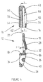
- a fixing loop 10 used in particular for a chin strap of a safety helmet, comprises a latching means 12 male intended to fit through a first slot 14 for passage in a retaining means 16 female to form a positive locking mechanical connection.
- the male latching means 12 comprises a substantially flat tongue 18 having a rounded front edge 20 delimited by two opposite edges 22, 24 extending parallel to the longitudinal interlocking direction indicated by the arrow F (FIG. 3).
- a U-shaped groove 26 is cut in the tongue 18 so as to constitute an elastic locking lug 28 mounted with limited pivoting around a fictitious transverse axis 30 and perpendicular to the longitudinal direction of fitting F.
- the free end of the lug 28 is provided with a hooking notch 32, and the elasticity effect urges the lug 28 projecting from the upper surface of the tongue 18.
- the tongue 18 of the male latching means 12 is secured opposite the edge 20, to a gripping base 34 provided with two grooves 36, 38 parallel to the imaginary axis 30 and spaced by a crosspiece 40, allowing passage intersecting and adjusting the length of a first chin strap 42 ( Figure 10).
- the female retaining means 16 is arranged in a hollow button of semi-circular shape, having a flat bottom 44, and a first front surface 46 substantially rectilinear and perpendicular to the bottom 44.
- a second upper surface 48 of the button is slightly rounded and has a orifice 50 of shape combined with that of the locking pin 28.
- the edge 52 of the orifice 50, located in the vicinity of the front surface 46, is provided with a stop 54 capable of cooperating with the catch 32 for hooking the lug 28 in the locked position of the two elements 12, 16 of loop 10 (see Figure 2).
- the internal space of the hollow button is divided by a partition 56 intermediate in a first and a second compartments 58, 60 stepped.
- the partition 56 of separation extends horizontally in a direction parallel to the bottom 44 to the front surface 46 to delimit the first slot 14 for access to the upper compartment 58, and a second slot 62 associated with the lower compartment 60, the latter being arranged between the bottom 44 and the partition 56.
- the two slots 14, 62 are parallel and superimposed in the height direction.
- the bottom 44 is connected to the second upper convex surface 48 of the button by a third semi-cylindrical lateral surface 64 equipped with a third and a fourth slots 66, 68 coplanar with the second slot 62.
- the lower compartment 60 of the retaining means 16 is itself subdivided by a vertical wall 70 into two adjacent chambers 72, 74 allowing the V-crisscrossing of a second strap 76 or chin strap (FIG. 10).
- the wall 70 is inclined at an acute angle A relative to the median plane of symmetry, extending continuously from the right end of the second slot 62 to a spacer 78 for separating the third and fourth slots 66, 68 ( Figure 7).
- the bottom 44 is pierced by a fifth slot 80 for access to the chamber 74, said slot 80 extending in the vicinity of the wall 70 and along the same inclined direction.
- the wall 82 of the bottom 44 delimiting the second slot 62 for access to the chamber 72 is slightly recessed with respect to the partition 56.
- the two latching and retaining means 12, 16 are produced by molding a plastic material having high mechanical strength.
- the gripping base 34 of the latching means 12 has a lower shoulder 84 and an upper stop 86 capable of coming into engagement against the first front surface 46 at the end of the insertion stroke of the male latching means 12 in the means 16 female retainer.
- the thickness of the three slots 62, 66, 68 of the lower compartment 60 is slightly greater than that of the strap 76.
- the female retaining means 16 is connected to one of the sides of the helmet (not shown) by the two strands of the second strap 76.
- the latter is previously placed in the two chambers 72, 74 of the lower compartment 60 of the button hollow.
- the end of the strap 76 is first introduced from the rear into the chamber 72 through the third slot 66 (according to the arrow 6 indicated in FIG. 3), then comes out at the front through the second slot 62, followed by total folding 180 degrees under the outer face of the bottom 44.
- the strap 76 is then reintroduced into the adjacent chamber 74 through the fifth slot 80 from the bottom 44, then out of said chamber 74 through the fourth slot 68 (see FIG. 11).
- the entry and exit of the second strap 76 take place on the side of the third lateral surface 64, and the shape of the V is ensured by multidirectional folding of the strap inside the hollow button.
- the first strap 42 is also placed in the two grooves 36, 38 of the base 34 for gripping the male latching means 12.
- the adjustment of the useful length of the strap 42 can be adjusted according to the morphology of the user.
- the closure of the loop 10 is obtained by the insertion according to arrow F (FIG. 3) of the tongue 18 of the male latching means 12 in the upper compartment 58 of the female retaining means 16.
- the height of the upper compartment 58 is slightly greater than the thickness of the tongue 18, and the latter has a shape combined with the longitudinal section of the compartment 58.
- the catch 32 for hooking the lug 28 comes into contact with the stop 54 of the edge 52, preventing any withdrawal of the male latching means 12, which is locked inside the upper compartment 58.
- the interval separating the wall 82 from the shoulder 84 in the locked position of the loop 10 allows the passage of the strap 76 at the level of the second slot 62.
- the unlocking of the loop 10 is operated by a manual pushing action on the lug 28 (see arrow F2 in FIG. 2), which is moved against the elastic force towards the inactive position, releasing the notch 32 from the the locking effect of the stop 54.
- the tongue 18 can then be removed from the upper compartment 58 to ensure the physical separation of the two means 12, 16 from the fixing loop 10.
- the mechanical connection by snap-fastening of the two means 12, 16 of the loop 10, and the V-intersection of the second strap 76 take place in two separate compartments 58, 60 stepped inside the hollow button of the retaining means 16 female.
- the fixing loop 10 of the chin strap therefore has a reduced bulk and improves the comfort and use of the user.
Landscapes
- Helmets And Other Head Coverings (AREA)
- Buckles (AREA)
- Emergency Lowering Means (AREA)
- Purses, Travelling Bags, Baskets, Or Suitcases (AREA)
Claims (10)
- Befestigungsschnalle, insbesondere für einen Kinnriemen eines Schutzhelms, mit einem Einrastmittel (12), das in ein Rückhaltmittel (16) eingefügt werden kann, um eine positive mechanische Verriegelungsvorrichtung zu bilden, wobei das Rückhaltmittel (16) als hohler Knopf ausgebildet ist, und das Einrastmittel (12) eine Zunge (18) mit einem Verriegelungsnocken (28) aufweist, der in den hohen Knopf durch einen ersten Durchführungsschlitz (14) eingefügt werden kann, dadurch gekennzeichnet, dass :- der hohle Knopf durch eine innere Trennwand (56) in ein erstes und zweites gestuftes Abteil (58, 60) unterteilt ist,- die Zunge (18) in das erste Abteil (58) eingefügt werden kann, und- das zweite Abteil (60) mit sich V-förmig kreuzenden Mitteln eines Gurtes (76) versehen ist, der einen zweiten Schlitz (62) durchquert, wobei der genannte erste und zweite Schlitz (14, 62) parallel sind und voneinander durch eine Wand (56) getrennt sind.
- Befestigungsschnalle gemäss Anspruch 1, dadurch gekennzeichnet, dass das zweite Abteil (60) in zwei nebeneinanderliegende Räume (72, 74) unterteilt ist durch eine Wand (70), die mit Bezug auf die Symmetrie-Ebene geneigt ist, wobei die genannte Wand (70) annähernd senkrecht zu der Trennwand (56) der beiden gestuften Abteile (58, 60) ist, und sich von einem Ende des zweiten Schlitzes (62) bis zu einem Trenn-Quersteg (78) eines dritten und vierten Schlitzes (66, 68) erstreckt, die mit dem ersten bzw. zweiten Räumen (72, 74) in Verbindung stehen.
- Befestigungsschnalle, gemäss Anspruch 2, dadurch gekennzeichnet, dass der hohle Knopf des Rückhaltmittels (16) einen zu der Trennwand (56) parallelen flachen Boden (44) aufweist, eine erste zu der Wand (56) senkrechte Vorderfläche (46) auf der Höhe der ersten und zweiten Schlitze (14, 62), eine zweite gegenüber dem Boden (44) liegende Fläche (48) mit einer Öffnung (50), deren Form der Form des Verriegelungsnockens (28) der Zunge (18) angepasst ist, und eine dritte, seitliche Fläche (64), die den Boden (44) mit der ersten und zweiten Fläche (46, 48) verbindet, dass der dritte und vierte Schlitz (66, 68) längs der dritten seitlichen Fläche (64) angeordnet sind, beiderseits des Querstegs (78), und dass der Boden (44) mit einem fünften Schlitz (80) versehen ist, für den Zugang zur zweiten Kammer (74).
- Befestigungsschnalle gemäss Anspruch 3, dadurch gekennzeichnet, dass der zweite, dritte und vierte Schlitz (62, 66, 68) annähernd koplanar auf der Höhe des zweiten Abteils (60) sind, und dass sich die Wand (82) des Bodens (44), welche den zweiten Schlitz (62) für den Zugang zu der ersten Kammer (72) begrenzt, in leicht zurückgezogener Lage in Bezug auf die Längslage der Trennwand (56) befindet.
- Befestigungsschnalle gemäss Anspruch 3 oder 4, dadurch gekennzeichnet, dass der Verriegelungsnocken (28) der Zunge (18) elastisch ist und eine Einrastkerbe (32) aufweist, die mit einem festen Anschlag (54) des hohlen Knopfes zusammenarbeitet während der Bewegung in die aktive Lage des Nockens (28) in die Öffnung (50) der zweiten Fläche (48), wenn die Zunge (18) am Ende des Einführungsweges in das erste Abtei (58) ankommt.
- Befestigungsschnalle gemäss Anspruch 5, dadurch gekennzeichnet, dass der Anschlag (54) von einer Kante (52) der Öffnung (50) gebildet wird, und dass die Entriegelung der Schnalle (10) durch einen manuellen Druck auf den Nocken (28) erfolgt, um ihn gegen eine elastische Kraft in eine inaktive Lage zu bringen, und so die Kerbe (32) von der Verriegelungswirkung des Anschlags (54) zu befreien.
- Befestigungsschnalle gemäss einem der Ansprüche 3 bis 6, dadurch gekennzeichnet, dass der fünfte Schlitz (80) des Boden (44) durchquert, und sich in der Nähe der Wand (70) und längs derselben geneigten Richtung erstreckt.
- Befestigungsschnalle gemäss einem der Ansprüche 1 bis 7, dadurch gekennzeichnet, dass der elastische Verriegelungsnocken (28) durch das Ausschneiden einer U-förmigen Rille (26) in der flachen Zunge (18) gebildet wird, und dass der vordere Rand (20) der Zunge (18) abgerundet ist und zwischen zwei entgegengesetzten Schmalkanten (22, 24) begrenzt ist, die sich parallel zu der Einführungs-Längsrichtung (F) erstrecken.
- Befestigungsschnalle gemäss einem der Ansprüche 3 bis 8, dadurch gekennzeichnet, dass die Zunge (18) des Einrastmittels (12) mit einem Greifansatz (34) verbunden ist, der Rillen (36, 38) aufweist für den stellbaren Einsatz eines Gurtes (42) und dass der Greifansatz (34) Sperrmittel (84, 86) aufweist, die mit der ersten Vorderfläche (46) in Verbindung kommen, am Ende des Einführungsweges der Zunge (18) in das erste Abteil (58).
- Befestigungsschnalle gemäss einem der Ansprüche 1 bis 9, dadurch gekennzeichnet, dass die beiden Einrast- und Rückhaltmittel (12, 16) durch Formen eines Plastik-Materials von hohem mechanischen Widerstand gebildet wird.
Applications Claiming Priority (2)
| Application Number | Priority Date | Filing Date | Title |
|---|---|---|---|
| FR929205554A FR2690608B1 (fr) | 1992-05-04 | 1992-05-04 | Boucle de fixation pour une jugulaire d'un casque de securite. |
| FR9205554 | 1992-05-04 |
Publications (2)
| Publication Number | Publication Date |
|---|---|
| EP0569302A1 EP0569302A1 (de) | 1993-11-10 |
| EP0569302B1 true EP0569302B1 (de) | 1996-09-25 |
Family
ID=9429569
Family Applications (1)
| Application Number | Title | Priority Date | Filing Date |
|---|---|---|---|
| EP93420161A Expired - Lifetime EP0569302B1 (de) | 1992-05-04 | 1993-04-15 | Befestigungsschnalle für den Kinnriemen eines Schutzhelms |
Country Status (6)
| Country | Link |
|---|---|
| US (1) | US5398390A (de) |
| EP (1) | EP0569302B1 (de) |
| JP (1) | JP3414789B2 (de) |
| DE (1) | DE69304985T2 (de) |
| ES (1) | ES2094510T3 (de) |
| FR (1) | FR2690608B1 (de) |
Families Citing this family (14)
| Publication number | Priority date | Publication date | Assignee | Title |
|---|---|---|---|---|
| US5774956A (en) * | 1997-01-24 | 1998-07-07 | Michaels Of Oregon Co. | High-security buckle |
| GB9805487D0 (en) * | 1998-03-17 | 1998-05-13 | Ici Plc | Plastic material |
| US6662413B2 (en) * | 2002-05-02 | 2003-12-16 | Cosco Management, Inc. | Harness retainer with limited-travel button |
| US7600268B2 (en) * | 2006-02-04 | 2009-10-13 | Artisent, Inc. | Helmet retention system with improved stability |
| US8353066B2 (en) | 2006-02-04 | 2013-01-15 | Artisent, Llc | Easily adjusted retention system for helmets |
| KR101006569B1 (ko) * | 2009-02-24 | 2011-01-07 | 주식회사 에스탑 | 안전모용 내피 고정홀더 |
| DE102011054945B4 (de) * | 2011-10-31 | 2013-06-13 | Anton Pfanner | Gurtverschluss und damit ausgerüsteter Kinnriemen eines Schutzhelms |
| CN103040181B (zh) * | 2013-01-08 | 2015-08-19 | 浙江耐特科技有限公司 | 多功能安全帽 |
| US9433259B2 (en) * | 2013-10-24 | 2016-09-06 | Bell Sports, Inc. | Self-actuating webbing adjuster and helmet strap system including same |
| KR101437643B1 (ko) * | 2013-10-31 | 2014-09-04 | 주식회사 산청 | 헬멧 |
| USD810362S1 (en) | 2015-03-24 | 2018-02-13 | Gentex Corporation | Helmet retention system |
| US10188177B2 (en) * | 2015-08-17 | 2019-01-29 | Bell Sports, Inc. | Friction stop strap adjustor |
| USD999673S1 (en) * | 2019-02-15 | 2023-09-26 | Zedel | Buckle |
| PT115577B (pt) * | 2019-06-14 | 2021-11-25 | Kaiola Design Unipessoal Lda | Chapéu que tem membros de tira de queixo |
Family Cites Families (5)
| Publication number | Priority date | Publication date | Assignee | Title |
|---|---|---|---|---|
| SE306441B (de) * | 1967-09-20 | 1968-11-25 | Bengtsson Sigurd W | |
| US4282634A (en) * | 1979-12-21 | 1981-08-11 | Jack Krauss | Buckle |
| WO1989001744A1 (en) * | 1987-08-28 | 1989-03-09 | Bil Ab Atlas | Headgear and method to produce the headgear. |
| US4901373A (en) * | 1988-03-07 | 1990-02-20 | Bell Helmets, Inc. | Helmet retention system with adjustable buckle |
| DE8816545U1 (de) * | 1988-10-05 | 1989-12-07 | Cullmann Handelsgesellschaft für Verbrauchsgüter mbH, 8506 Langenzenn | Verbindungseinrichtung für Gurte bzw. Riemen |
-
1992
- 1992-05-04 FR FR929205554A patent/FR2690608B1/fr not_active Expired - Fee Related
-
1993
- 1993-04-15 EP EP93420161A patent/EP0569302B1/de not_active Expired - Lifetime
- 1993-04-15 DE DE69304985T patent/DE69304985T2/de not_active Expired - Lifetime
- 1993-04-15 ES ES93420161T patent/ES2094510T3/es not_active Expired - Lifetime
- 1993-04-27 JP JP10113393A patent/JP3414789B2/ja not_active Expired - Fee Related
- 1993-04-28 US US08/053,359 patent/US5398390A/en not_active Expired - Lifetime
Also Published As
| Publication number | Publication date |
|---|---|
| FR2690608B1 (fr) | 1994-07-29 |
| JP3414789B2 (ja) | 2003-06-09 |
| DE69304985T2 (de) | 1997-03-13 |
| FR2690608A1 (fr) | 1993-11-05 |
| JPH06294007A (ja) | 1994-10-21 |
| ES2094510T3 (es) | 1997-01-16 |
| DE69304985D1 (de) | 1996-10-31 |
| US5398390A (en) | 1995-03-21 |
| EP0569302A1 (de) | 1993-11-10 |
Similar Documents
| Publication | Publication Date | Title |
|---|---|---|
| EP0569302B1 (de) | Befestigungsschnalle für den Kinnriemen eines Schutzhelms | |
| FR2665340A1 (fr) | Boucle de jugulaire de casque. | |
| EP1277419B1 (de) | Rucksack mit externer Haltevorrichtung | |
| EP2138061B1 (de) | Schutzhelm mit perfektioniertem regulierbarem Nackenverschluss | |
| FR2472448A1 (fr) | Ensemble a lame(s) de rasoir muni d'un capuchon-couvercle mobile | |
| FR2554688A1 (fr) | Chaussure de ski | |
| FR2604069A1 (fr) | Boucle de ceinture. | |
| FR2784872A1 (fr) | Boucle du type a insertion pour courroie, comprenant un element femelle et un element male | |
| FR2783679A1 (fr) | Attache de sangle | |
| WO2008034603A1 (fr) | Dispositif a sangles pour maintien d'articles dans une valise | |
| FR2758246A1 (fr) | Attache d'extremite de ceinture | |
| EP1096630B1 (de) | Träger für ein Gerät, inbesondere für ein elektrisches Gerät, zur Befestigung auf einem Kabelkanalkörper | |
| FR2948856A1 (fr) | Dispositif de fixation d'une plaque support d'au moins un accessoire sur une cuisse d'un utilisateur. | |
| FR2600291A1 (fr) | Dispositif d'attache reliant un bras d'essuie-glace et un etrier portant une lame racleuse | |
| EP1875823A1 (de) | Schnallen mit zwei trennbaren Teilen zur Befestigung eines V-Gurts und ihre Benutzung zur Befestigung eines Schutzhelms | |
| FR2686230A1 (fr) | Casque de securite equipe de pieces de fixation d'un accessoire . | |
| WO2017013620A1 (fr) | Dispositif de connexion pour sangles, objets parties de vetements et accessoires. | |
| FR2525878A1 (fr) | Boucle de ceinture de securite a loquet de blocage pivotant | |
| EP1238599B1 (de) | Faltverschluss für Armband | |
| EP4091494B1 (de) | Öffnungs- und schliessvorrichtung vom typ reissverschluss für einen artikel, insbesondere für lederwaren | |
| FR2727836A1 (fr) | Systeme de serrage et bagage a main equipe de ce systeme | |
| FR2805156A1 (fr) | Couche-culotte a fermeture par systeme d'attache mecanique a coincement des deux pattes laterales | |
| WO1993010684A1 (fr) | Dispositif de solidarisation de deux pieces | |
| FR2956567A1 (fr) | Dispositif en forme de passant pour cordon souple | |
| CH649694A5 (en) | Buckle for assembling two strap ends |
Legal Events
| Date | Code | Title | Description |
|---|---|---|---|
| PUAI | Public reference made under article 153(3) epc to a published international application that has entered the european phase |
Free format text: ORIGINAL CODE: 0009012 |
|
| AK | Designated contracting states |
Kind code of ref document: A1 Designated state(s): DE ES GB IT |
|
| 17P | Request for examination filed |
Effective date: 19931130 |
|
| 17Q | First examination report despatched |
Effective date: 19950308 |
|
| GRAG | Despatch of communication of intention to grant |
Free format text: ORIGINAL CODE: EPIDOS AGRA |
|
| GRAH | Despatch of communication of intention to grant a patent |
Free format text: ORIGINAL CODE: EPIDOS IGRA |
|
| GRAH | Despatch of communication of intention to grant a patent |
Free format text: ORIGINAL CODE: EPIDOS IGRA |
|
| GRAA | (expected) grant |
Free format text: ORIGINAL CODE: 0009210 |
|
| AK | Designated contracting states |
Kind code of ref document: B1 Designated state(s): DE ES GB IT |
|
| REF | Corresponds to: |
Ref document number: 69304985 Country of ref document: DE Date of ref document: 19961031 |
|
| GBT | Gb: translation of ep patent filed (gb section 77(6)(a)/1977) |
Effective date: 19961101 |
|
| ITF | It: translation for a ep patent filed | ||
| REG | Reference to a national code |
Ref country code: ES Ref legal event code: FG2A Ref document number: 2094510 Country of ref document: ES Kind code of ref document: T3 |
|
| PLBE | No opposition filed within time limit |
Free format text: ORIGINAL CODE: 0009261 |
|
| STAA | Information on the status of an ep patent application or granted ep patent |
Free format text: STATUS: NO OPPOSITION FILED WITHIN TIME LIMIT |
|
| 26N | No opposition filed | ||
| REG | Reference to a national code |
Ref country code: GB Ref legal event code: IF02 |
|
| PGFP | Annual fee paid to national office [announced via postgrant information from national office to epo] |
Ref country code: ES Payment date: 20090508 Year of fee payment: 17 |
|
| PGFP | Annual fee paid to national office [announced via postgrant information from national office to epo] |
Ref country code: IT Payment date: 20090421 Year of fee payment: 17 |
|
| PGFP | Annual fee paid to national office [announced via postgrant information from national office to epo] |
Ref country code: GB Payment date: 20090415 Year of fee payment: 17 |
|
| PGFP | Annual fee paid to national office [announced via postgrant information from national office to epo] |
Ref country code: DE Payment date: 20100430 Year of fee payment: 18 |
|
| GBPC | Gb: european patent ceased through non-payment of renewal fee |
Effective date: 20100415 |
|
| PG25 | Lapsed in a contracting state [announced via postgrant information from national office to epo] |
Ref country code: IT Free format text: LAPSE BECAUSE OF NON-PAYMENT OF DUE FEES Effective date: 20100415 Ref country code: GB Free format text: LAPSE BECAUSE OF NON-PAYMENT OF DUE FEES Effective date: 20100415 |
|
| REG | Reference to a national code |
Ref country code: ES Ref legal event code: FD2A Effective date: 20110715 |
|
| PG25 | Lapsed in a contracting state [announced via postgrant information from national office to epo] |
Ref country code: ES Free format text: LAPSE BECAUSE OF NON-PAYMENT OF DUE FEES Effective date: 20110705 |
|
| PG25 | Lapsed in a contracting state [announced via postgrant information from national office to epo] |
Ref country code: ES Free format text: LAPSE BECAUSE OF NON-PAYMENT OF DUE FEES Effective date: 20100416 |
|
| REG | Reference to a national code |
Ref country code: DE Ref legal event code: R119 Ref document number: 69304985 Country of ref document: DE |
|
| REG | Reference to a national code |
Ref country code: DE Ref legal event code: R119 Ref document number: 69304985 Country of ref document: DE |
|
| PG25 | Lapsed in a contracting state [announced via postgrant information from national office to epo] |
Ref country code: DE Free format text: LAPSE BECAUSE OF NON-PAYMENT OF DUE FEES Effective date: 20111031 |