EP4091494B1 - Öffnungs- und schliessvorrichtung vom typ reissverschluss für einen artikel, insbesondere für lederwaren - Google Patents
Öffnungs- und schliessvorrichtung vom typ reissverschluss für einen artikel, insbesondere für lederwaren Download PDFInfo
- Publication number
- EP4091494B1 EP4091494B1 EP22305736.5A EP22305736A EP4091494B1 EP 4091494 B1 EP4091494 B1 EP 4091494B1 EP 22305736 A EP22305736 A EP 22305736A EP 4091494 B1 EP4091494 B1 EP 4091494B1
- Authority
- EP
- European Patent Office
- Prior art keywords
- opening
- tooth
- closing device
- slider
- teeth
- Prior art date
- Legal status (The legal status is an assumption and is not a legal conclusion. Google has not performed a legal analysis and makes no representation as to the accuracy of the status listed.)
- Active
Links
Images


Classifications
-
- A—HUMAN NECESSITIES
- A44—HABERDASHERY; JEWELLERY
- A44B—BUTTONS, PINS, BUCKLES, SLIDE FASTENERS, OR THE LIKE
- A44B19/00—Slide fasteners
- A44B19/02—Slide fasteners with a series of separate interlocking members secured to each stringer tape
- A44B19/04—Stringers arranged edge-to-edge when fastened, e.g. abutting stringers
-
- A—HUMAN NECESSITIES
- A44—HABERDASHERY; JEWELLERY
- A44B—BUTTONS, PINS, BUCKLES, SLIDE FASTENERS, OR THE LIKE
- A44B19/00—Slide fasteners
- A44B19/24—Details
-
- A—HUMAN NECESSITIES
- A44—HABERDASHERY; JEWELLERY
- A44B—BUTTONS, PINS, BUCKLES, SLIDE FASTENERS, OR THE LIKE
- A44B19/00—Slide fasteners
- A44B19/24—Details
- A44B19/26—Sliders
-
- A—HUMAN NECESSITIES
- A44—HABERDASHERY; JEWELLERY
- A44B—BUTTONS, PINS, BUCKLES, SLIDE FASTENERS, OR THE LIKE
- A44B19/00—Slide fasteners
- A44B19/24—Details
- A44B19/34—Stringer tapes; Flaps secured to stringers for covering the interlocking members
Definitions
- the present invention relates to an opening and closing device, of the zipper type.
- opening and closing devices of the zipper type, which conventionally allow the joining and separation of a slide formed of two connecting strips thanks to the action of a slider.
- the European patent EP 2 700 327 describes a so-called vertical opening zipper, where the slider separates the connecting strips in a direction perpendicular to the plane created by them.
- the slider is provided with a first opening located at a first end, two second openings superimposed and located at a second end opposite the first end, an upper ramp joining the first opening at one of the second openings and a lower ramp joining the first opening to the other of the second openings.
- the connecting strips are provided with a plurality of teeth each having a protuberance provided projecting on a first face and a housing provided in a recess on a second face opposite the first face.
- Each tooth of a connecting strip is configured to cooperate with at least one tooth of the other connecting strip so as to form links.
- the American patent application US 2016/0324273 describes a vertical type zipper, provided with teeth forming links, according to the preamble of claim 1.
- the teeth undergo a rotational movement which is due to the stepped shapes which are provided on the front and rear of the teeth.
- the invention aims to provide an opening and closing device, of the zipper type, which is particularly simple and easy to use.
- the opening and closing device allows the joining and separation of the two connecting strips thanks to the action of the cursor in a direction perpendicular to the plane created by them. It is therefore a so-called vertical opening zipper.
- the ramps are stepped, they receive the teeth individually and allow a vertical opening.
- the ramps come together and form a common ramp which accommodates the teeth in cooperation in the form of links.
- the tooth fixing members uncouple so that the teeth which form the links separate while passing from the common ramp towards the upper and lower ramps, each being dedicated respectively to the teeth of a respective connecting strip.
- the teeth join together passing from the upper and lower ramps towards the common ramp where the tooth fixing members mate so that the individual teeth form the links.
- the rounded portion(s) provided on the faces of the teeth facilitate the coupling and uncoupling of the fasteners to assemble and separate the teeth and thus form or split the links.
- the first fixing member is formed by a protuberance, of hemispherical shape, provided as a projection on the first face of the tooth and the second fixing member is formed by a housing, of hemispherical shape, provided as a recess on the second face of the tooth. tooth.
- Each tooth may have an at least partially cylindrical contour, each of the first and second faces joining the contour, and said at least one first rounded portion extends from the first face to the contour and/or said at least one second portion rounded extends from the second face to the contour.
- Each tooth may have two first rounded portions provided on either side of the first fixing member and/or two second rounded portions provided on either side of the second fixing member.
- Each tooth may have a projecting extension on one side of the contour and the slider may be provided with side openings along the upper and lower ramps for the passage of the tooth extensions.
- Each connecting strip may include a fixing ring and the extensions of the teeth may have an orifice into which the respective fixing ring is introduced for securing the teeth to the connecting strip.
- Each connecting strip may include a plurality of spacers each interposed between two successive teeth.
- the first opening and/or the second openings of the cursor may have a contour provided with a radius.
- the opening and closing device may include two stop stops located on either side of the slide and one or more movable sliders between the two stop stops.
- the invention also relates, in a second aspect, to an article in particular of leather goods comprising an access opening and an opening and closing device, of the zipper type, as described above and which is secured mechanically around said access opening provided in said article.
- Said article can for example be a leather bag or a leather wallet, or alternatively a textile article.
- Said access opening can be delimited by an internal edge to which the connecting strips of said opening and closing device are mechanically secured.
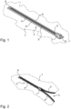
- THE figures 1 and 2 partially represent an article 1, in particular leather goods and for example a bag, provided with an opening and closing device 2, of the zipper type, respectively in a closed configuration and in an opening configuration.
- Article 1 includes an access opening 3 around which the zipper 2 is mechanically secured.
- the zipper 2 comprises a slide 4 having two connecting strips 5 which are each mechanically secured to an internal edge 6 delimiting the access opening of the article 1.
- the zipper 2 further comprises a slider 7 movable along the slide 4 between two stops 8 and 9, one of which is called low and the other is called high (see below in more detail ).
- the zipper 2 is said to have vertical opening because it allows the joining and separation of the two connecting strips 5 thanks to the action of the slider 7, in a direction perpendicular to the plane created by them.
- the connecting strips 5 move apart in a vertical direction (or perpendicular to the plane formed by them when the slide 4 is closed).
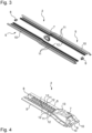
- FIG. 3 shows zipper 2 taken in isolation and in exploded view.
- Each connecting strip 5 of the slide 4 comprises a fixing rod 10 which extends longitudinally between the stops 8 and 9 and which is intended to be secured to the article.
- the fixing ring 10 can be sewn with the article.
- Each connecting strip 5 here further comprises a plurality of spacers 11 each configured to be mounted on the respective fixing rod 10.
- Each connecting strip 5 comprises a plurality of teeth 12 each configured to also be mounted on the respective fixing rod 10, with here between two successive teeth 12 a spacer 11 which is interposed.
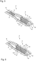
- THE figures 4 to 6 show in more detail a part of the zipper 2 which is assembled, in a closed configuration, then in an opening configuration and finally in an open configuration.
- the cursor 7 has been moved from a position where it abuts against the so-called upper stop 9 ( Figure 4 ), passing through an intermediate position ( Figure 5 ), towards a position where it is opposite and abutting against the so-called lower stop 8 ( Figure 6 ), and this according to a predetermined direction of movement called closing.
- the slider 7 is provided with a trigger guard 13 to which a pull tab (not shown) can be attached to facilitate the movement of the slider 7.
- the slider 7 is at a distance from the stop stops 8 and 9 and the teeth 12 of the connecting strips 5 which are located between the slider 7 and the stop stop 8 are coupled to form links, so that the slide 4 is closed on this zone, while the teeth 12 of the connecting strip 5 which are located between the slider 7 and the stop 9 are uncoupled, or separated, so that the slide 4 is open on this other zone .
- the teeth 12 of one of the connecting strips 5 are offset relative to the teeth 12 of the other of the connecting strips 5 along an axis perpendicular to the plane that the connecting strips 5 form when the teeth 12 are coupled and slide 4 closed.
- the slider 7 comprises a body provided with a first opening 15 located at a first end 14 of the slider 7, with two second openings 17 superimposed and located at a second end 16 opposite the first end 14.
- the body of the slider 7 is thus larger on the side of its second end 16 than on the side of its first end 14, and therefore smaller on the side of its first end 14 than on the side of its second end 16. This is why that the stopper 9 which is located on the side of the second end 16 of the slider 7 is here called high, while the stopper 8 which is located on the side of the first end 14 of the slider 7 is here called low .
- the slider 7 is further provided with an upper ramp 18 formed in the body and extending from the first opening 15 to one of the second openings 17, and with a lower ramp 19 formed in the body and s extending from the first opening 15 to the other of the second openings 17.
- the ramps 18 and 19 are stepped, while on the side of the cursor 7 where the first opening 15 is located, the ramps 18 and 19 come together and form a common ramp .
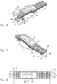
- the slider 7 is also provided with lateral openings 20 provided on either side of the body, along the upper 18 and lower 19 ramps (visible in particular on the figures 10 and 11 ).
- the first opening 15 and the two second openings 17 provided in the body of the slider 7 present here respectively a contour provided with a radius 21, 22 (visible in particular on the figures 10, 11 , 13 and 14 ).
- Each tooth 12 of the connecting strips 5 here has a first face 23 and a second face 24 opposite the first face 23.
- Each tooth 12 of the connecting strips 5 has a first fixing member formed here by a protuberance 25, here of hemispherical shape and provided projecting from its first face 23, and a second fixing member formed here by a housing 26, here of hemispherical shape and formed in a recess on its second face 24.
- Each tooth 12 of one of the connecting strips 5 is configured to cooperate with one or two teeth of the other of the connecting strips 5, via the reception of the protuberances 25 in the housings 26, so as to form links.
- the zipper 2 is thus configured so that, under an action of movement of the slider 7 in the opening direction, the teeth 12 which cooperate enter the slider 7 through its first opening 15, separate and travel respectively along of its upper and lower ramps 18 and 19 until it exits the slider 7 respectively and individually through its second two superimposed openings 17.
- the zipper 2 is configured so that the teeth 12 enter individually and separately through the two respective second openings 17 and superimposed on the cursor 7, travel respectively along the upper and lower ramps 18 and 19 until entering into cooperation at the level of the first opening 15 of the cursor 7.
- the protuberances 25 come out of the housings 26 so that the teeth 12 which form the links separate passing from the common ramp towards the upper ramps and lower 18 and 19, each being dedicated respectively to the teeth 12 of a strip of respective connection 5.
- the teeth 12 meet passing from the upper and lower ramps 18 and 19 towards the common ramp where the protuberances 25 enter into the housings 26 so that the teeth 12 mate and form the links.
- teeth 12A, 12B and 12C are shown the coupling phases of three teeth denoted 12A, 12B and 12C to form a link when the cursor 7 is moved in the closing direction; and the uncoupling of three other teeth denoted 12D, 12E and 12F when the cursor 7 is moved in the opening direction.
- teeth 12A and 12E are confused and teeth 12B and 12F are confused.
- each tooth 12 of the connecting strips 5 has a contour 27 at least partially cylindrical, with each of the first and second faces 23, 24 which joins the contour 27.
- each tooth 12 also has an extension 28 provided on one side of the contour 27 and which is configured to pass through a respective lateral opening 20 of the slider 7.
- the extensions 28 are here substantially C-shaped and are configured to receive one of the respective fixing rods.
- the extensions 28 generally have a shape similar to that of the spacers 11.
- each tooth 12 is further provided, on its first face 23, with two first rounded portions 30 provided on either side of the protuberance 25 and, on its second face 24, with two second rounded portions 31 provided with either side of housing 26.
- the first two rounded portions 30 extend from the first face 23 to the contour 27, and the two second rounded portions 31 extend from the second face 24 to the contour 27.
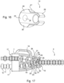
- the first rounded portions 30 and the second rounded portions 31 make it possible to facilitate the coupling and uncoupling of the protuberances 23 with the housings 25 to assemble and separate the teeth 12 and thus form or split the links, of which the teeth 12 are move apart or move closer together in a vertical direction.
- the guiding of the teeth 12 in the upper and lower ramps 18 and 19 of the slider 7 is therefore facilitated. This is clearly visible on the Figure 17 .
- protuberances 25 and the housings 26 make it possible to create ball joints which, in combination with the first and second rounded portions 30 and 31, further facilitate the guiding of the teeth 12 in the slider 7 as well as the opening and closing the slide 4 in the direction perpendicular to the plane created by the connecting strips 5.
- first rounded portions 30 and the second rounded portions 31, in combination with the radii 21 and 22 respectively of the first opening 15 and the two second openings 17, also facilitate the entry and exit of the teeth 12 in cursor 7.
- first rounded portions 30 and the second rounded portions 31 on the teeth is provided so that a first rounded portion 30 and a second rounded portion 31 are generally turned towards the upper ramp 18 of the cursor 7 depending on the direction of movement of the latter, while another first rounded portion 30 and another second rounded portion 31 are generally turned towards the lower ramp 19 of the cursor 7 depending on the direction of movement of the latter .
- first rounded portions 30 and the second rounded portions 31 extend on the side of the extensions 28 of the teeth 12.
- the first tooth fixing member and/or the second tooth fixing member may be formed by hooks or have prismatic shapes rather than hemispherical ones, or any other suitable shape.
- the zipper may have several movable sliders between the stoppers. If necessary, it may be two lower stops rather than one lower stop and one upper stop.
- the connecting strips may not be attached and rather come as part of the item.
- the spacers may be formed integrally with the teeth or the closure may not have a spacer.
- the item may be made of textile rather than leather; and/or the item may be a wallet rather than a bag, or any other item in the field of leather goods.
Landscapes
- Slide Fasteners (AREA)
Claims (10)
- Öffnungs- und Schließvorrichtung vom Reißverschlusstyp (2), die Folgendes enthält:- eine Führungsbahn (4), die zwei Verbindungsbänder (5) aufweisen, die jeweils mit einer Vielzahl von Zähnen (12) versehen sind, wobei jeder Zahn ein erstes Fixierelement (25), das auf einer ersten Seite (23) ausgebildet ist, und ein zweites Fixierelement (26) aufweist, das auf einer zweiten Seite (24) des Zahns ausgebildet ist, die der ersten Seite gegenüberliegt, und jeder Zahn eines der beiden Verbindungsbänder dazu konfiguriert ist, mit mindestens einem Zahn des anderen Verbindungsbands mittels des ersten und des zweiten Fixierungselements zusammenzuwirken, um Schließglieder zu bilden; und- einen Schiebekörper (7), der mit einer ersten Öffnung (15), die sich an einem ersten Ende (14) befindet, zwei übereinander angeordneten zweiten Öffnungen (17), die sich an einem zweiten Ende (16) gegenüber dem ersten Ende befinden, und einer oberen Steigung (18), die sich von der ersten Öffnung bis zu einer der beiden zweiten Öffnungen erstreckt, und einer unteren Steigung (19) versehen ist, die sich von der ersten Öffnung bis zur anderen der zweiten Öffnungen erstreckt;wobei die Öffnungs- und Schließvorrichtung derart konfiguriert ist, dass unter der Wirkung des Schiebekörpers in einer vorbestimmten Öffnungsrichtung die zusammenwirkenden Zähne in den Schiebekörper durch seine erste Öffnung eindringen, sich entlang der oberen und der unteren Steigung trennen und entlang diesen laufen, bis sie jeweils und einzeln durch ihre beiden übereinanderliegenden zweiten Öffnungen aus dem Schiebekörper heraustreten;wobei die Öffnungs- und Schließvorrichtung derart konfiguriert ist, dass unter der Wirkung der Bewegung des Schiebekörpers in einer zur vorbestimmten Öffnungsrichtung entgegengesetzten Schließrichtung die Zähne der beiden Verbindungsbänder einzeln und getrennt durch die beiden jeweiligen, übereinanderliegenden beiden zweiten Öffnungen des Schiebekörpers eintreten, jeweils entlang der oberen und der unteren Steigung laufen, bis sie an der ersten Öffnung des Schiebekörpers zusammenwirken,und wobei die Öffnungs- und Schließvorrichtung dadurch gekennzeichnet ist, dass jeder Zahn (12) mit mindestens einem ersten abgerundeten Abschnitt (30) auf seiner ersten Seite (23), der sich von dem ersten Fixierungselement (25) unterscheidet, und/oder mindestens einem zweiten abgerundeten Abschnitt (31) auf seiner zweiten Seite (24) versehen ist, der sich von dem zweiten Fixierungselement (26) unterscheidet, dadurch gekennzeichnet, dass das erste Fixierungselement durch einen halbkugelförmigen Vorsprung (25) gebildet wird, der auf der ersten Seite (23) des Zahns (12) vorspringend ausgebildet ist, und das zweite Fixierungselement durch eine halbkugelförmige Aufnahme (26) gebildet wird, die auf der zweiten Seite (24) des Zahns vertieft ausgebildet ist.
- Öffnungs- und Schließvorrichtung nach Anspruch 1, dadurch gekennzeichnet, dass jeder Zahn (12) ein zumindest teilweise zylindrisches Profil (27) aufweist, wobei jede der ersten und der zweiten Seite (23, 24) an das Profil anschließt und der mindestens eine erste abgerundete Abschnitt (30) sich von der ersten Seite bis zum Profil erstreckt und/oder der mindestens eine zweite abgerundete Abschnitt (31) sich von der zweiten Seite bis zum Profil erstreckt.
- Öffnungs- und Schließvorrichtung nach einem der Ansprüche 1 bis 2, dadurch gekennzeichnet, dass jeder Zahn (12) zwei erste abgerundete Abschnitte (30) aufweist, die auf beiden Seiten des ersten Fixierungselements (25) ausgebildet sind, und/oder zwei zweite abgerundete Abschnitte (31), die auf beiden Seiten des zweiten Fixierungselements (26) ausgebildet sind.
- Öffnungs- und Schließvorrichtung nach einem der Ansprüche 1 bis 3, dadurch gekennzeichnet, dass jeder Zahn (12) eine auf einer Seite des Profils (27) ausgebildete Verlängerung (28) aufweist und der Schiebekörper (7) entlang der oberen und der unteren Rampe (18, 19) mit seitlichen Öffnungen (20) für den Durchgang der Verlängerungen der Zähne versehen ist.
- Öffnungs- und Schließvorrichtung nach Anspruch 4, dadurch gekennzeichnet, dass jedes Verbindungsband (5) einen Befestigungssteg (10) aufweist und die Verlängerung (28) des Zahns (12) ein Loch aufweist, in das der jeweilige Befestigungssteg eingeführt ist, um die Zähne am Verbindungsband (5) zu befestigen.
- Öffnungs- und Schließvorrichtung nach einem der Ansprüche 1 bis 5, dadurch gekennzeichnet, dass jedes Verbindungsband (5) eine Vielzahl von Abstandshaltern (11) enthält, die jeweils zwischen zwei aufeinanderfolgenden Zähnen (12) eingesetzt sind.
- Öffnungs- und Schließvorrichtung nach einem der Ansprüche 1 bis 6, dadurch gekennzeichnet, dass die erste Öffnung (15) und/oder die beiden zweiten Öffnungen (17) des Schiebekörpers (7) ein Profil mit einem Umkreis (21, 22) aufweisen.
- Öffnungs- und Schließvorrichtung nach einem der Ansprüche 1 bis 7, dadurch gekennzeichnet, dass sie zwei Endanschläge (8, 9), die sich auf beiden Seiten der Führungsbahn (4) befinden, und einen oder mehrere Schiebekörper (7) enthält, die zwischen den beiden Endanschlägen beweglich sind.
- Artikel, insbesondere Lederartikel, der eine Zugangsöffnung (3) und eine Öffnungs- und Schließvorrichtung vom Reißverschlusstyp (2) nach einem der Ansprüche 1 bis 8 enthält, die mechanisch rund um die im Artikel (1) ausgebildete Zugangsöffnung befestigt ist.
- Artikel nach Anspruch 9, dadurch gekennzeichnet, dass seine Zugangsöffnung (3) durch eine Innenkante (6) begrenzt ist, an der die Verbindungsbänder (5) der Öffnungs- und Schließvorrichtung mechanisch befestigt ist.
Priority Applications (1)
| Application Number | Priority Date | Filing Date | Title |
|---|---|---|---|
| EP23212103.8A EP4302637B1 (de) | 2021-05-18 | 2022-05-18 | Öffnungs- und schliessvorrichtung vom typ reissverschluss für einen artikel, insbesondere für lederwaren |
Applications Claiming Priority (1)
| Application Number | Priority Date | Filing Date | Title |
|---|---|---|---|
| FR2105197A FR3122975A1 (fr) | 2021-05-18 | 2021-05-18 | Dispositif d’ouverture et de fermeture, du type fermeture à glissière, pour article notamment de maroquinerie |
Related Child Applications (2)
| Application Number | Title | Priority Date | Filing Date |
|---|---|---|---|
| EP23212103.8A Division EP4302637B1 (de) | 2021-05-18 | 2022-05-18 | Öffnungs- und schliessvorrichtung vom typ reissverschluss für einen artikel, insbesondere für lederwaren |
| EP23212103.8A Division-Into EP4302637B1 (de) | 2021-05-18 | 2022-05-18 | Öffnungs- und schliessvorrichtung vom typ reissverschluss für einen artikel, insbesondere für lederwaren |
Publications (2)
| Publication Number | Publication Date |
|---|---|
| EP4091494A1 EP4091494A1 (de) | 2022-11-23 |
| EP4091494B1 true EP4091494B1 (de) | 2024-02-21 |
Family
ID=77021474
Family Applications (2)
| Application Number | Title | Priority Date | Filing Date |
|---|---|---|---|
| EP23212103.8A Active EP4302637B1 (de) | 2021-05-18 | 2022-05-18 | Öffnungs- und schliessvorrichtung vom typ reissverschluss für einen artikel, insbesondere für lederwaren |
| EP22305736.5A Active EP4091494B1 (de) | 2021-05-18 | 2022-05-18 | Öffnungs- und schliessvorrichtung vom typ reissverschluss für einen artikel, insbesondere für lederwaren |
Family Applications Before (1)
| Application Number | Title | Priority Date | Filing Date |
|---|---|---|---|
| EP23212103.8A Active EP4302637B1 (de) | 2021-05-18 | 2022-05-18 | Öffnungs- und schliessvorrichtung vom typ reissverschluss für einen artikel, insbesondere für lederwaren |
Country Status (3)
| Country | Link |
|---|---|
| EP (2) | EP4302637B1 (de) |
| CN (1) | CN115363323A (de) |
| FR (1) | FR3122975A1 (de) |
Family Cites Families (4)
| Publication number | Priority date | Publication date | Assignee | Title |
|---|---|---|---|---|
| DE10146151B4 (de) * | 2001-07-13 | 2008-05-08 | Shih-Chang Wang | Reißverschluss |
| EP2700327B1 (de) | 2011-04-18 | 2018-08-08 | YKK Corporation | Verfahren zur herstellung eines metallschieberes für reissverschlüsse |
| JP2015116355A (ja) * | 2013-12-19 | 2015-06-25 | Ykk株式会社 | スライドファスナー |
| CN106388142B (zh) * | 2016-12-02 | 2023-06-27 | 浙江伟星实业发展股份有限公司 | 一种拉链及日用品 |
-
2021
- 2021-05-18 FR FR2105197A patent/FR3122975A1/fr active Pending
-
2022
- 2022-05-17 CN CN202210533903.0A patent/CN115363323A/zh active Pending
- 2022-05-18 EP EP23212103.8A patent/EP4302637B1/de active Active
- 2022-05-18 EP EP22305736.5A patent/EP4091494B1/de active Active
Also Published As
| Publication number | Publication date |
|---|---|
| FR3122975A1 (fr) | 2022-11-25 |
| EP4302637A3 (de) | 2024-02-28 |
| CN115363323A (zh) | 2022-11-22 |
| EP4302637A2 (de) | 2024-01-10 |
| EP4302637B1 (de) | 2026-04-08 |
| EP4091494A1 (de) | 2022-11-23 |
Similar Documents
| Publication | Publication Date | Title |
|---|---|---|
| EP0116511B1 (de) | Schutzhelm, insbesondere für Benutzer von Kraftfahrzeugen | |
| FR2924098A1 (fr) | Capuchon pour pulverisateur | |
| CH705149A1 (fr) | Fermoir extensible pour bracelet notamment d'une montre. | |
| EP1841339B1 (de) | Entfaltbare schnalle für armband | |
| FR2544970A1 (fr) | Boite a poudre de maquillage et son pinceau applicateur | |
| EP0569302B1 (de) | Befestigungsschnalle für den Kinnriemen eines Schutzhelms | |
| EP4091494B1 (de) | Öffnungs- und schliessvorrichtung vom typ reissverschluss für einen artikel, insbesondere für lederwaren | |
| EP4176757B1 (de) | Verschluss mit klappöse | |
| EP0115364B1 (de) | Faltverschluss für Armbänder | |
| EP0869242A1 (de) | Verriegelungsbeschlag für Schiebeflügel | |
| EP3781443B1 (de) | Zur positionierung auf einem fahrzeugdach bestimmte dachbügelanordnung | |
| EP0333543B1 (de) | Vorrichtung zur beweglichen Verbindung eines Objektes, insbesondere eines Schmuckstückes, auf einer Unterlage | |
| FR2610179A1 (fr) | Curseur verrouillable | |
| EP3599930B1 (de) | Faltschnallenverschluss | |
| FR2642381A1 (fr) | Dispositif de cloisonnement pour la partie arriere de l'habitacle d'un vehicule | |
| EP1157937B1 (de) | Abnehmbarer Verschluss für Flüssigkeitsbehälter | |
| CH720378A2 (fr) | Fermoir de bracelet. | |
| EP4090195B1 (de) | Gepäckstückledergegenstand | |
| EP4388918A1 (de) | Armbandverschluss | |
| EP4445792B1 (de) | Zweiteiliger ohrring mit optimiserten leitungsmittel von einem teil in den anderen | |
| EP4523563A1 (de) | Kettenglied für einen artikel, kettel mit einem solchen glied und artikel mit einem solchen kettenglied | |
| EP4265452A1 (de) | Mechanismus zur bildung eines gelenks einer abdeckstruktur für ein fahrzeug und solch eine vorrichtung | |
| CH678793A5 (en) | Ski boot in synthetic material with replaceable leg - has base of leg having horizontal axle fitting into cylindrical hollow in projection on back of shell | |
| CH719306B1 (fr) | Fermoir pour bracelet. | |
| CH664677A5 (fr) | Fermoir pour bracelet metallique. |
Legal Events
| Date | Code | Title | Description |
|---|---|---|---|
| PUAI | Public reference made under article 153(3) epc to a published international application that has entered the european phase |
Free format text: ORIGINAL CODE: 0009012 |
|
| STAA | Information on the status of an ep patent application or granted ep patent |
Free format text: STATUS: THE APPLICATION HAS BEEN PUBLISHED |
|
| AK | Designated contracting states |
Kind code of ref document: A1 Designated state(s): AL AT BE BG CH CY CZ DE DK EE ES FI FR GB GR HR HU IE IS IT LI LT LU LV MC MK MT NL NO PL PT RO RS SE SI SK SM TR |
|
| STAA | Information on the status of an ep patent application or granted ep patent |
Free format text: STATUS: REQUEST FOR EXAMINATION WAS MADE |
|
| 17P | Request for examination filed |
Effective date: 20230213 |
|
| RBV | Designated contracting states (corrected) |
Designated state(s): AL AT BE BG CH CY CZ DE DK EE ES FI FR GB GR HR HU IE IS IT LI LT LU LV MC MK MT NL NO PL PT RO RS SE SI SK SM TR |
|
| RIC1 | Information provided on ipc code assigned before grant |
Ipc: A44B 19/26 20060101ALN20230703BHEP Ipc: A45C 13/10 20060101ALI20230703BHEP Ipc: A44B 19/04 20060101AFI20230703BHEP |
|
| GRAP | Despatch of communication of intention to grant a patent |
Free format text: ORIGINAL CODE: EPIDOSNIGR1 |
|
| STAA | Information on the status of an ep patent application or granted ep patent |
Free format text: STATUS: GRANT OF PATENT IS INTENDED |
|
| INTG | Intention to grant announced |
Effective date: 20230913 |
|
| GRAS | Grant fee paid |
Free format text: ORIGINAL CODE: EPIDOSNIGR3 |
|
| GRAA | (expected) grant |
Free format text: ORIGINAL CODE: 0009210 |
|
| STAA | Information on the status of an ep patent application or granted ep patent |
Free format text: STATUS: THE PATENT HAS BEEN GRANTED |
|
| AK | Designated contracting states |
Kind code of ref document: B1 Designated state(s): AL AT BE BG CH CY CZ DE DK EE ES FI FR GB GR HR HU IE IS IT LI LT LU LV MC MK MT NL NO PL PT RO RS SE SI SK SM TR |
|
| REG | Reference to a national code |
Ref country code: GB Ref legal event code: FG4D Free format text: NOT ENGLISH |
|
| REG | Reference to a national code |
Ref country code: CH Ref legal event code: EP |
|
| REG | Reference to a national code |
Ref country code: IE Ref legal event code: FG4D Free format text: LANGUAGE OF EP DOCUMENT: FRENCH |
|
| REG | Reference to a national code |
Ref country code: DE Ref legal event code: R096 Ref document number: 602022002063 Country of ref document: DE |
|
| REG | Reference to a national code |
Ref country code: LT Ref legal event code: MG9D |
|
| REG | Reference to a national code |
Ref country code: NL Ref legal event code: MP Effective date: 20240221 |
|
| PG25 | Lapsed in a contracting state [announced via postgrant information from national office to epo] |
Ref country code: IS Free format text: LAPSE BECAUSE OF FAILURE TO SUBMIT A TRANSLATION OF THE DESCRIPTION OR TO PAY THE FEE WITHIN THE PRESCRIBED TIME-LIMIT Effective date: 20240621 |
|
| PG25 | Lapsed in a contracting state [announced via postgrant information from national office to epo] |
Ref country code: LT Free format text: LAPSE BECAUSE OF FAILURE TO SUBMIT A TRANSLATION OF THE DESCRIPTION OR TO PAY THE FEE WITHIN THE PRESCRIBED TIME-LIMIT Effective date: 20240221 |
|
| PG25 | Lapsed in a contracting state [announced via postgrant information from national office to epo] |
Ref country code: GR Free format text: LAPSE BECAUSE OF FAILURE TO SUBMIT A TRANSLATION OF THE DESCRIPTION OR TO PAY THE FEE WITHIN THE PRESCRIBED TIME-LIMIT Effective date: 20240522 |
|
| REG | Reference to a national code |
Ref country code: AT Ref legal event code: MK05 Ref document number: 1658291 Country of ref document: AT Kind code of ref document: T Effective date: 20240221 |
|
| PG25 | Lapsed in a contracting state [announced via postgrant information from national office to epo] |
Ref country code: RS Free format text: LAPSE BECAUSE OF FAILURE TO SUBMIT A TRANSLATION OF THE DESCRIPTION OR TO PAY THE FEE WITHIN THE PRESCRIBED TIME-LIMIT Effective date: 20240521 Ref country code: NL Free format text: LAPSE BECAUSE OF FAILURE TO SUBMIT A TRANSLATION OF THE DESCRIPTION OR TO PAY THE FEE WITHIN THE PRESCRIBED TIME-LIMIT Effective date: 20240221 Ref country code: HR Free format text: LAPSE BECAUSE OF FAILURE TO SUBMIT A TRANSLATION OF THE DESCRIPTION OR TO PAY THE FEE WITHIN THE PRESCRIBED TIME-LIMIT Effective date: 20240221 |
|
| PG25 | Lapsed in a contracting state [announced via postgrant information from national office to epo] |
Ref country code: ES Free format text: LAPSE BECAUSE OF FAILURE TO SUBMIT A TRANSLATION OF THE DESCRIPTION OR TO PAY THE FEE WITHIN THE PRESCRIBED TIME-LIMIT Effective date: 20240221 |
|
| PG25 | Lapsed in a contracting state [announced via postgrant information from national office to epo] |
Ref country code: AT Free format text: LAPSE BECAUSE OF FAILURE TO SUBMIT A TRANSLATION OF THE DESCRIPTION OR TO PAY THE FEE WITHIN THE PRESCRIBED TIME-LIMIT Effective date: 20240221 |
|
| PG25 | Lapsed in a contracting state [announced via postgrant information from national office to epo] |
Ref country code: RS Free format text: LAPSE BECAUSE OF FAILURE TO SUBMIT A TRANSLATION OF THE DESCRIPTION OR TO PAY THE FEE WITHIN THE PRESCRIBED TIME-LIMIT Effective date: 20240521 Ref country code: NO Free format text: LAPSE BECAUSE OF FAILURE TO SUBMIT A TRANSLATION OF THE DESCRIPTION OR TO PAY THE FEE WITHIN THE PRESCRIBED TIME-LIMIT Effective date: 20240521 Ref country code: NL Free format text: LAPSE BECAUSE OF FAILURE TO SUBMIT A TRANSLATION OF THE DESCRIPTION OR TO PAY THE FEE WITHIN THE PRESCRIBED TIME-LIMIT Effective date: 20240221 Ref country code: LT Free format text: LAPSE BECAUSE OF FAILURE TO SUBMIT A TRANSLATION OF THE DESCRIPTION OR TO PAY THE FEE WITHIN THE PRESCRIBED TIME-LIMIT Effective date: 20240221 Ref country code: IS Free format text: LAPSE BECAUSE OF FAILURE TO SUBMIT A TRANSLATION OF THE DESCRIPTION OR TO PAY THE FEE WITHIN THE PRESCRIBED TIME-LIMIT Effective date: 20240621 Ref country code: HR Free format text: LAPSE BECAUSE OF FAILURE TO SUBMIT A TRANSLATION OF THE DESCRIPTION OR TO PAY THE FEE WITHIN THE PRESCRIBED TIME-LIMIT Effective date: 20240221 Ref country code: GR Free format text: LAPSE BECAUSE OF FAILURE TO SUBMIT A TRANSLATION OF THE DESCRIPTION OR TO PAY THE FEE WITHIN THE PRESCRIBED TIME-LIMIT Effective date: 20240522 Ref country code: FI Free format text: LAPSE BECAUSE OF FAILURE TO SUBMIT A TRANSLATION OF THE DESCRIPTION OR TO PAY THE FEE WITHIN THE PRESCRIBED TIME-LIMIT Effective date: 20240221 Ref country code: ES Free format text: LAPSE BECAUSE OF FAILURE TO SUBMIT A TRANSLATION OF THE DESCRIPTION OR TO PAY THE FEE WITHIN THE PRESCRIBED TIME-LIMIT Effective date: 20240221 Ref country code: BG Free format text: LAPSE BECAUSE OF FAILURE TO SUBMIT A TRANSLATION OF THE DESCRIPTION OR TO PAY THE FEE WITHIN THE PRESCRIBED TIME-LIMIT Effective date: 20240221 Ref country code: AT Free format text: LAPSE BECAUSE OF FAILURE TO SUBMIT A TRANSLATION OF THE DESCRIPTION OR TO PAY THE FEE WITHIN THE PRESCRIBED TIME-LIMIT Effective date: 20240221 |
|
| PG25 | Lapsed in a contracting state [announced via postgrant information from national office to epo] |
Ref country code: PL Free format text: LAPSE BECAUSE OF FAILURE TO SUBMIT A TRANSLATION OF THE DESCRIPTION OR TO PAY THE FEE WITHIN THE PRESCRIBED TIME-LIMIT Effective date: 20240221 Ref country code: PT Free format text: LAPSE BECAUSE OF FAILURE TO SUBMIT A TRANSLATION OF THE DESCRIPTION OR TO PAY THE FEE WITHIN THE PRESCRIBED TIME-LIMIT Effective date: 20240621 |
|
| PG25 | Lapsed in a contracting state [announced via postgrant information from national office to epo] |
Ref country code: SE Free format text: LAPSE BECAUSE OF FAILURE TO SUBMIT A TRANSLATION OF THE DESCRIPTION OR TO PAY THE FEE WITHIN THE PRESCRIBED TIME-LIMIT Effective date: 20240221 Ref country code: PT Free format text: LAPSE BECAUSE OF FAILURE TO SUBMIT A TRANSLATION OF THE DESCRIPTION OR TO PAY THE FEE WITHIN THE PRESCRIBED TIME-LIMIT Effective date: 20240621 Ref country code: PL Free format text: LAPSE BECAUSE OF FAILURE TO SUBMIT A TRANSLATION OF THE DESCRIPTION OR TO PAY THE FEE WITHIN THE PRESCRIBED TIME-LIMIT Effective date: 20240221 Ref country code: LV Free format text: LAPSE BECAUSE OF FAILURE TO SUBMIT A TRANSLATION OF THE DESCRIPTION OR TO PAY THE FEE WITHIN THE PRESCRIBED TIME-LIMIT Effective date: 20240221 |
|
| PG25 | Lapsed in a contracting state [announced via postgrant information from national office to epo] |
Ref country code: DK Free format text: LAPSE BECAUSE OF FAILURE TO SUBMIT A TRANSLATION OF THE DESCRIPTION OR TO PAY THE FEE WITHIN THE PRESCRIBED TIME-LIMIT Effective date: 20240221 |
|
| PG25 | Lapsed in a contracting state [announced via postgrant information from national office to epo] |
Ref country code: SM Free format text: LAPSE BECAUSE OF FAILURE TO SUBMIT A TRANSLATION OF THE DESCRIPTION OR TO PAY THE FEE WITHIN THE PRESCRIBED TIME-LIMIT Effective date: 20240221 |
|
| PG25 | Lapsed in a contracting state [announced via postgrant information from national office to epo] |
Ref country code: CZ Free format text: LAPSE BECAUSE OF FAILURE TO SUBMIT A TRANSLATION OF THE DESCRIPTION OR TO PAY THE FEE WITHIN THE PRESCRIBED TIME-LIMIT Effective date: 20240221 Ref country code: EE Free format text: LAPSE BECAUSE OF FAILURE TO SUBMIT A TRANSLATION OF THE DESCRIPTION OR TO PAY THE FEE WITHIN THE PRESCRIBED TIME-LIMIT Effective date: 20240221 |
|
| PG25 | Lapsed in a contracting state [announced via postgrant information from national office to epo] |
Ref country code: SK Free format text: LAPSE BECAUSE OF FAILURE TO SUBMIT A TRANSLATION OF THE DESCRIPTION OR TO PAY THE FEE WITHIN THE PRESCRIBED TIME-LIMIT Effective date: 20240221 |
|
| PG25 | Lapsed in a contracting state [announced via postgrant information from national office to epo] |
Ref country code: SM Free format text: LAPSE BECAUSE OF FAILURE TO SUBMIT A TRANSLATION OF THE DESCRIPTION OR TO PAY THE FEE WITHIN THE PRESCRIBED TIME-LIMIT Effective date: 20240221 Ref country code: SK Free format text: LAPSE BECAUSE OF FAILURE TO SUBMIT A TRANSLATION OF THE DESCRIPTION OR TO PAY THE FEE WITHIN THE PRESCRIBED TIME-LIMIT Effective date: 20240221 Ref country code: RO Free format text: LAPSE BECAUSE OF FAILURE TO SUBMIT A TRANSLATION OF THE DESCRIPTION OR TO PAY THE FEE WITHIN THE PRESCRIBED TIME-LIMIT Effective date: 20240221 Ref country code: EE Free format text: LAPSE BECAUSE OF FAILURE TO SUBMIT A TRANSLATION OF THE DESCRIPTION OR TO PAY THE FEE WITHIN THE PRESCRIBED TIME-LIMIT Effective date: 20240221 Ref country code: DK Free format text: LAPSE BECAUSE OF FAILURE TO SUBMIT A TRANSLATION OF THE DESCRIPTION OR TO PAY THE FEE WITHIN THE PRESCRIBED TIME-LIMIT Effective date: 20240221 Ref country code: CZ Free format text: LAPSE BECAUSE OF FAILURE TO SUBMIT A TRANSLATION OF THE DESCRIPTION OR TO PAY THE FEE WITHIN THE PRESCRIBED TIME-LIMIT Effective date: 20240221 |
|
| REG | Reference to a national code |
Ref country code: DE Ref legal event code: R097 Ref document number: 602022002063 Country of ref document: DE |
|
| PLBE | No opposition filed within time limit |
Free format text: ORIGINAL CODE: 0009261 |
|
| STAA | Information on the status of an ep patent application or granted ep patent |
Free format text: STATUS: NO OPPOSITION FILED WITHIN TIME LIMIT |
|
| PG25 | Lapsed in a contracting state [announced via postgrant information from national office to epo] |
Ref country code: MC Free format text: LAPSE BECAUSE OF FAILURE TO SUBMIT A TRANSLATION OF THE DESCRIPTION OR TO PAY THE FEE WITHIN THE PRESCRIBED TIME-LIMIT Effective date: 20240221 |
|
| PG25 | Lapsed in a contracting state [announced via postgrant information from national office to epo] |
Ref country code: LU Free format text: LAPSE BECAUSE OF NON-PAYMENT OF DUE FEES Effective date: 20240518 |
|
| 26N | No opposition filed |
Effective date: 20241122 |
|
| PG25 | Lapsed in a contracting state [announced via postgrant information from national office to epo] |
Ref country code: MC Free format text: LAPSE BECAUSE OF FAILURE TO SUBMIT A TRANSLATION OF THE DESCRIPTION OR TO PAY THE FEE WITHIN THE PRESCRIBED TIME-LIMIT Effective date: 20240221 Ref country code: LU Free format text: LAPSE BECAUSE OF NON-PAYMENT OF DUE FEES Effective date: 20240518 |
|
| REG | Reference to a national code |
Ref country code: BE Ref legal event code: MM Effective date: 20240531 |
|
| PG25 | Lapsed in a contracting state [announced via postgrant information from national office to epo] |
Ref country code: IE Free format text: LAPSE BECAUSE OF NON-PAYMENT OF DUE FEES Effective date: 20240518 |
|
| PG25 | Lapsed in a contracting state [announced via postgrant information from national office to epo] |
Ref country code: SI Free format text: LAPSE BECAUSE OF FAILURE TO SUBMIT A TRANSLATION OF THE DESCRIPTION OR TO PAY THE FEE WITHIN THE PRESCRIBED TIME-LIMIT Effective date: 20240221 Ref country code: BE Free format text: LAPSE BECAUSE OF NON-PAYMENT OF DUE FEES Effective date: 20240531 |
|
| P01 | Opt-out of the competence of the unified patent court (upc) registered |
Free format text: CASE NUMBER: APP_17458/2025 Effective date: 20250410 |
|
| PGFP | Annual fee paid to national office [announced via postgrant information from national office to epo] |
Ref country code: DE Payment date: 20250529 Year of fee payment: 4 |
|
| PGFP | Annual fee paid to national office [announced via postgrant information from national office to epo] |
Ref country code: IT Payment date: 20250531 Year of fee payment: 4 |
|
| PGFP | Annual fee paid to national office [announced via postgrant information from national office to epo] |
Ref country code: FR Payment date: 20250414 Year of fee payment: 4 |
|
| PG25 | Lapsed in a contracting state [announced via postgrant information from national office to epo] |
Ref country code: CY Free format text: LAPSE BECAUSE OF FAILURE TO SUBMIT A TRANSLATION OF THE DESCRIPTION OR TO PAY THE FEE WITHIN THE PRESCRIBED TIME-LIMIT; INVALID AB INITIO Effective date: 20220518 |
|
| PG25 | Lapsed in a contracting state [announced via postgrant information from national office to epo] |
Ref country code: HU Free format text: LAPSE BECAUSE OF FAILURE TO SUBMIT A TRANSLATION OF THE DESCRIPTION OR TO PAY THE FEE WITHIN THE PRESCRIBED TIME-LIMIT; INVALID AB INITIO Effective date: 20220518 |
|
| REG | Reference to a national code |
Ref country code: CH Ref legal event code: H13 Free format text: ST27 STATUS EVENT CODE: U-0-0-H10-H13 (AS PROVIDED BY THE NATIONAL OFFICE) Effective date: 20251223 |
|
| PG25 | Lapsed in a contracting state [announced via postgrant information from national office to epo] |
Ref country code: CH Free format text: LAPSE BECAUSE OF NON-PAYMENT OF DUE FEES Effective date: 20250531 |