US4901373A - Helmet retention system with adjustable buckle - Google Patents
Helmet retention system with adjustable buckle Download PDFInfo
- Publication number
- US4901373A US4901373A US07/164,852 US16485288A US4901373A US 4901373 A US4901373 A US 4901373A US 16485288 A US16485288 A US 16485288A US 4901373 A US4901373 A US 4901373A
- Authority
- US
- United States
- Prior art keywords
- shell
- strap
- chin strap
- looping
- openings
- Prior art date
- Legal status (The legal status is an assumption and is not a legal conclusion. Google has not performed a legal analysis and makes no representation as to the accuracy of the status listed.)
- Expired - Fee Related
Links
Images


Classifications
-
- A—HUMAN NECESSITIES
- A42—HEADWEAR
- A42B—HATS; HEAD COVERINGS
- A42B3/00—Helmets; Helmet covers ; Other protective head coverings
- A42B3/04—Parts, details or accessories of helmets
- A42B3/06—Impact-absorbing shells, e.g. of crash helmets
- A42B3/066—Impact-absorbing shells, e.g. of crash helmets specially adapted for cycling helmets, e.g. for soft shelled helmets
-
- A—HUMAN NECESSITIES
- A42—HEADWEAR
- A42B—HATS; HEAD COVERINGS
- A42B3/00—Helmets; Helmet covers ; Other protective head coverings
- A42B3/04—Parts, details or accessories of helmets
- A42B3/08—Chin straps or similar retention devices
-
- A—HUMAN NECESSITIES
- A44—HABERDASHERY; JEWELLERY
- A44B—BUTTONS, PINS, BUCKLES, SLIDE FASTENERS, OR THE LIKE
- A44B11/00—Buckles; Similar fasteners for interconnecting straps or the like, e.g. for safety belts
- A44B11/02—Buckles; Similar fasteners for interconnecting straps or the like, e.g. for safety belts frictionally engaging surface of straps
- A44B11/04—Buckles; Similar fasteners for interconnecting straps or the like, e.g. for safety belts frictionally engaging surface of straps without movable parts
-
- Y—GENERAL TAGGING OF NEW TECHNOLOGICAL DEVELOPMENTS; GENERAL TAGGING OF CROSS-SECTIONAL TECHNOLOGIES SPANNING OVER SEVERAL SECTIONS OF THE IPC; TECHNICAL SUBJECTS COVERED BY FORMER USPC CROSS-REFERENCE ART COLLECTIONS [XRACs] AND DIGESTS
- Y10—TECHNICAL SUBJECTS COVERED BY FORMER USPC
- Y10T—TECHNICAL SUBJECTS COVERED BY FORMER US CLASSIFICATION
- Y10T24/00—Buckles, buttons, clasps, etc.
- Y10T24/40—Buckles
- Y10T24/4088—One-piece
- Y10T24/4093—Looped strap
Definitions
- This invention relates generally to bicycle helmet retention, and more particularly concerns improvements in chin strap junction plates; and in chin strap connection to helmets and their conformability to wearers, including quick connection and dis-connection and ready adjustability.
- This invention improves upon the invention of U.S. Pat. No. 4,461,044.
- the system includes:
- a junction plate such as at the left side of the wearer's face.
- the junction plate has two openings and a cross piece between the openings, the chin strap looping about the cross-piece and extending through said openings, the cross piece having triangular cross section with narrow lands having edges gripping the chin strap. Those edges relieve the chin strap when the plate is tilted away from the wearer's face; and a third edge providing strap gripping land edges may also be provided on the plate, as will be seen.
- the construction of the thicker shell is such as to facilitate application of an elastic band looping about outstanding looping extent of the shell lower portions, whereby bands of different color or design may be selectively applied to such helmets, as desired.
- the positive connections of the straps or webs to the helmet causes the left and right straps to engage the side of the wearer's face, whereby the left and right junction plates also flatly engage the side of the wearer's face.
- This facilitates controlled tilting of one of the junction plates, as will be described, with a plate fulcrum engaging the wearer's face, to achieve controlled chin strap adjustment, in a very simple manner, whereby the wearer can easily adjust his helmet with one hand, during cycling, and he need not try to adjust the straps themselves to achieve such adjustment.
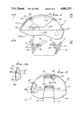
- FIG. 1 is a left side view of a helmet system incorporating the invention
- FIG. 2 is a rear elevation taken on lines 2--2 of FIG. 1;
- FIG. 2a is an enlarged fragmentary section on lines 2a--2a of FIG. 2, partly broken away to show interior construction
- FIG. 3 is a front elevation on lines 3--3 of FIG. 1, partly broken away to show detailed construction
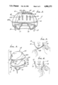
- FIG. 4 is a perspective exploded view showing liner and lightweight outer shell elements
- FIGS. 5 and 6 are front elevations showing the helmet retention system in tightening and loosening modes
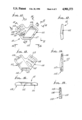
- FIG. 7 is an enlarged front (outer side) elevation showing a retention system left side junction plate
- FIG. 8 is a section in elevation on lines 8--8 of FIG. 7;
- FIG. 9 is a rear elevational view of the FIG. 7 clip
- FIG. 10 is an enlarged section taken on lines 10--10 of FIG. 7;
- FIG. 11 is an enlarged front (outer side) elevation showing a retention system right side junction plate
- FIG. 12 is a side elevation on lines 12--12 of FIG. 11;
- FIG. 13 is a rear elevation showing the FIG. 11 plate
- FIG. 14 is a section on lines 14--14 of FIG. 11;
- FIG. 15 is a section on lines 15--15 of FIG. 11;
- FIGS. 16-18 are views taken on lines 16--16, 17--17, and 18--18, respectively, of FIG. 11;
- FIG. 19 is a side elevation showing a selectively colored band applied to the helmet of FIGS. 1-3.
- FIG. 20 is a vertical section showing the retention system, viewed forwardly.
- FIGS. 4-6 show the provision of a retention system or harness for a lightweight helmet 11.
- the system comprises left and right retention strap sections 12 and 13 attached to the helmet forward extent 11a; left and right junction plates 14 and 15 (see FIGS. 7 and 11) respectively attached to the strap sections 12 and 13 (as illustrated in FIG. 1 for section 14); and rear strap sections 16 and 17 attached to the helmet rearward extent 11b.
- the plate 15 is shown shifted out of position, for visibility.
- the strap sections 12 and 13 extend upwardly and inwardly into the helmet upwardly domed interior, and then through perforations 60 and 61 in the helmet thicker shell 62, and extend across the outer upper side of that shell, in a lateral recess 63. See FIG. 3.
- the two strap sections merge together at 12a and 13a and are then joined.
- the rear strap sections 16 and 17 likewise extend upwardly and rearwardly into the helmet interior, and then through perforations 64 and 65 in the helmet shell 62, and extend across the outer rear side of the shell, in a lateral recess 66. See FIG. 2.
- the two strap sections merge together as at 16a, 17a and are then joined.
- a thin, very lightweight outer shell 69 (see FIG. 4) is fitted down over the dome 62a of shell 62, and attached in place, as by adhesive bonding, to cover the recesses 63 and 66 and the strap extents therein.
- FIGS. 2, 2a and 3 show the lower peripheral lip bead 69a on outer shell 69 fitted downwardly against stop or locating shoulder 70 provided or formed by the shell 62. Shoulder 70 extends in oval shape or loop configuration about the lower extent of the shell 69 and forms an upward facing ledge.
- first, second and third attachment structures 77-79 which are integrally interconnected, as by molding in the form of a one-piece plastic unit.
- Structure 77 includes multiple generally forwardly extending slots in which one of the left and right strap sections is threaded, for strap length adjustment and plate retention. Three such slots are shown at 81-83, extending in parallel relation, forwardly and downwardly, at angle ⁇ from horizontal. Angle ⁇ is between 30° and 40° (and preferably about 35°) to conform the strap to the helmet and to the face and jaw of the wearer, and also to accomodate functioning of the plate, to be described.
- FIG. 20 shows strap section 12 passing at 12a from the inside to the outside of upper slot 81, then downwardly and passing at 12b from the outside to the inside of middle slot 82, then passing downwardly and outwardly at 12c from the inside to the outside of lower slot 83; then passing upwardly and inwardly at 12d from the outside to the inside of upper slot 81; and then extending freely upwardly as a tab 12e, for finger gripping and adjustment.
- Slot 81 has sharp upper and inner edges at 81a and 81b to pinch strap portions 12a and 12d preventing slip. See also inner edges 82a and 83a to grip the strap.
- attachment structure 78 as exemplified by parallel slots 86-88 (corresponding in function and structure to slots 81-83), to retain strap section 16. Note sharp inner edges 86a, 87a and 88a to grip the strap, these edges corresponding to edges 81a, 82a and 83a. Slots 86-88 extend rearwardly and downwardly at angle ⁇ from horizontal, where ⁇ is between 30° and 40°, and is preferably about 35°.
- the third attachment structure 79 projects downwardly and defines two parallel through slots 90 and 91 that extend generally forwardly and rearwardly, one above the other. See FIG. 8.
- a cross piece 92 extends between and separates these two slots or openings, and it has a generally triangular cross section with narrow flats 93 and 94 at its upper and lower edges, and a sharp inwardly projected apex at 95. That apex terminates approximately mid-way between vertical planes defined by inner and outer faces 96 and 97 of the plate 14; thus, slots 90 and 91 merge in region 98, between faces 97 and 96, but closer to the latter. Note also horizontal upper guide surface 99 of slot 90, and upwardly and inwardly angled lower guide surface 100 of slot 91.
- Surface 100 is parallel to the lower surface 101 of the triangular cross piece, both extending at about 45° to horizontal, as shown. Angled lower and upper surfaces 101 and 102 of the cross-piece converge toward apex 95; angled surface 100 terminates at narrow flat 103. Flats 93, 94 and 103 have dual parallel sharp edges, as shown, providing six chin strap engaging and retention edges.
- strap 17 has looping portions 17a, 17b, and 17c that engage those six edges when strap section 17d is pulled in direction 107 to tighten the strap, holding plate 14 against the left side of the user's face.
- a glide ring 108 is attached to the end portion of strap section 17d, and passes the strap 17, to glide therealong, when the user grips end 17e, and pulls it in direction 107.
- the construction is such that when the plate is tilted outwardly away from the user's face and about fulcrum 104, and to a plane near that as is indicated at 14a, the edges of the narrow flats 93, 94 and 103 are sufficiently relieved from engagement with the strap loop or looping portions that the strap loosens automatically, and strap section 17d travels back toward the plate to an extent corresponding to such loosening, which corresponds to tilting of the plate, as described.
- a quick and ready adjustment of the chin strap tightness is achieved by the degree of easy manual tilting of the junction plate.
- Lower inner extent of the plate is relieved at 160, to provide an outstanding lower projection 161 which may be readily grasped by the user's fingers, to tilt the plate as described.
- FIGS. 1 and 11-16 show the right side junction plate 15 which has strap retention structures 110, 111 and 112.
- Structure 110 has the same slot construction as structure 77, and retains strap 13 in the same manner that structure 77 retains strap 12. See slots 113-115 of structure 110, like slots 81-83 of structure 77.
- Structure 111 has only one slot 116, corresponding for example to slot 86 of structure 78, and it simply passes strap 17, which then extends downwardly through in structure 112 as seen in FIG. 1. Strap 17 may extend to and through a suitable glide, as shown at 108 in FIG. 8, and at 108" in FIG. 20.
- the outer thin shell 69 contains or defines four vertical air inlet openings 170 which register with corresponding air inlet openings 171 in the front side of shell 62. (See FIGS. 1, 3, and 19). Likewise, the outer shell 69 contains or defines one horizontal and lateral air discharge opening 172 which registers with corresponding air discharge opening 173 in the rear wall of shell 62. Front to rear slots in the upper interior foam of shell 69 (and between broken lines 174 and 175 in FIG. 1) pass inlet air from inlet slots 170 and 171 to outlet slots 172 and 173, for ventillating purposes.
- the laterally exposed lower looping side wall extent 178 of shell 62 defines a looping, laterally outstanding surface to support a decorative band 180 (see FIG. 19 and FIG. 2a). That band extends in a loop, and is elastic to stretch over and cling to the side surface 178. Also, the band has an upper edge 181 fits over bead 69a of thin shell 69, for retaining the band in position; also, the lower edge of the band curls beneath the lower edge 178a of shell 62, to assist in retaining the band in position.
- the band and lower extent 178 are generally forwardly wedge shaped. Thus, the band hugs the shell 62 and becomes a part of the helmet.
- the helmet wearer can select which decorative band he may want to wear on his helmet, at any time, i.e. choose a band having a color to match his or her sports wear for that day, and replace the band with another of a different design or color, for a different occasion.
- This give the appearance effect of having a different helmet, one for each occasion, but without incurring the cost of a large number of complete helmets.
- Slide 108 may have one opening as seen, in FIG. 8, or two parallel elongated openings as seen at 108" in FIG. 20, to pass strap 17.
Landscapes
- Helmets And Other Head Coverings (AREA)
Abstract
Description
Claims (13)
Priority Applications (2)
| Application Number | Priority Date | Filing Date | Title |
|---|---|---|---|
| US07/164,852 US4901373A (en) | 1988-03-07 | 1988-03-07 | Helmet retention system with adjustable buckle |
| US07/668,728 US5123121A (en) | 1988-03-07 | 1991-03-13 | Helmet retention system with adjustable buckle |
Applications Claiming Priority (1)
| Application Number | Priority Date | Filing Date | Title |
|---|---|---|---|
| US07/164,852 US4901373A (en) | 1988-03-07 | 1988-03-07 | Helmet retention system with adjustable buckle |
Related Child Applications (1)
| Application Number | Title | Priority Date | Filing Date |
|---|---|---|---|
| US25546988A Division | 1988-03-07 | 1988-10-11 |
Publications (1)
| Publication Number | Publication Date |
|---|---|
| US4901373A true US4901373A (en) | 1990-02-20 |
Family
ID=22596355
Family Applications (1)
| Application Number | Title | Priority Date | Filing Date |
|---|---|---|---|
| US07/164,852 Expired - Fee Related US4901373A (en) | 1988-03-07 | 1988-03-07 | Helmet retention system with adjustable buckle |
Country Status (1)
| Country | Link |
|---|---|
| US (1) | US4901373A (en) |
Cited By (45)
| Publication number | Priority date | Publication date | Assignee | Title |
|---|---|---|---|---|
| US5010598A (en) * | 1988-06-20 | 1991-04-30 | Britax Child-Care Products Pty. Ltd. | Safety helmet |
| US5077839A (en) * | 1990-08-06 | 1992-01-07 | Illinois Tool Works Inc. | Helmet chain strap buckle |
| US5083320A (en) * | 1990-12-24 | 1992-01-28 | Athletic Helmet, Inc. | Protective helmet with self-contained air pump |
| US5123121A (en) * | 1988-03-07 | 1992-06-23 | Bell Helmets, Inc. | Helmet retention system with adjustable buckle |
| EP0497032A1 (en) * | 1991-01-29 | 1992-08-05 | Shoei Kako Kabushiki Kaisha | Helmet |
| EP0517091A1 (en) * | 1991-05-31 | 1992-12-09 | 6262 Quebec Inc 9001 | Protective headgear |
| WO1992008380A3 (en) * | 1990-11-20 | 1993-03-04 | Ontario Ltd 636729 | Protective headgear and detachable face protector |
| US5216786A (en) * | 1991-03-25 | 1993-06-08 | National Molding Corporation | Plastic buckle and method of forming thereof |
| EP0581460A1 (en) * | 1992-07-30 | 1994-02-02 | Britax Nordiska Barn AB | Bicycle helmet |
| US5298208A (en) * | 1991-11-01 | 1994-03-29 | Athletic Helmet, Inc. | Method for molding a protective helmet |
| US5351342A (en) * | 1992-02-03 | 1994-10-04 | Louis Garneau | Protective headgear |
| EP0619955A1 (en) * | 1993-04-13 | 1994-10-19 | E.D.C. Sàrl | Crash-helmet for cyclists and for non-motor sports in general |
| US5361953A (en) * | 1991-01-10 | 1994-11-08 | Shooting Systems Group, Inc. | Shoulder harness with connector piece |
| US5398390A (en) * | 1992-05-04 | 1995-03-21 | Zedel | Fixing loop for a chin-strap of a safety helmet |
| US5450631A (en) * | 1993-09-17 | 1995-09-19 | Specialized Bicycle Components, Inc. | Bicycle helmet |
| US5519895A (en) * | 1993-04-28 | 1996-05-28 | Barnes, Jr.; Montie M. | Cap for sports helmet |
| US5551094A (en) * | 1994-05-20 | 1996-09-03 | Michael V. Navone | Helmet retention system with adjustable headband |
| US5575017A (en) * | 1996-01-02 | 1996-11-19 | Rawlings Sporting Goods Company, Inc. | Adjustable baseball batter's helmet |
| EP0743022A2 (en) * | 1995-05-17 | 1996-11-20 | Hans-Georg Knauer | Helmet for cyclist and process for manufacturing the same |
| EP0769256A1 (en) * | 1995-10-18 | 1997-04-23 | 9001 6262 Quebec Inc | Protective headgear and abutment plate thereof |
| WO1997037553A1 (en) * | 1996-04-04 | 1997-10-16 | Rbr Armour Ltd. | Helmets |
| USD385663S (en) * | 1996-04-16 | 1997-10-28 | Rawlings Sporting Goods Company, Inc. | Catcher's cap |
| US5694649A (en) * | 1996-01-02 | 1997-12-09 | Rawlings Sporting Goods Company, Inc. | Adjustable baseball batter's and catcher's helmet with mask |
| US6128786A (en) * | 1997-10-16 | 2000-10-10 | Hos Development Corporation | One-size-fits-all helmet |
| US6159324A (en) * | 1999-03-05 | 2000-12-12 | Sportscope | Process for manufacturing protective helmets |
| US6292952B1 (en) | 1998-09-25 | 2001-09-25 | Sportscope, Inc. | Insert-molded helmet |
| US20060026742A1 (en) * | 2004-08-03 | 2006-02-09 | Arne Lang-Ree | Helmet protection system |
| EP1714569A1 (en) | 2005-04-20 | 2006-10-25 | Specialized Bicycle Components, Inc. | Bicycle helmet |
| WO2006114514A1 (en) * | 2005-04-25 | 2006-11-02 | Msa Gallet | Improvement for the retaining means of a protective helmet |
| US20070050895A1 (en) * | 2004-10-22 | 2007-03-08 | Broersma Lester V | Monolithic paintball mask |
| US20070277295A1 (en) * | 2006-05-19 | 2007-12-06 | Christopher Bullock | Bicycle helmet with reinforcement structure |
| US20070277296A1 (en) * | 2006-05-19 | 2007-12-06 | Christopher Bullock | Bicycle helmet with reinforcement structure |
| US20090055999A1 (en) * | 2007-08-29 | 2009-03-05 | Troxel. Llc | Chin strap retainer ring for headgear |
| US7681257B1 (en) | 2005-11-29 | 2010-03-23 | Jt Sports, Llc | Rotating lens locking device |
| US20130065486A1 (en) * | 2011-09-08 | 2013-03-14 | Doris Hjorth Hansen | Post-operative brassiere |
| USD679865S1 (en) | 2010-05-17 | 2013-04-09 | Louis Garneau Sports Inc. | Helmet |
| US8438668B2 (en) | 2010-05-17 | 2013-05-14 | Louis Garneau Sports Inc. | Occipital stabilization strap for helmets |
| US20130152281A1 (en) * | 2011-12-19 | 2013-06-20 | Scott G. Kravitz | Chin protection system |
| US9370215B1 (en) * | 2012-03-08 | 2016-06-21 | Protective Sports Equipment International Inc | Helmet cover |
| US9681692B2 (en) | 2015-06-26 | 2017-06-20 | Qualiteam S.R.L. | Post-operative sternum and breast device |
| US20170295882A1 (en) * | 2014-10-09 | 2017-10-19 | Artisent, Llc | Individually Conforming Impact Attenuating Liner for a Helmet |
| US20180192730A1 (en) * | 2015-07-07 | 2018-07-12 | Headkayse Ltd. | A Helmet |
| US20180317588A1 (en) * | 2017-05-08 | 2018-11-08 | Bell Sports, Inc. | Truncated helmet |
| US20180325204A1 (en) * | 2014-03-07 | 2018-11-15 | Bell Sports, Inc. | Multi-body helmet construction and strap attachment method |
| USD979453S1 (en) * | 2020-12-18 | 2023-02-28 | Lindarets, LLC | Buckle |
Citations (17)
| Publication number | Priority date | Publication date | Assignee | Title |
|---|---|---|---|---|
| US1440403A (en) * | 1921-10-15 | 1923-01-02 | Goldsmith S Sons P | Strap slide buckle |
| US2316846A (en) * | 1942-04-27 | 1943-04-20 | George L Diebold | Adjustable strap fastener |
| US3146462A (en) * | 1962-07-02 | 1964-09-01 | American Allsafe Co | Cold weather attachment for hard head gear |
| US3192588A (en) * | 1962-02-21 | 1965-07-06 | Parva Products Co | Buckle |
| US3336639A (en) * | 1964-10-27 | 1967-08-22 | Stanley Works | Strap buckle |
| US3501772A (en) * | 1968-05-08 | 1970-03-24 | Sierra Eng Co | Sporting safety helmet |
| US4044400A (en) * | 1976-10-18 | 1977-08-30 | Bell Helmets Inc. | Helmet retention system |
| US4171555A (en) * | 1978-05-01 | 1979-10-23 | Illinois Tool Works Inc. | Buckle |
| US4279037A (en) * | 1968-08-02 | 1981-07-21 | Morgan Frank S | Adjustable headgear suspension |
| US4387490A (en) * | 1980-07-15 | 1983-06-14 | Itw Limited | Buckles |
| US4395803A (en) * | 1981-04-06 | 1983-08-02 | American Cord & Webbing Co., Inc. | Buckle |
| US4445253A (en) * | 1982-06-21 | 1984-05-01 | Howey Thomas L | Quick release helmet and strap assembly |
| US4461044A (en) * | 1982-06-04 | 1984-07-24 | Bell Helmets Inc. | Bicycle helmet retention system with quick disconnect |
| US4525901A (en) * | 1983-11-23 | 1985-07-02 | American Cord & Webbing Co., Inc. | Buckle having improved web securement |
| US4571783A (en) * | 1983-12-20 | 1986-02-25 | Nippon Notion Kogyo Co., Ltd. | Adjustable strap fastener |
| US4622700A (en) * | 1985-12-09 | 1986-11-18 | Bell Helmets Inc. | Suction ventilated helmet |
| US4637099A (en) * | 1984-12-26 | 1987-01-20 | Nippon Notion Kogyo Co., Ltd. | Adjustable strap fastener |
-
1988
- 1988-03-07 US US07/164,852 patent/US4901373A/en not_active Expired - Fee Related
Patent Citations (17)
| Publication number | Priority date | Publication date | Assignee | Title |
|---|---|---|---|---|
| US1440403A (en) * | 1921-10-15 | 1923-01-02 | Goldsmith S Sons P | Strap slide buckle |
| US2316846A (en) * | 1942-04-27 | 1943-04-20 | George L Diebold | Adjustable strap fastener |
| US3192588A (en) * | 1962-02-21 | 1965-07-06 | Parva Products Co | Buckle |
| US3146462A (en) * | 1962-07-02 | 1964-09-01 | American Allsafe Co | Cold weather attachment for hard head gear |
| US3336639A (en) * | 1964-10-27 | 1967-08-22 | Stanley Works | Strap buckle |
| US3501772A (en) * | 1968-05-08 | 1970-03-24 | Sierra Eng Co | Sporting safety helmet |
| US4279037A (en) * | 1968-08-02 | 1981-07-21 | Morgan Frank S | Adjustable headgear suspension |
| US4044400A (en) * | 1976-10-18 | 1977-08-30 | Bell Helmets Inc. | Helmet retention system |
| US4171555A (en) * | 1978-05-01 | 1979-10-23 | Illinois Tool Works Inc. | Buckle |
| US4387490A (en) * | 1980-07-15 | 1983-06-14 | Itw Limited | Buckles |
| US4395803A (en) * | 1981-04-06 | 1983-08-02 | American Cord & Webbing Co., Inc. | Buckle |
| US4461044A (en) * | 1982-06-04 | 1984-07-24 | Bell Helmets Inc. | Bicycle helmet retention system with quick disconnect |
| US4445253A (en) * | 1982-06-21 | 1984-05-01 | Howey Thomas L | Quick release helmet and strap assembly |
| US4525901A (en) * | 1983-11-23 | 1985-07-02 | American Cord & Webbing Co., Inc. | Buckle having improved web securement |
| US4571783A (en) * | 1983-12-20 | 1986-02-25 | Nippon Notion Kogyo Co., Ltd. | Adjustable strap fastener |
| US4637099A (en) * | 1984-12-26 | 1987-01-20 | Nippon Notion Kogyo Co., Ltd. | Adjustable strap fastener |
| US4622700A (en) * | 1985-12-09 | 1986-11-18 | Bell Helmets Inc. | Suction ventilated helmet |
Cited By (67)
| Publication number | Priority date | Publication date | Assignee | Title |
|---|---|---|---|---|
| US5123121A (en) * | 1988-03-07 | 1992-06-23 | Bell Helmets, Inc. | Helmet retention system with adjustable buckle |
| US5010598A (en) * | 1988-06-20 | 1991-04-30 | Britax Child-Care Products Pty. Ltd. | Safety helmet |
| US5077839A (en) * | 1990-08-06 | 1992-01-07 | Illinois Tool Works Inc. | Helmet chain strap buckle |
| WO1992008380A3 (en) * | 1990-11-20 | 1993-03-04 | Ontario Ltd 636729 | Protective headgear and detachable face protector |
| US5083320A (en) * | 1990-12-24 | 1992-01-28 | Athletic Helmet, Inc. | Protective helmet with self-contained air pump |
| US5361953A (en) * | 1991-01-10 | 1994-11-08 | Shooting Systems Group, Inc. | Shoulder harness with connector piece |
| EP0497032A1 (en) * | 1991-01-29 | 1992-08-05 | Shoei Kako Kabushiki Kaisha | Helmet |
| US5272773A (en) * | 1991-01-29 | 1993-12-28 | Shoei Kako Kabushiki Kaisha | Helmet |
| US5216786A (en) * | 1991-03-25 | 1993-06-08 | National Molding Corporation | Plastic buckle and method of forming thereof |
| EP0517091A1 (en) * | 1991-05-31 | 1992-12-09 | 6262 Quebec Inc 9001 | Protective headgear |
| US5298208A (en) * | 1991-11-01 | 1994-03-29 | Athletic Helmet, Inc. | Method for molding a protective helmet |
| EP0618773A1 (en) * | 1991-11-01 | 1994-10-12 | Athletic Helmet, Inc. | Protective helmet and method and apparatus for molding same |
| EP0618773A4 (en) * | 1991-11-01 | 1995-01-25 | Athletic Helmet Inc | Protective helmet and method and apparatus for molding same. |
| US5351342A (en) * | 1992-02-03 | 1994-10-04 | Louis Garneau | Protective headgear |
| US5398390A (en) * | 1992-05-04 | 1995-03-21 | Zedel | Fixing loop for a chin-strap of a safety helmet |
| EP0581460A1 (en) * | 1992-07-30 | 1994-02-02 | Britax Nordiska Barn AB | Bicycle helmet |
| EP0619955A1 (en) * | 1993-04-13 | 1994-10-19 | E.D.C. Sàrl | Crash-helmet for cyclists and for non-motor sports in general |
| US5519895A (en) * | 1993-04-28 | 1996-05-28 | Barnes, Jr.; Montie M. | Cap for sports helmet |
| US5745924A (en) * | 1993-09-17 | 1998-05-05 | Specialized Bicycle Components, Inc. | Bicycle helmet |
| US5450631A (en) * | 1993-09-17 | 1995-09-19 | Specialized Bicycle Components, Inc. | Bicycle helmet |
| US6105176A (en) * | 1993-09-17 | 2000-08-22 | Specialized Bicycle Components, Inc. | Bicycle helmet |
| US5651145A (en) * | 1993-09-17 | 1997-07-29 | Specialized Bicycle Components, Inc. | Bicycle helmet |
| US5813055A (en) * | 1993-09-17 | 1998-09-29 | Specialized Bicycle Components, Inc. | Bicycle helmet |
| US5551094A (en) * | 1994-05-20 | 1996-09-03 | Michael V. Navone | Helmet retention system with adjustable headband |
| EP0743022A2 (en) * | 1995-05-17 | 1996-11-20 | Hans-Georg Knauer | Helmet for cyclist and process for manufacturing the same |
| EP0743022A3 (en) * | 1995-05-17 | 1998-12-02 | Hans-Georg Knauer | Helmet for cyclist and process for manufacturing the same |
| EP0769256A1 (en) * | 1995-10-18 | 1997-04-23 | 9001 6262 Quebec Inc | Protective headgear and abutment plate thereof |
| US5694649A (en) * | 1996-01-02 | 1997-12-09 | Rawlings Sporting Goods Company, Inc. | Adjustable baseball batter's and catcher's helmet with mask |
| US5575017A (en) * | 1996-01-02 | 1996-11-19 | Rawlings Sporting Goods Company, Inc. | Adjustable baseball batter's helmet |
| WO1997037553A1 (en) * | 1996-04-04 | 1997-10-16 | Rbr Armour Ltd. | Helmets |
| USD385663S (en) * | 1996-04-16 | 1997-10-28 | Rawlings Sporting Goods Company, Inc. | Catcher's cap |
| US6128786A (en) * | 1997-10-16 | 2000-10-10 | Hos Development Corporation | One-size-fits-all helmet |
| US6292952B1 (en) | 1998-09-25 | 2001-09-25 | Sportscope, Inc. | Insert-molded helmet |
| US6532602B2 (en) | 1998-09-25 | 2003-03-18 | Sportscope, Inc. | Insert-molded helmet |
| EP1435804A4 (en) * | 1998-09-25 | 2004-07-14 | Sportscope Inc | Insert-molded helmet |
| EP1435804A2 (en) * | 1998-09-25 | 2004-07-14 | Sportscope, Inc. | Insert-molded helmet |
| US6159324A (en) * | 1999-03-05 | 2000-12-12 | Sportscope | Process for manufacturing protective helmets |
| US7140049B2 (en) * | 2004-08-03 | 2006-11-28 | Bell Sports, Inc. | Helmet protection system |
| US20060026742A1 (en) * | 2004-08-03 | 2006-02-09 | Arne Lang-Ree | Helmet protection system |
| US20070050895A1 (en) * | 2004-10-22 | 2007-03-08 | Broersma Lester V | Monolithic paintball mask |
| US20060248630A1 (en) * | 2005-04-20 | 2006-11-09 | Christopher Bullock | Bicycle helmet |
| US7376980B2 (en) | 2005-04-20 | 2008-05-27 | Specialized Bicycle Components, Inc. | Bicycle helmet |
| EP1714569A1 (en) | 2005-04-20 | 2006-10-25 | Specialized Bicycle Components, Inc. | Bicycle helmet |
| WO2006114514A1 (en) * | 2005-04-25 | 2006-11-02 | Msa Gallet | Improvement for the retaining means of a protective helmet |
| FR2901969A1 (en) * | 2005-04-25 | 2007-12-14 | Msa Gallet Sa | IMPROVEMENT FOR MEANS FOR MAINTAINING A PROTECTIVE HELMET |
| US7681257B1 (en) | 2005-11-29 | 2010-03-23 | Jt Sports, Llc | Rotating lens locking device |
| US7698750B2 (en) | 2006-05-19 | 2010-04-20 | Specialized Bicycle Components, Inc. | Bicycle helmet with reinforcement structure |
| US20070277296A1 (en) * | 2006-05-19 | 2007-12-06 | Christopher Bullock | Bicycle helmet with reinforcement structure |
| US20070277295A1 (en) * | 2006-05-19 | 2007-12-06 | Christopher Bullock | Bicycle helmet with reinforcement structure |
| US7913325B2 (en) | 2006-05-19 | 2011-03-29 | Specialized Bicycle Components, Inc. | Bicycle helmet with reinforcement structure |
| US20090055999A1 (en) * | 2007-08-29 | 2009-03-05 | Troxel. Llc | Chin strap retainer ring for headgear |
| US8438668B2 (en) | 2010-05-17 | 2013-05-14 | Louis Garneau Sports Inc. | Occipital stabilization strap for helmets |
| USD679865S1 (en) | 2010-05-17 | 2013-04-09 | Louis Garneau Sports Inc. | Helmet |
| US8932103B2 (en) * | 2011-09-08 | 2015-01-13 | Doris Hjorth Hansen | Post-operative brassiere |
| US20130065486A1 (en) * | 2011-09-08 | 2013-03-14 | Doris Hjorth Hansen | Post-operative brassiere |
| US20130152281A1 (en) * | 2011-12-19 | 2013-06-20 | Scott G. Kravitz | Chin protection system |
| US9370215B1 (en) * | 2012-03-08 | 2016-06-21 | Protective Sports Equipment International Inc | Helmet cover |
| US20180325204A1 (en) * | 2014-03-07 | 2018-11-15 | Bell Sports, Inc. | Multi-body helmet construction and strap attachment method |
| US10881161B2 (en) * | 2014-03-07 | 2021-01-05 | Bell Sports, Inc. | Multi-body helmet construction and strap attachment method |
| US20170295882A1 (en) * | 2014-10-09 | 2017-10-19 | Artisent, Llc | Individually Conforming Impact Attenuating Liner for a Helmet |
| US10893718B2 (en) * | 2014-10-09 | 2021-01-19 | Gentex Corporation | Individually conforming impact attenuating liner for a helmet |
| US9681692B2 (en) | 2015-06-26 | 2017-06-20 | Qualiteam S.R.L. | Post-operative sternum and breast device |
| US10791789B2 (en) * | 2015-07-07 | 2020-10-06 | Headkayse Ltd | Helmet |
| US20180192730A1 (en) * | 2015-07-07 | 2018-07-12 | Headkayse Ltd. | A Helmet |
| US10575582B2 (en) * | 2017-05-08 | 2020-03-03 | Bell Sports, Inc. | Truncated helmet |
| US20180317588A1 (en) * | 2017-05-08 | 2018-11-08 | Bell Sports, Inc. | Truncated helmet |
| USD979453S1 (en) * | 2020-12-18 | 2023-02-28 | Lindarets, LLC | Buckle |
Similar Documents
| Publication | Publication Date | Title |
|---|---|---|
| US4901373A (en) | Helmet retention system with adjustable buckle | |
| US5123121A (en) | Helmet retention system with adjustable buckle | |
| US4653123A (en) | Aerodynamic bicyclist's helmet construction | |
| US5581819A (en) | Protective headgear and abutment plate thereof | |
| US4888831A (en) | Adjustable head band suspension system for use with hard hat shell | |
| US5704072A (en) | Occipital retention strap for cyclist headgear | |
| US5794272A (en) | Protective helmet with improved retention system having a rear stabilizer | |
| US5815847A (en) | One size fits all baseball batter's helmet | |
| US5659900A (en) | Sizing and stabilizing apparatus for bicycle helmets | |
| US5437062A (en) | Baseball cap with detachable visor | |
| US10219577B1 (en) | Integrated fit and retention system | |
| US4686712A (en) | Goggle mounting system | |
| US5774901A (en) | Sport helmet retention apparatus | |
| US5598585A (en) | Headband with ponytail holder | |
| US4897888A (en) | Helmet strap clip, and assembly | |
| US6311338B1 (en) | Arrangement for maintaining a protective helmet | |
| US3619813A (en) | Helmet chin strap | |
| US4884301A (en) | Combination chinstrap-napestrap assembly for helmet | |
| US6952841B2 (en) | Sports goggles | |
| US9681695B2 (en) | Helmet with chin cup | |
| US7765621B2 (en) | Removable modular padding for protective helmet and helmet equipped therewith | |
| ITTO960798A1 (en) | DEVICE TO ADAPT AND FIX A HELMET TO THE USER'S HEAD. | |
| US20150128979A1 (en) | Wig cap | |
| US20060180154A1 (en) | Apparatus for attaching a hydration device to a full face helmet | |
| WO1990009609A1 (en) | Eyewear retainer |
Legal Events
| Date | Code | Title | Description |
|---|---|---|---|
| AS | Assignment |
Owner name: BELL HELMETS, INC., 150301 SHOEMAKER AVENUE, NORWA Free format text: ASSIGNMENT OF ASSIGNORS INTEREST.;ASSIGNOR:BROERSMA, LESTER V.;REEL/FRAME:004877/0855 Effective date: 19880218 Owner name: BELL HELMETS, INC., A CA CORP., CALIFORNIA Free format text: ASSIGNMENT OF ASSIGNORS INTEREST;ASSIGNOR:BROERSMA, LESTER V.;REEL/FRAME:004877/0855 Effective date: 19880218 |
|
| REMI | Maintenance fee reminder mailed | ||
| LAPS | Lapse for failure to pay maintenance fees | ||
| FP | Lapsed due to failure to pay maintenance fee |
Effective date: 19930220 |
|
| STCH | Information on status: patent discontinuation |
Free format text: PATENT EXPIRED DUE TO NONPAYMENT OF MAINTENANCE FEES UNDER 37 CFR 1.362 |