EP0567861A1 - Methode und System zur Kontrolle des Bremsdruckes bei "tiefer Mu Bremsfläche" (Fläche mit einem tiefen Reibungskoeffizienten)-Bedingungen in einem Fahrzeug-ABS - Google Patents
Methode und System zur Kontrolle des Bremsdruckes bei "tiefer Mu Bremsfläche" (Fläche mit einem tiefen Reibungskoeffizienten)-Bedingungen in einem Fahrzeug-ABS Download PDFInfo
- Publication number
- EP0567861A1 EP0567861A1 EP93106179A EP93106179A EP0567861A1 EP 0567861 A1 EP0567861 A1 EP 0567861A1 EP 93106179 A EP93106179 A EP 93106179A EP 93106179 A EP93106179 A EP 93106179A EP 0567861 A1 EP0567861 A1 EP 0567861A1
- Authority
- EP
- European Patent Office
- Prior art keywords
- speed
- vehicle
- reference speed
- wheels
- wheel
- Prior art date
- Legal status (The legal status is an assumption and is not a legal conclusion. Google has not performed a legal analysis and makes no representation as to the accuracy of the status listed.)
- Granted
Links
- 238000000034 method Methods 0.000 title claims abstract description 21
- 230000003247 decreasing effect Effects 0.000 claims description 11
- 238000012544 monitoring process Methods 0.000 claims description 4
- 230000001133 acceleration Effects 0.000 abstract description 11
- 239000012530 fluid Substances 0.000 description 4
- 230000000694 effects Effects 0.000 description 3
- 125000004122 cyclic group Chemical group 0.000 description 2
- 238000010586 diagram Methods 0.000 description 2
- 238000012937 correction Methods 0.000 description 1
- 239000000463 material Substances 0.000 description 1
- 238000012545 processing Methods 0.000 description 1
- 230000000717 retained effect Effects 0.000 description 1
- 238000005096 rolling process Methods 0.000 description 1
Images


Classifications
-
- B—PERFORMING OPERATIONS; TRANSPORTING
- B60—VEHICLES IN GENERAL
- B60T—VEHICLE BRAKE CONTROL SYSTEMS OR PARTS THEREOF; BRAKE CONTROL SYSTEMS OR PARTS THEREOF, IN GENERAL; ARRANGEMENT OF BRAKING ELEMENTS ON VEHICLES IN GENERAL; PORTABLE DEVICES FOR PREVENTING UNWANTED MOVEMENT OF VEHICLES; VEHICLE MODIFICATIONS TO FACILITATE COOLING OF BRAKES
- B60T8/00—Arrangements for adjusting wheel-braking force to meet varying vehicular or ground-surface conditions, e.g. limiting or varying distribution of braking force
- B60T8/17—Using electrical or electronic regulation means to control braking
- B60T8/176—Brake regulation specially adapted to prevent excessive wheel slip during vehicle deceleration, e.g. ABS
- B60T8/1763—Brake regulation specially adapted to prevent excessive wheel slip during vehicle deceleration, e.g. ABS responsive to the coefficient of friction between the wheels and the ground surface
- B60T8/17636—Microprocessor-based systems
Definitions
- This invention relates to a control method and system for use in a vehicular ABS which compensates for low Mu braking surfaces.
- truck brakes are designed to have the capacity of stopping a vehicle loaded to 20,000 lbs. per axle, they are extremely over-braked while operating empty on slippery roads. Even with ABS operation under these conditions small changes in brake pressure can have a large effect on wheel deceleration and may cause the wheels to be over-braked.
- the wheel speed shown in FIGURE 1 indicates the effect of this over-braking. Wheel speed control to the reference speed is very poor, producing vehicle stability problems and long stopping distances.
- the Y-axis is a multiple scale axis which represents speed in MPH, acceleration in units of g's (X 10), and numeric value of the ABS logic state. As the logic state on the Y-axis increases, the brake pressure rise rate increases.
- the X-axis is real time shown in milliseconds, usually ranging from 0 to 6. The acquisition of data is automatically started by the occurrence of a wheel deceleration rate which exceeds the allowable limit, based on vehicle reference speed. The plot contains 0.25 seconds of data prior to the start of the ABS event.
- wheel speed There are four types of data plotted: wheel speed, wheel acceleration, vehicle reference speed and the ABS logic state.
- the wheel speed data can be identified by its typical cyclic behavior modulating between the actual vehicle speed and the vehicle reference speed. Wheel accelerations correspond to the changes in wheel speed.
- the reference speed is calculated by subtracting 4 mph from the highest wheel speed and then taking 80% of the result. The reference speed is then decreased at a rate of -0.8 g's until it is recalculated by a higher wheel speed, when data is received.
- the behavior of the reference speed is typically much less cyclic than the wheel speeds as noted in the plot.
- the logic states are plotted using triangular markers placed at the Y-axis position corresponding to the numeric value logic state.
- the wheel speeds should be controlled to the reference speed.
- vehicle stability is decreased.
- the stopping distance may increase. It is important to maintain an accurate reference speed so the proper decisions can be made in controlling the wheel speeds. This becomes a tradeoff of stopping distance because the wheel is free-rolling in order to establish the true vehicle speed.
- the root of the control problem is typically in the control logic.
- Typical control logic can be found in the U.S. Patent to McNisch, Jr., 5,071,200.
- the data of FIGURE 1 indicates that the ABS logic recognizes that the wheel is decelerating and signals the ABS valve to release brake pressure. Because of the response time of the brake system, the wheel is over-braked. During the Release state, brake torque or pressure is reduced until the wheel starts to accelerate. The control logic then calls for a Hold state on brake pressure until the wheel speed reaches the vehicle reference speed. The wheel acceleration, at the time the wheel pressure exceeds the reference speed, determines how fast brake pressure will be reapplied.
- the data further indicates high acceleration levels, up to 6 G's, which, according to the logic, calls for fast pressure application rates.
- the wheel is again over-braked and the process is repeated, creating an unstable system.
- An object of the present invention is to provide a method and system for improving ABS performance by increasing vehicle stability and reducing stopping distances on very low Mu surfaces such as ice, without affecting performance on high Mu surfaces.
- a method for controlling brake pressure rise rate under low Mu braking surface conditions in a vehicular ABS.
- the vehicular ABS includes an ABS valve having variable pressure rise rates, the method includes the steps of monitoring the speed of the vehicle wheels and generating a vehicle reference speed based on the highest wheel speed of the vehicle.
- the method also includes the steps of decreasing the value of the vehicle reference speed over time and determining when the speed of one of the wheels is greater than the vehicle reference speed after the step of decreasing.
- the method further includes the steps of correcting the vehicle reference speed when the speed of the one of the wheels is greater than the vehicle reference speed and limiting the pressure rise rate when the speed of the one of the wheels is greater than the vehicle reference speed.
- the wheel is a front wheel of the vehicle.
- the bleed rate is fixed.
- FIGURE 2 there is illustrated a vehicular ABS of the type including an ABS valve 10 connected in series between a treadle valve 12 and at least one fluid pressure operated vehicle brake actuator for applying and releasing vehicular brakes 14.
- the ABS valve 10 is controlled by an electronic control unit (E.C.U.) 16 which receives a rotational speed signal along line 18 from an ABS wheel speed sensor 20 associated with each vehicular brake 14.
- the sensor 20 may be generally of the type illustrated in U.S. Patent No. 4,862,025 in the name of Dierker et al.
- control unit 16 determines a control parameter indicative of rotational acceleration of at least one vehicle wheel.
- the control unit 16 includes predetermined logic rules for processing the rotational speed signal and the acceleration control parameter and for issuing command output signals to the ABS valve.
- the ABS valve 10 has a relatively fast fill position wherein substantially all pressurized fluid from treadle valve 12 is passed to the brake actuators 14.
- the ABS valve 20 also has a relatively slow fill position wherein a reduced modulated amount of pressurized fluid is passed to the brake actuators 14.
- the ABS valve 10 has an exhaust position wherein fluid pressure acting on the brake actuators 14 is exhausted to cause release of the vehicular brakes 14.
- the control unit 16 is effective upon sensing conditions indicative of an actual or incipient wheel-lock condition to cause the ABS valve 10 to assume the exhaust position.
- the ABS control logic within the control unit 16 is based on monitoring the wheel speeds, if a wheel is decelerating beyond a predetermined threshold reduce brake pressure, and increase brake pressure if the acceleration or speed is above predetermined threshold. Wheel speed information is obtained every 10 ms and wheel accelerations are then calculated. The logic then determines which of the four states of brake control, (APPLY, RAMP, HOLD, RELEASE) should be implemented and the corresponding duty cycle is output to the ABS valve 10.
- ABS system The key to determining if an ABS system will be effective in maintaining vehicle stability is to insure that under conditions which induce the most extreme wheel deceleration rates, the ABS system is capable of controlling wheel speeds to the optimum level. This optimum level is called the reference speed and is generally agreed upon to be approximately 80% of the true vehicle speed.
- FIGURE 3 Shown in FIGURE 3 is a typical ⁇ -slip curve for a rubber tire. It describes graphically the interface between the tires of a vehicle and the road. The lateral and longitudinal forces are given by ⁇ N where N is the normal (vertical) force applied at each wheel.
- the purpose of ABS operation is to control wheel slip so as to keep the wheels at a desired operation point on the ⁇ -slip curve.
- Minimum stopping distance can be achieved by holding a value of wheel slip which corresponds to the peak of the ⁇ -slip curve. In most cases the stopping distances achieved will be shorter than if the wheels were allowed to lock. In the case of gravel and snow, stopping distances may be shorter when the wheels lock because the loose material "piles up" in front of the tires.
- an important aspect of the ABS control logic is the determination of the reference speed. If the reference speed is incorrectly determined, the wheels will be improperly braked, resulting in reduced vehicle stability or extending stopping distances. Since there are no additional vehicle speed inputs to the ABS ECU 16 other than the speed of the wheels being braked, the reference speed has to be determined by releasing the brakes 18 and allowing the wheels to roll back to the true vehicle speed.
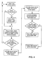
- FIGURE 4 The principle of operation of the logic of the present method and system of the invention is illustrated in FIGURE 4.
- the method and system use the front wheel reference speed to recognize that the vehicle is being over-braked on a low Mu surface.
- the front wheel speeds are used as the reference speed for a number of reasons. First, they are always loaded from the normal forces of the engine and cab. Secondly, because of the reduced mass and lower inertia when compared to drive axle speeds, they roll back to true vehicle speed faster than drive axle wheels if they are over-braking.
- wheel speed information is received every 10 ms.
- the vehicle reference speed is predicted from the highest known wheel speed or the value of the previously known highest wheel speed which is continuously being reduced at a rate of -0.8 g's until an actual wheel speed is measured above this value.
- the wheel decelerates faster than -0.8 g's, but the true vehicle speed does not. Therefore, when the brakes are released and the wheel rolls back up to the true vehicle speed, the predicted vehicle speed based on the fixed bleed rate is found to be in error, a correction is made which causes the vehicle reference speed to be stepped up by x amount.
- the amount x is equal to the error between the vehicle speed calculated from the actual wheel speed and the predicted vehicle speed from the fixed bleed rate.
- the brake pressure rise rate is restricted which reduces the over-braking and improves the ABS control.
- the brake pressure rise rate is a factor of many variables including the amount of treadle pressure the driver is supplying.
- the logic of the present invention compensates for this because it uses the actual wheel speed behavior to determine over-braking. This logic does not affect operation on high Mu braking surfaces because the predicted and actual vehicle reference speeds do not differ by more than the x amount.
- FIGURES 5 and 6 which are similar in form to FIGURE 1
- FIGURES 5 and 6 there is graphically illustrated wheel speed data which indicate excellent wheel speed control through the use of the present invention. From the data it is evident that after the first wheel speed dip the Apply state limits brake pressure rise rates to obtain this type of wheel behavior.
Landscapes
- Engineering & Computer Science (AREA)
- Transportation (AREA)
- Mechanical Engineering (AREA)
- Microelectronics & Electronic Packaging (AREA)
- Regulating Braking Force (AREA)
Applications Claiming Priority (2)
| Application Number | Priority Date | Filing Date | Title |
|---|---|---|---|
| US07/875,996 US5328254A (en) | 1992-04-29 | 1992-04-29 | Method and system for controlling brake pressure under low Mu braking surface conditions in a vehicular ABS |
| US875996 | 1992-04-29 |
Publications (2)
| Publication Number | Publication Date |
|---|---|
| EP0567861A1 true EP0567861A1 (de) | 1993-11-03 |
| EP0567861B1 EP0567861B1 (de) | 1996-01-24 |
Family
ID=25366742
Family Applications (1)
| Application Number | Title | Priority Date | Filing Date |
|---|---|---|---|
| EP93106179A Expired - Lifetime EP0567861B1 (de) | 1992-04-29 | 1993-04-16 | Methode und System zur Kontrolle des Bremsdruckes bei "tiefer Mu Bremsfläche" (Fläche mit einem tiefen Reibungskoeffizienten)-Bedingungen in einem Fahrzeug-ABS |
Country Status (10)
| Country | Link |
|---|---|
| US (1) | US5328254A (de) |
| EP (1) | EP0567861B1 (de) |
| JP (1) | JPH0624321A (de) |
| KR (1) | KR930021477A (de) |
| AU (1) | AU664960B2 (de) |
| BR (1) | BR9301024A (de) |
| CA (1) | CA2094956C (de) |
| DE (1) | DE69301370T2 (de) |
| ES (1) | ES2083218T3 (de) |
| MX (1) | MX9302504A (de) |
Cited By (2)
| Publication number | Priority date | Publication date | Assignee | Title |
|---|---|---|---|---|
| EP0770528A2 (de) * | 1995-10-25 | 1997-05-02 | Toyota Jidosha Kabushiki Kaisha | Einrichtung zur Stabilitätsregelung eines für manuellen Bremsbeginn nach Ende der Stabilitätsregelung vorbereiteten Fahrzeuges |
| WO1999000280A1 (en) * | 1997-06-27 | 1999-01-07 | Kelsey-Hayes Company | Algorithm for scheduling extra reapply pulses in a rear wheel anti-lock brake system |
Families Citing this family (2)
| Publication number | Priority date | Publication date | Assignee | Title |
|---|---|---|---|---|
| JP3869028B2 (ja) * | 1995-04-28 | 2007-01-17 | 日産自動車株式会社 | ブレーキ液圧制御装置 |
| AU2209399A (en) * | 1997-12-30 | 1999-07-19 | Kelsey-Hayes Company | Algorithm for preventing wheel speed sneakdown on a low mu surface |
Citations (8)
| Publication number | Priority date | Publication date | Assignee | Title |
|---|---|---|---|---|
| GB2171161A (en) * | 1985-02-19 | 1986-08-20 | Kelsey Hayes Co | Vehicle skid control system |
| US4787683A (en) * | 1987-09-11 | 1988-11-29 | Allied-Signal Inc. | Electro-pneumatic braking system with deceleration control |
| GB2229503A (en) * | 1988-12-13 | 1990-09-26 | Kelsey Hayes Co | Vehicle anti-lock brake system |
| GB2242490A (en) * | 1987-06-15 | 1991-10-02 | Kelsey Hayes Co | Improvements in and relating to anti-look brake system |
| GB2242492A (en) * | 1987-06-15 | 1991-10-02 | Kelsey Hayes Co | Improvements in and relating to anti-lock brake systems |
| US5071200A (en) * | 1989-10-12 | 1991-12-10 | Eaton Corporation | Abs pressure reapply logic |
| US5125723A (en) * | 1989-11-10 | 1992-06-30 | Tokico Ltd. | Antilock brake control apparatus |
| GB2252372A (en) * | 1990-12-17 | 1992-08-05 | Teves Gmbh Alfred | Circuit arrangement for an anti-lock brake system |
Family Cites Families (14)
| Publication number | Priority date | Publication date | Assignee | Title |
|---|---|---|---|---|
| JPS5519779B2 (de) * | 1971-09-29 | 1980-05-28 | ||
| DE2231166C2 (de) * | 1972-06-26 | 1985-02-14 | Robert Bosch Gmbh, 7000 Stuttgart | Antiblockierregelsystem für druckmittelbetätigte Fahrzeugbremsen |
| DE2527471C2 (de) * | 1975-06-20 | 1986-09-18 | Robert Bosch Gmbh, 7000 Stuttgart | Antiblockierregelsystem für eine Fahrzeugbremsanlage |
| DE3536185A1 (de) * | 1985-10-10 | 1987-04-23 | Daimler Benz Ag | Einrichtung zur generierung einer fuer die fahrgeschwindigkeit eines kraftfahrzeuges mit automatisch zu- und abschaltbarem allradantrieb repraesentativen groesse |
| US4768840A (en) * | 1987-04-27 | 1988-09-06 | Eaton Corporation | Brake control system and method |
| US4818035A (en) * | 1987-04-27 | 1989-04-04 | Eaton Corporation | Tractor-trailer brake control system |
| DE3801321A1 (de) * | 1988-01-19 | 1989-07-27 | Bosch Gmbh Robert | Antriebsschlupfregelsystem |
| US4863221A (en) * | 1988-08-18 | 1989-09-05 | Eaton Corporation | Tandem drive axle anti-lock brake system |
| US4862025A (en) * | 1988-08-25 | 1989-08-29 | Eaton Corporation | Dual speed sensor pickup assembly |
| WO1990008056A1 (en) * | 1989-01-17 | 1990-07-26 | Sumitomo Electric Industries, Ltd. | Wheel speed controller |
| US4881784A (en) * | 1989-02-03 | 1989-11-21 | General Motors Corporation | ABS pressure apply algorithm |
| US5065327A (en) * | 1989-05-22 | 1991-11-12 | Honda Giken Kogyo Kabushiki Kaisha | Method for predicting a speed of a vehicle which is equipped with an antilock brake device |
| JP2527033B2 (ja) * | 1989-05-24 | 1996-08-21 | 三菱電機株式会社 | アンチスキッド制御装置 |
| JP2844777B2 (ja) * | 1989-12-28 | 1999-01-06 | アイシン精機株式会社 | アンチスキッド制御装置 |
-
1992
- 1992-04-29 US US07/875,996 patent/US5328254A/en not_active Expired - Lifetime
-
1993
- 1993-04-15 AU AU36957/93A patent/AU664960B2/en not_active Ceased
- 1993-04-16 ES ES93106179T patent/ES2083218T3/es not_active Expired - Lifetime
- 1993-04-16 DE DE69301370T patent/DE69301370T2/de not_active Expired - Fee Related
- 1993-04-16 EP EP93106179A patent/EP0567861B1/de not_active Expired - Lifetime
- 1993-04-27 CA CA002094956A patent/CA2094956C/en not_active Expired - Fee Related
- 1993-04-27 JP JP5125536A patent/JPH0624321A/ja active Pending
- 1993-04-27 KR KR1019930007067A patent/KR930021477A/ko active IP Right Grant
- 1993-04-28 MX MX9302504A patent/MX9302504A/es unknown
- 1993-04-28 BR BR9301024A patent/BR9301024A/pt not_active IP Right Cessation
Patent Citations (10)
| Publication number | Priority date | Publication date | Assignee | Title |
|---|---|---|---|---|
| GB2171161A (en) * | 1985-02-19 | 1986-08-20 | Kelsey Hayes Co | Vehicle skid control system |
| GB2242490A (en) * | 1987-06-15 | 1991-10-02 | Kelsey Hayes Co | Improvements in and relating to anti-look brake system |
| GB2242492A (en) * | 1987-06-15 | 1991-10-02 | Kelsey Hayes Co | Improvements in and relating to anti-lock brake systems |
| GB2242493A (en) * | 1987-06-15 | 1991-10-02 | Kelsey Hayes Co | Improvements in and relating to anti-lock brake systems |
| US4787683A (en) * | 1987-09-11 | 1988-11-29 | Allied-Signal Inc. | Electro-pneumatic braking system with deceleration control |
| GB2229503A (en) * | 1988-12-13 | 1990-09-26 | Kelsey Hayes Co | Vehicle anti-lock brake system |
| GB2255602A (en) * | 1988-12-13 | 1992-11-11 | Kelsey Hayes Co | Vehicle anti-lock brake system |
| US5071200A (en) * | 1989-10-12 | 1991-12-10 | Eaton Corporation | Abs pressure reapply logic |
| US5125723A (en) * | 1989-11-10 | 1992-06-30 | Tokico Ltd. | Antilock brake control apparatus |
| GB2252372A (en) * | 1990-12-17 | 1992-08-05 | Teves Gmbh Alfred | Circuit arrangement for an anti-lock brake system |
Cited By (3)
| Publication number | Priority date | Publication date | Assignee | Title |
|---|---|---|---|---|
| EP0770528A2 (de) * | 1995-10-25 | 1997-05-02 | Toyota Jidosha Kabushiki Kaisha | Einrichtung zur Stabilitätsregelung eines für manuellen Bremsbeginn nach Ende der Stabilitätsregelung vorbereiteten Fahrzeuges |
| EP0770528A3 (de) * | 1995-10-25 | 1999-07-21 | Toyota Jidosha Kabushiki Kaisha | Einrichtung zur Stabilitätsregelung eines für manuellen Bremsbeginn nach Ende der Stabilitätsregelung vorbereiteten Fahrzeuges |
| WO1999000280A1 (en) * | 1997-06-27 | 1999-01-07 | Kelsey-Hayes Company | Algorithm for scheduling extra reapply pulses in a rear wheel anti-lock brake system |
Also Published As
| Publication number | Publication date |
|---|---|
| CA2094956C (en) | 1999-04-06 |
| EP0567861B1 (de) | 1996-01-24 |
| AU664960B2 (en) | 1995-12-07 |
| CA2094956A1 (en) | 1993-10-30 |
| DE69301370T2 (de) | 1996-09-19 |
| AU3695793A (en) | 1993-11-04 |
| ES2083218T3 (es) | 1996-04-01 |
| KR930021477A (ko) | 1993-11-22 |
| JPH0624321A (ja) | 1994-02-01 |
| US5328254A (en) | 1994-07-12 |
| DE69301370D1 (de) | 1996-03-07 |
| MX9302504A (es) | 1994-04-29 |
| BR9301024A (pt) | 1993-11-03 |
Similar Documents
| Publication | Publication Date | Title |
|---|---|---|
| US6553284B2 (en) | Process to prevent the overturning of a vehicle around its longitudinal axis | |
| US4790607A (en) | Vehicle anti-lock brake system | |
| US20040215384A1 (en) | Method for controlling driving stability | |
| US20040068358A1 (en) | Anti-lock braking system controller for adjusting slip thresholds on inclines | |
| US7914085B2 (en) | Brake control system and method for automotive vehicle | |
| GB2321683A (en) | Controlling a brake system in a vehicle | |
| JP2936484B2 (ja) | 車両アンチロックブレーキシステム | |
| US6490518B1 (en) | Anti-lock brake control method having adaptive exit criteria | |
| EP0700343B1 (de) | Antiblockierbremssysteme für kraftfahrzeuge | |
| EP0422515B1 (de) | ABS-Druck-Wiederanlegungslogik | |
| EP0453811A2 (de) | Blockiergeschütztes Bremssystem und Verfahren | |
| US5522652A (en) | Method and system for controlling an anti-lock brake system | |
| EP0567861B1 (de) | Methode und System zur Kontrolle des Bremsdruckes bei "tiefer Mu Bremsfläche" (Fläche mit einem tiefen Reibungskoeffizienten)-Bedingungen in einem Fahrzeug-ABS | |
| US5551769A (en) | Method and system for split mu control for anti-lock brake systems | |
| CA1252181A (en) | Antiskid control system responsive to road surface reaction | |
| JP2616302B2 (ja) | アンチスキッド制御装置 | |
| US5272634A (en) | Anti-block system for the two driven wheels of a vehicle | |
| JPH05270387A (ja) | 電気自動車の制動制御装置 | |
| US5620240A (en) | Anti-lock brake method and system including a variable primary to secondary apply hold stage | |
| KR100221574B1 (ko) | 차량의 제동력 배분 제어방법 | |
| US5644490A (en) | Method and system for estimating vehicle speed reference value | |
| US6705685B1 (en) | Method and device for controlling the traction slip of a vehicle with a high coefficient of friction | |
| US5443583A (en) | Method for judging friction coefficient of road surface and method for anti-skid brake control using said method | |
| US3804469A (en) | Skid control system for motor vehicles | |
| EP0435227B1 (de) | Blockierschutz-Steuerverfahren für Kraftfahrzeuge |
Legal Events
| Date | Code | Title | Description |
|---|---|---|---|
| PUAI | Public reference made under article 153(3) epc to a published international application that has entered the european phase |
Free format text: ORIGINAL CODE: 0009012 |
|
| AK | Designated contracting states |
Kind code of ref document: A1 Designated state(s): DE ES FR GB IT SE |
|
| 17P | Request for examination filed |
Effective date: 19940105 |
|
| 17Q | First examination report despatched |
Effective date: 19941121 |
|
| GRAA | (expected) grant |
Free format text: ORIGINAL CODE: 0009210 |
|
| AK | Designated contracting states |
Kind code of ref document: B1 Designated state(s): DE ES FR GB IT SE |
|
| REF | Corresponds to: |
Ref document number: 69301370 Country of ref document: DE Date of ref document: 19960307 |
|
| REG | Reference to a national code |
Ref country code: ES Ref legal event code: FG2A Ref document number: 2083218 Country of ref document: ES Kind code of ref document: T3 |
|
| ET | Fr: translation filed | ||
| ITF | It: translation for a ep patent filed | ||
| PLBE | No opposition filed within time limit |
Free format text: ORIGINAL CODE: 0009261 |
|
| STAA | Information on the status of an ep patent application or granted ep patent |
Free format text: STATUS: NO OPPOSITION FILED WITHIN TIME LIMIT |
|
| 26N | No opposition filed | ||
| PGFP | Annual fee paid to national office [announced via postgrant information from national office to epo] |
Ref country code: GB Payment date: 19980312 Year of fee payment: 6 |
|
| PGFP | Annual fee paid to national office [announced via postgrant information from national office to epo] |
Ref country code: SE Payment date: 19980407 Year of fee payment: 6 |
|
| PGFP | Annual fee paid to national office [announced via postgrant information from national office to epo] |
Ref country code: FR Payment date: 19980408 Year of fee payment: 6 |
|
| PGFP | Annual fee paid to national office [announced via postgrant information from national office to epo] |
Ref country code: ES Payment date: 19980422 Year of fee payment: 6 |
|
| PGFP | Annual fee paid to national office [announced via postgrant information from national office to epo] |
Ref country code: DE Payment date: 19980429 Year of fee payment: 6 |
|
| PG25 | Lapsed in a contracting state [announced via postgrant information from national office to epo] |
Ref country code: GB Free format text: LAPSE BECAUSE OF NON-PAYMENT OF DUE FEES Effective date: 19990416 |
|
| PG25 | Lapsed in a contracting state [announced via postgrant information from national office to epo] |
Ref country code: SE Free format text: LAPSE BECAUSE OF NON-PAYMENT OF DUE FEES Effective date: 19990417 Ref country code: ES Free format text: LAPSE BECAUSE OF NON-PAYMENT OF DUE FEES Effective date: 19990417 |
|
| GBPC | Gb: european patent ceased through non-payment of renewal fee |
Effective date: 19990416 |
|
| PG25 | Lapsed in a contracting state [announced via postgrant information from national office to epo] |
Ref country code: FR Free format text: LAPSE BECAUSE OF NON-PAYMENT OF DUE FEES Effective date: 19991231 |
|
| EUG | Se: european patent has lapsed |
Ref document number: 93106179.0 |
|
| REG | Reference to a national code |
Ref country code: FR Ref legal event code: ST |
|
| PG25 | Lapsed in a contracting state [announced via postgrant information from national office to epo] |
Ref country code: DE Free format text: LAPSE BECAUSE OF NON-PAYMENT OF DUE FEES Effective date: 20000201 |
|
| REG | Reference to a national code |
Ref country code: ES Ref legal event code: FD2A Effective date: 20010503 |
|
| PG25 | Lapsed in a contracting state [announced via postgrant information from national office to epo] |
Ref country code: IT Free format text: LAPSE BECAUSE OF NON-PAYMENT OF DUE FEES;WARNING: LAPSES OF ITALIAN PATENTS WITH EFFECTIVE DATE BEFORE 2007 MAY HAVE OCCURRED AT ANY TIME BEFORE 2007. THE CORRECT EFFECTIVE DATE MAY BE DIFFERENT FROM THE ONE RECORDED. Effective date: 20050416 |