EP0567833A2 - Optimum rotational mode decoupling shock mount configuration for DASD's - Google Patents
Optimum rotational mode decoupling shock mount configuration for DASD's Download PDFInfo
- Publication number
- EP0567833A2 EP0567833A2 EP93105942A EP93105942A EP0567833A2 EP 0567833 A2 EP0567833 A2 EP 0567833A2 EP 93105942 A EP93105942 A EP 93105942A EP 93105942 A EP93105942 A EP 93105942A EP 0567833 A2 EP0567833 A2 EP 0567833A2
- Authority
- EP
- European Patent Office
- Prior art keywords
- center
- mass
- mounts
- stiffness
- damping
- Prior art date
- Legal status (The legal status is an assumption and is not a legal conclusion. Google has not performed a legal analysis and makes no representation as to the accuracy of the status listed.)
- Withdrawn
Links
Images


Classifications
-
- G—PHYSICS
- G11—INFORMATION STORAGE
- G11B—INFORMATION STORAGE BASED ON RELATIVE MOVEMENT BETWEEN RECORD CARRIER AND TRANSDUCER
- G11B33/00—Constructional parts, details or accessories not provided for in the other groups of this subclass
- G11B33/02—Cabinets; Cases; Stands; Disposition of apparatus therein or thereon
- G11B33/08—Insulation or absorption of undesired vibrations or sounds
Definitions
- This invention relates to direct access storage devices (DASD's). More particularly, it relates to shock mounts for DASD's which decouple the linear and rotational vibration modes of a head-disc assembly (HDA) subjected to external vibration.
- DASD's direct access storage devices
- HDA head-disc assembly
- the isolation system in a rotary actuator disk drive 10 is designed to minimize the shock and vibration levels experienced by the HDA.
- the HDA includes a rotary disc 12 which rotates with a spindle 14 driven by a motor (not shown).
- Disc 12 interacts with a read/write head 16 mounted at the end of an actuator arm 18.
- Arm 18 pivots about a pivot point 20 under the action of the coil 22 of a voice coil motor.
- shock mounts 26a, 26b, 26c and 26d disposed between the drive 10 and the frame 24 minimize the effect of shock and vibration on the operation of drive 10.
- acceleration inputs are transmitted through the shock mounts.
- a disk drive with shock mounts when excited by external linear acceleration, will in general experience both linear and rotational vibration at the HDA level.
- the rotary motion will result a in track misregistration (TMR) component if the servo rejection is not sufficiently high at the frequency range of interest.
- TMR related failure modes of a rotary actuator-based DASD reveal that the isolation mounts are not optimally designed to minimize the linear input to rotary acceleration coupling. At times form factor considerations may limit the freedom available for shock mount design. Until the present time there has been no systematic design approach to suppress the rotational mode dynamics. For disk drives having high track density, the shock and vibration isolation may be as critical in the design as form factor constraints.
- the apparatus for decoupling external linear vibration from a device mounted in an enclosure, so as to reduce resulting rotational motion of the device comprises n vibration isolation mounts having characteristics and being positioned so that the center of stiffness and the center of damping coincide with the center of mass of the device.
- the present invention may be applied to arbitrary mounting configurations where the geometry of the mounting configurations and/or the mass distribution of the HDA are not necessarily symmetrical.
- the damping and stiffness parameters may be isotropic in the plane of the device and the axes of the vibration isolation mounts may be disposed in a direction perpendicular to the plane of the device.
- the stiffness and damping constants may be equal for each mounting point and the mounting points may be located so as to be symmetric with respect to each other in the plane of the device.
- the center of stiffness and the center of mass may also be at the same point along an axis perpendicular to the plane of the device. If necessary, a balancing mass may be applied to the device to change its center of mass to coincide with the center of stiffness.
- isolation mounts are designed to be located in triangular, quadrilateral, pentagonal, hexagonal and in general a polygonally shaped configuration to satisfy critical equations so that complete rigid body mode decoupling occurs.
- mount stiffness and damping are to be identical for all mounts, the geometry of their locations are simplified to have symmetries that would result in regular polygons such as an isosceles triangle, a trapezoid, a square, a rectangle, etc.
- the invention is also directed to methods for producing the apparatus.
- Fig. 1 is a somewhat schematic diagram of a rotary drive in a user frame of a computer.
- Fig. 2 is a perspective view of an isotropic vibration isolation mount.
- Fig. 3a to fig. 3d illustrate various mounting configurations with the vibration isolation mounts being at the corners of a triangle, a rectangle, a pentagon, and a hexagon, respectively.
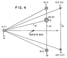
- Fig. 4 illustrates a nonsymmetrical mounting configuration in accordance with the invention.
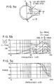
- Fig. 5a illustrates a mounting configuration with the center of mass of the HDA being located at a point other than the center of stiffness.
- Fig. 5b and fig. 5c illustrate transfer functions for the mode coupling for various distances between the center of mass of the HDA and the center of stiffness of the arrangement of Fig. 5a.
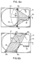
- Fig. 6a illustrates an existing mounting configuration for a typical rotary drive.
- Fig. 6b illustrates a mounting arrangement using isotropic vibration isolation mounts, wherein the drive of Fig. 6a is modified.
- Fig. 7a illustrates possible modes of vibration for a non-rigid user frame.
- Fig. 7b illustrates changes in the user frame to eliminate the modes of vibration illustrated in Fig. 7a.
- the method for producing an isolation system in accordance with the invention is described by reference to the parameters for a typical rotary drive.
- the HDA equations of motion are: where is the mass matrix, with m being the mass of the HDA and I zz being its moment of inertia calculated at the center of gravity about z-axis.
- the stiffness matrix is: The components in the stiffness matrix are given by: The damping matrix C is similar to equation 2 with all the "k” values replaced by "c".
- k x 1 , k x 2 , and k x 3 are the stiffness's of mounts 1, 2 and 3 in the x direction, respectively.
- the criteria to decouple the linear acceleration input and angular dynamics of the HDA is to simultaneously cause the four elements to be zero by choosing optimum location of the mounts or by choosing the mount parameters for a given location.
- the criteria for decoupling the mechanics is as follows: and For the rotary drive of the example, from the above equations, and assuming kxi's are equal to kyi's for isotropic mounts, the stiffness criterion is: or Thus the individual mount stiffnesses k x 1 , k x 2 , and k x 3 can be determined for optimal decoupling.
- Fig. 2 illustrates a typical geometry for a shock mount or isolator 40 which is isotropic for the x-y plane.
- a cylindrical geometry is used with the longitudinal axis of the cylinder being disposed in a direction which is perpendicular to the x-y plane.
- the drives have extending therefrom, extensions 70, to reach isolators 40 where necessary.
- the designer should choose an arrangement which maximizes the k 33 component. If it is difficult to change the shock mount parameters or their location to achieve the criteria in equation 4 set forth above, the center of mass of the HDA can be moved to match the closest possible stiffness/damping center. This may be done by adding a mass to the HDA.
- a nonsymmetrical configuration can be designed.
- Configuration 43 has equal mount parameters and the center of gravity is matched with the centeroid of the triangle ABC.
- Configuration 45 has two mounts at positions B1 and C1 with reduced parameters.
- Configuration 47 has one mount at position C2 with increased parameter. In all these cases the decoupling of rotational mode is achieved.
- Fig. 5a illustrates the case where the "center of stiffness/damping" of the mounting system is offset from the center of mass of the drive.
- Fig. 5b and Fig. 5c illustrate the effect on the rotational mode transfer function for three different offsets. It is observed that the extent of the coupling from the linear to rotational modes is gradually reduced as the design approaches the theoretical condition of the center of mass being at the center of stiffness and damping.
- Fig. 6a illustrates an existing structure for typical drive 80 in a user frame or enclosure 82.
- the center of mass is located at 84 and three isolators 86a, 86b and 86c are used.
- the isolators are shown in cross section, and are circular, with their longitudinal axes being in or parallel to the x-y plane.
- the housing for drive 80 has a so called clam shell cover having a boundary located along line 88.
- FIG. 6b an alternate mounting configuration is illustrated wherein rotational mode coupling is eliminated.
- the design assumes that the user frame 82 is rigid.
- Four isolators or vibration isolation mounts 90a, 90b, 90c and 90d of the type illustrated in Fig. 2 are used. Further, the geometries of the mount locations are altered so that the cylindrical axes of the mounts are perpendicular to the x-y plane so that the requirement for isotropy in that plane is satisfied. Finally, if necessary a mass 92 may be added to the drive 80 to move the center of mass of drive 80 to its optimum position as set forth above.
- Fig. 7a if the user frame or enclosure is not rigid, there are two potentially harmful modes of vibration.
- the "parallelogram mode” is assumed to be dominant.
- the "bow mode” can also be detrimental if the mounting locations are not properly chosen. Each case may give rise to substantial rotation of the HDA due to user frame flexibility.
- a modular design solution requires that the user frame be made as stiff as possible.
- Two approaches suggested in Fig. 7b are stiffer corners 100a and 100b which may be provided, for example, by increasing the thickness of the frame at those locations. Also suggested are areas of corrugation 102a and 102b which stiffen the frame to suppress the bow mode.
Landscapes
- Vibration Prevention Devices (AREA)
Applications Claiming Priority (2)
| Application Number | Priority Date | Filing Date | Title |
|---|---|---|---|
| US87871592A | 1992-04-30 | 1992-04-30 | |
| US878715 | 1992-04-30 |
Publications (2)
| Publication Number | Publication Date |
|---|---|
| EP0567833A2 true EP0567833A2 (en) | 1993-11-03 |
| EP0567833A3 EP0567833A3 (enExample) | 1994-01-05 |
Family
ID=25372662
Family Applications (1)
| Application Number | Title | Priority Date | Filing Date |
|---|---|---|---|
| EP93105942A Withdrawn EP0567833A2 (en) | 1992-04-30 | 1993-04-13 | Optimum rotational mode decoupling shock mount configuration for DASD's |
Country Status (3)
| Country | Link |
|---|---|
| EP (1) | EP0567833A2 (enExample) |
| JP (1) | JP2565637B2 (enExample) |
| CA (1) | CA2089792A1 (enExample) |
Cited By (9)
| Publication number | Priority date | Publication date | Assignee | Title |
|---|---|---|---|---|
| EP0715308A2 (en) | 1994-11-30 | 1996-06-05 | Hitachi, Ltd. | Supporting mechanism of disk unit in magnetic disk apparatus |
| EP0780845A1 (en) * | 1995-12-18 | 1997-06-25 | Hitachi, Ltd. | Rotary information recording and reproduction apparatus |
| US6125097A (en) * | 1998-11-05 | 2000-09-26 | Behavior Tech Computer Corp. | Shock absorbing device of CD-ROM reading mechanism |
| EP1063651A3 (en) * | 1999-06-21 | 2001-02-07 | Alps Electric Co., Ltd. | Magnetic disk drive in which a body including a chassis is rotatable with reference to a location displaced from the center of gravity of the body |
| WO2001031655A1 (en) * | 1999-10-28 | 2001-05-03 | Seagate Technology Llc | Process for designing an optimal vibration isolation mount for a disc drive |
| WO2001048758A1 (en) * | 1999-12-27 | 2001-07-05 | International Business Machines Corporation | Disk storage system and mounting system for head/disk assembly |
| WO2001091125A3 (en) * | 2000-05-22 | 2002-03-14 | Seagate Technology Llc | Disc-drive mounting using adhesive films |
| EP1035547A4 (en) * | 1998-09-29 | 2003-01-22 | Mitsubishi Electric Corp | CORNER PART REINFORCEMENT DEVICE FOR RACKING A PLATE DEVICE |
| US6999909B1 (en) | 1999-10-28 | 2006-02-14 | Seagate Technology Llc | Process for designing an optimal vibration isolation mount for a disc drive |
Families Citing this family (4)
| Publication number | Priority date | Publication date | Assignee | Title |
|---|---|---|---|---|
| US6583965B1 (en) * | 1999-04-21 | 2003-06-24 | Seagate Technology Llc | Inertia ring for improved rotational vibration performance |
| US6963463B2 (en) | 2002-05-24 | 2005-11-08 | Hitachi Global Storage Technologies Netherlands B.V. | Rotational vibration velocity-based sensor for disk drives |
| US6947243B2 (en) | 2002-05-24 | 2005-09-20 | Hitachi Global Storage Technologies Netherlands B.V. | Method and system for time-shift based rotational vibration sensing in disk drives |
| US6898046B2 (en) | 2002-05-24 | 2005-05-24 | Hitachi Global Storage Technologies Netherlands B.V. | Method and system for rotational velocity-based algorithm for vibration compensation in disk drives |
Family Cites Families (6)
| Publication number | Priority date | Publication date | Assignee | Title |
|---|---|---|---|---|
| GB665079A (en) * | 1949-02-21 | 1952-01-16 | Lord Mfg Co | Improvements in resilient mounting systems |
| GB2115203B (en) * | 1981-11-12 | 1985-10-30 | Logic Limited | A resilient mounting |
| US4683512A (en) * | 1985-07-08 | 1987-07-28 | Gold Star Co., Ltd. | Device for variably adjusting a moment of inertia of a drum of a videocassette recorder |
| JPS63203942A (ja) * | 1987-02-18 | 1988-08-23 | Seiko Epson Corp | 耐振構造 |
| JPH0632202B2 (ja) * | 1988-05-13 | 1994-04-27 | 富士通株式会社 | ディスク装置の防振構造 |
| DE8810371U1 (de) * | 1988-08-16 | 1989-09-14 | Siemens AG, 1000 Berlin und 8000 München | Elektronisches Gerät mit einem Laufwerkschalter zur Aufnahme eines Laufwerks für Disketten oder Festplatten |
-
1993
- 1993-02-18 CA CA 2089792 patent/CA2089792A1/en not_active Abandoned
- 1993-03-18 JP JP5058287A patent/JP2565637B2/ja not_active Expired - Lifetime
- 1993-04-13 EP EP93105942A patent/EP0567833A2/en not_active Withdrawn
Cited By (19)
| Publication number | Priority date | Publication date | Assignee | Title |
|---|---|---|---|---|
| EP0715308A2 (en) | 1994-11-30 | 1996-06-05 | Hitachi, Ltd. | Supporting mechanism of disk unit in magnetic disk apparatus |
| EP0715308A3 (en) * | 1994-11-30 | 1996-08-28 | Hitachi Ltd | Support mechanism for a disk drive in a magnetic disk assembly |
| US5740011A (en) * | 1994-11-30 | 1998-04-14 | Hitachi, Ltd. | Supporting mechanism of disk unit in magnetic disk apparatus having link mechanisms aligned with the center of gravity of the disk assembly |
| EP0780845A1 (en) * | 1995-12-18 | 1997-06-25 | Hitachi, Ltd. | Rotary information recording and reproduction apparatus |
| US5677813A (en) * | 1995-12-18 | 1997-10-14 | Hitachi, Ltd. | Rotary information recording and reproduction apparatus |
| EP1035547A4 (en) * | 1998-09-29 | 2003-01-22 | Mitsubishi Electric Corp | CORNER PART REINFORCEMENT DEVICE FOR RACKING A PLATE DEVICE |
| US6125097A (en) * | 1998-11-05 | 2000-09-26 | Behavior Tech Computer Corp. | Shock absorbing device of CD-ROM reading mechanism |
| KR100388117B1 (ko) * | 1999-06-21 | 2003-06-18 | 알프스 덴키 가부시키가이샤 | 자기디스크 구동장치 |
| US6456453B1 (en) | 1999-06-21 | 2002-09-24 | Alps Electric Co., Ltd. | Magnetic disk drive in which a body including a chassis is rotatable with reference to a location displaced from the center of gravity of the body |
| EP1063651A3 (en) * | 1999-06-21 | 2001-02-07 | Alps Electric Co., Ltd. | Magnetic disk drive in which a body including a chassis is rotatable with reference to a location displaced from the center of gravity of the body |
| GB2371917A (en) * | 1999-10-28 | 2002-08-07 | Seagate Technology Llc | Process for designing an optimal vibration isolation mount for a disc drive |
| WO2001031655A1 (en) * | 1999-10-28 | 2001-05-03 | Seagate Technology Llc | Process for designing an optimal vibration isolation mount for a disc drive |
| GB2371917B (en) * | 1999-10-28 | 2003-07-30 | Seagate Technology Llc | Process for designing an optimal vibration isolation mount for a disc drive |
| US6999909B1 (en) | 1999-10-28 | 2006-02-14 | Seagate Technology Llc | Process for designing an optimal vibration isolation mount for a disc drive |
| WO2001048758A1 (en) * | 1999-12-27 | 2001-07-05 | International Business Machines Corporation | Disk storage system and mounting system for head/disk assembly |
| WO2001091125A3 (en) * | 2000-05-22 | 2002-03-14 | Seagate Technology Llc | Disc-drive mounting using adhesive films |
| GB2378808A (en) * | 2000-05-22 | 2003-02-19 | Seagate Technology Llc | Disc-drive mounting using adhesive films |
| US6574099B2 (en) | 2000-05-22 | 2003-06-03 | Seagate Technology Llc | Disc-drive mounting using adhesive films |
| GB2378808B (en) * | 2000-05-22 | 2004-05-05 | Seagate Technology Llc | Disc-drive mounting using adhesive films |
Also Published As
| Publication number | Publication date |
|---|---|
| JP2565637B2 (ja) | 1996-12-18 |
| EP0567833A3 (enExample) | 1994-01-05 |
| CA2089792A1 (en) | 1993-10-31 |
| JPH0612852A (ja) | 1994-01-21 |
Similar Documents
| Publication | Publication Date | Title |
|---|---|---|
| KR100491402B1 (ko) | 디스크 저장 시스템 및 헤드/디스크 조립체용 장착 시스템 | |
| EP0567833A2 (en) | Optimum rotational mode decoupling shock mount configuration for DASD's | |
| EP0484433B1 (en) | Architecture for 2-1/2 inch diameter single disk drive | |
| US6275352B1 (en) | Individually tuned isolation devices for a disc drive base deck | |
| EP0556302B1 (en) | Multiple actuator disk drive | |
| US6029959A (en) | Semi-active vibration isolator and fine positioning mount | |
| JP2008213141A (ja) | 力学的に平衡の超小型可動子 | |
| WO1993023783A1 (en) | Dual image head-mounted display | |
| US6339511B1 (en) | Lens actuator and optical disk recording and reading apparatus using the same | |
| JPH0393087A (ja) | 磁気ディスク装置 | |
| JP2005302246A (ja) | 磁気ディスク装置 | |
| US4943147A (en) | Chopping secondary mirror system | |
| JPH05159262A (ja) | ディスク記憶装置のヘッド支持機構 | |
| JPH1011957A (ja) | 記録再生装置 | |
| JP2538036B2 (ja) | 磁気ディスク装置の筐体及びその防振方法 | |
| JP2754413B2 (ja) | 磁気ディスク装置 | |
| CN109368032A (zh) | 一种新型多重防震仪表箱装置 | |
| JP2855907B2 (ja) | 防振用多軸ダンパおよび記録再生装置 | |
| JP2777917B2 (ja) | 磁気ディスク装置 | |
| CN118565467A (zh) | 一种混合式激光惯导两级隔振系统 | |
| JPH10205565A (ja) | ダンパー、防振装置及びディスク装置 | |
| JPH09147540A (ja) | 情報磁気記憶装置用ベース | |
| HK1051736A (en) | Disk storage system and mounting system for head/disk assembly | |
| JPS6286590A (ja) | ヘツド支持機構 | |
| JPH05325496A (ja) | ディスク装置 |
Legal Events
| Date | Code | Title | Description |
|---|---|---|---|
| PUAI | Public reference made under article 153(3) epc to a published international application that has entered the european phase |
Free format text: ORIGINAL CODE: 0009012 |
|
| AK | Designated contracting states |
Kind code of ref document: A2 Designated state(s): AT BE CH DE ES FR GB IT LI NL SE |
|
| PUAL | Search report despatched |
Free format text: ORIGINAL CODE: 0009013 |
|
| AK | Designated contracting states |
Kind code of ref document: A3 Designated state(s): AT BE CH DE ES FR GB IT LI NL SE |
|
| 17P | Request for examination filed |
Effective date: 19931227 |
|
| 17Q | First examination report despatched |
Effective date: 19961105 |
|
| 18D | Application deemed to be withdrawn |
Effective date: 19970318 |