EP0566265A2 - Rechnerhinweisanordnung mit Reinigungsalarm - Google Patents
Rechnerhinweisanordnung mit Reinigungsalarm Download PDFInfo
- Publication number
- EP0566265A2 EP0566265A2 EP93302338A EP93302338A EP0566265A2 EP 0566265 A2 EP0566265 A2 EP 0566265A2 EP 93302338 A EP93302338 A EP 93302338A EP 93302338 A EP93302338 A EP 93302338A EP 0566265 A2 EP0566265 A2 EP 0566265A2
- Authority
- EP
- European Patent Office
- Prior art keywords
- cleaning
- pointing device
- alarm signal
- movable portions
- determination means
- Prior art date
- Legal status (The legal status is an assumption and is not a legal conclusion. Google has not performed a legal analysis and makes no representation as to the accuracy of the status listed.)
- Withdrawn
Links
Images


Classifications
-
- G—PHYSICS
- G06—COMPUTING OR CALCULATING; COUNTING
- G06F—ELECTRIC DIGITAL DATA PROCESSING
- G06F3/00—Input arrangements for transferring data to be processed into a form capable of being handled by the computer; Output arrangements for transferring data from processing unit to output unit, e.g. interface arrangements
- G06F3/01—Input arrangements or combined input and output arrangements for interaction between user and computer
- G06F3/03—Arrangements for converting the position or the displacement of a member into a coded form
- G06F3/033—Pointing devices displaced or positioned by the user, e.g. mice, trackballs, pens or joysticks; Accessories therefor
- G06F3/038—Control and interface arrangements therefor, e.g. drivers or device-embedded control circuitry
-
- G—PHYSICS
- G06—COMPUTING OR CALCULATING; COUNTING
- G06F—ELECTRIC DIGITAL DATA PROCESSING
- G06F3/00—Input arrangements for transferring data to be processed into a form capable of being handled by the computer; Output arrangements for transferring data from processing unit to output unit, e.g. interface arrangements
- G06F3/01—Input arrangements or combined input and output arrangements for interaction between user and computer
- G06F3/03—Arrangements for converting the position or the displacement of a member into a coded form
- G06F3/0304—Detection arrangements using opto-electronic means
- G06F3/0312—Detection arrangements using opto-electronic means for tracking the rotation of a spherical or circular member, e.g. optical rotary encoders used in mice or trackballs using a tracking ball or in mouse scroll wheels
-
- G—PHYSICS
- G06—COMPUTING OR CALCULATING; COUNTING
- G06F—ELECTRIC DIGITAL DATA PROCESSING
- G06F3/00—Input arrangements for transferring data to be processed into a form capable of being handled by the computer; Output arrangements for transferring data from processing unit to output unit, e.g. interface arrangements
- G06F3/01—Input arrangements or combined input and output arrangements for interaction between user and computer
- G06F3/03—Arrangements for converting the position or the displacement of a member into a coded form
- G06F3/033—Pointing devices displaced or positioned by the user, e.g. mice, trackballs, pens or joysticks; Accessories therefor
- G06F3/0354—Pointing devices displaced or positioned by the user, e.g. mice, trackballs, pens or joysticks; Accessories therefor with detection of two-dimensional [2D] relative movements between the device, or an operating part thereof, and a plane or surface, e.g. 2D mice, trackballs, pens or pucks
- G06F3/03543—Mice or pucks
Definitions
- the present invention relates to a pointing device for use with a personal computer, etc., and more particularly to a pointing device with a cleaning alarm, which warns the user when cleaning becomes necessary due to excessive contamination.
- a mouse is an example of a typical pointing device used on a personal computer or a work station.
- mice There are two types of mice, namely optical mice and mechanical mice, the latter being widely used at present.
- a mechanical mouse is slid on a desk surface to rotate a ball on its underside, the ball's rotation being conveyed to two rollers. Rotation of each roller is detected by an encoder to calculate the amount of movement of the mouse. On a display screen, a pointer moves according to the result of this calculation.
- the use of such a mechanical mouse over a long period of time causes dust or dirt to adhere to the surfaces of the ball and rollers, which may prevent the pointer from precisely following the mouse's movement, and in due course may cause a failure of the mouse.
- Japanese Published Unexamined Patent Application (PUPA) No.62-135927 discloses a pointing device having cleaning members for removing dust that contacts and adheres to the ball and encoder rollers, respectively. Both cleaning members are made of materials which do not hinder the smooth rotation of the ball and rollers, and remove dust or dirt adhered to the surfaces of the ball and rollers as they rotate.
- Japanese PUPA No.1-94422 discloses a pointing device in which a member for cleaning the surface of a ball is detachably mounted at a ball supporting section
- Japanese Published Examined Utility Model Application No.2-77741 discloses a mouse provided with a brush which contacts a driver rotating according to the rotation of a ball.
- an object of the present invention is to provide means for automatically notifying the user that the cleaning of a pointing device such as a mouse is necessary.
- Another object of the present invention is to encourage the prevention of contamination trouble by cleaning, and so improve the lifetime of a pointing device.
- the present invention provides a pointing device including movable portions which periodically require cleaning, the device generating move signals for controlling a pointer on a display screen based on the quantity of motion of said movable portions, said pointing device being characterised by: cleaning time determination means for determining when cleaning of said movable portions becomes necessary; and indicator means for providing visual indication when said determination means has determined that cleaning is necessary.
- the present invention provides a computer system having a pointing device including movable portions requiring cleaning, a system unit to which said pointing device is connected, and a display device for displaying a pointer on a screen, the pointing device generating move signals for controlling the pointer based on the quantity of motion of said movable portions, said computer system being characterised in that: said pointing device is provided with cleaning time determination means for determining when cleaning of said movable portions becomes necessary; and visual indication is provided on the screen of said display device to prompt cleaning when said determination means has determined that cleaning is necessary.
- the pointing device has detection means for detecting the quantity of motion of the movable portions, for example a plurality of encoders which produce pulses as the movable portions move; these pulses are then used to calculate the move signals.
- the cleaning time determination means includes an accumulator for accumulating the quantity of motion detected by the detection means and a generation means for generating an alarm signal when the result of the accumulation reaches a predetermined threshold, the indicator means providing visual indication in response to the alarm signal.
- the cleaning time determination means may comprise: counting means for separately counting the pulses produced by each encoder and producing an output signal if the count from any particular encoder exceeds a predetermined value; a generation means responsive to the output signal of the counting means to produce an alarm signal, said alarm signal causing the indicator means to provide the visual indication; the pulse count for each encoder being reset when any of other encoders produces a pulse.
- the pointing device may comprise movable portions consisting of at least three rollers contacting a main movable portion.
- a suitable cleaning time determination means could comprise: measuring means to measure the angular velocity of each roller; calculation means to calculate the theoretical angular velocity of a particular roller from the measured angular velocity of the other rollers; and threshold means to determine the difference between the theoretical angular velocity of the particular roller and the actual angular velocity of the particular roller measured by the measuring means, and to produce an alarm signal if the difference exceeds a threshold value; said alarm signal causing the indicator means to provide the visual indication.
- Another arrangement for the cleaning time determination means which can be employed comprises: a light source for directing light onto the movable portions; a detector for sensing reflected light from the movable portions; and generating means for generating an alarm signal if the amount of reflected light is less than a threshold value, the alarm signal causing the indicator means to provide the visual indication.
- reset means for resetting the cleaning time determination means will typically be provided.
- reset means will be activated by a user-operated switch located on the pointing device and only accessible by disassembling the pointing device.
- a cleaning time is determined when the accumulated value of quantities of motion of the pointing device or a pointer reaches a predetermined value, when the analysis of output data from plural encoders shows a tendency of contamination, or when contamination is detected by direct monitoring of the movable portions with a photo sensor or the like.
- the indicator which provides visual indication based on the alarm signal from the cleaning time determination means, may be a light-emitting diode (LED) or a liquid crystal display (LCD).
- a mouse is taken as an example of a pointing device, but the present invention is not limited to a mouse and can be applied to any pointing device including rotatable or movable portions that need to be cleaned.
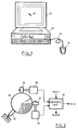
- the mouse of the preferred embodiment can be connected to a personal computer system (for example, PS/2 Model 30) as shown in FIG.1.
- a mouse 10 is connected to a predetermined port at the rear side of a system unit 12 through a cable 14.
- a pointer or cursor 18 moves on the screen of a display device 16 in response thereto.
- a keyboard is also connected to the system unit 12. Since the configuration and operations of such a system are well known in the art and are not directly related to the present invention, further details thereof will not be described herein.
- the overall configuration of the mouse 10 is schematically shown in FIG.2.
- the mouse 10 comprises a ball 20 rotated by sliding on a flat surface of a desk or the like, two rollers 22 and 24 for conveying the rotation of the ball 20 in X and Y directions respectively, two rotary encoders 26 and 28 for detecting the quantities of rotation of the respective rollers, and an arithmetic unit 30 for calculating the quantity of movement of the mouse 10 based on pulse outputs from the encoders.
- a push wheel 32 presses the ball 20 toward the rollers 22 and 24 by means of a spring force.
- the mouse of the preferred embodiment includes cleaning time determination means for automatically determining when cleaning is necessary and generating an alarm signal.
- FIG.2 shows an embodiment wherein the cleaning time determination means is provided in the arithmetic unit 30.
- the cleaning time determination means can be provided independently of the arithmetic unit 30.
- a reset signal to the arithmetic unit 30 is generated by depressing a reset switch described later to reset the cleaning time determination means.
- X counter 40 counts pulses from the encoder 26, while Y counter 42 counts pulses from the encoder 28.
- the counters 40 and 42 are to be cleared simultaneously at a constant time interval (for example, every 10 milliseconds) and provide the maximum X and Y count values to a sender 44 before they are cleared. These count values indicate the quantities of movement or running distances of the mouse 10 in the X and Y directions.
- the sender 44 creates a send format for the system unit 12 based on the counter values from the counters 40 and 42, and then serializes and sends it to the system unit 12 at the time interval of, for example, 10 milliseconds.
- the system unit 12 calculates the quantity of movement of the pointer 18, based on the counter values, and accordingly moves the pointer 18 on the screen.
- the X and Y count values from the X and Y counters 40 and 42 are also provided to an accumulator 46.
- This accumulator 46 as well as a threshold register 48, a comparator 50, and an indicator 52 are components provided for the purposes of the preferred embodiment of the present invention.
- the accumulator 46 accumulates both count values to calculate an accumulated running distance of the mouse 10 and may be comprised of two adders and a nonvolatile memory such as an EEPROM.
- FIG.4 shows an example of the configuration of the accumulator. In FIG.4, a first adder 60 adds X and Y count values and a second adder 62 adds a sum value from the adder 60 and an accumulated value stored in a nonvolatile memory 64.
- the output of the adder 62 is written into the nonvolatile memory 64 as a new accumulated value.
- An accumulated value read from the nonvolatile memory 64 is provided not only to one input of the adder 62, but also to the comparator 50.
- the sum of X and Y count values is accumulated as a value corresponding to the running distance of the mouse 10, but instead the count values may be accumulated separately.
- a square root of the sum of squared count values may be accumulated, but this calculation is troublesome.
- the threshold register 48 is a nonvolatile memory in which a predetermined threshold value is stored. From a hardware point of view, a part of the nonvolatile memory 64 shown in FIG.4 can be used as a threshold register.
- a cleaning alarm is issued when the sum of an accumulated running distance in the X direction and an accumulated running distance in the Y direction (greater than the actual running distance) reaches 10km.
- a value (pulse count value) corresponding to 10km is previously stored in the threshold register.
- a value corresponding to 1 x 10⁸ is stored in the threshold register 48. Needless to say, this value may be varied depending on the mouse used and the configuration of the accumulator 46.
- the comparator 50 compares the accumulated value from the accumulator 46 with the threshold value from the threshold register 48, and generates an alarm signal if they coincide with each other.
- the alarm signal is applied to the indicator 52 such as an LED wherein visual indication is provided by turning it on.
- the indicator 52 is provided at a conspicuous location on the mouse 10.
- the preferred embodiment of the present invention issues a cleaning alarm by means of a visual indication to prompt the user to clean the mouse. Since the accumulated value must be reset to zero after cleaning, a reset switch is provided on the mouse 10. When the user depresses the reset switch after cleaning, the accumulated value stored in the nonvolatile memory 64 of the accumulator 46 is cleared, that is, zeros are written into the memory 64.
- a clear circuit 66 shown in FIG.4 is activated by a reset signal generated by the depression of the reset switch to write zeros into the nonvolatile memory 64.
- the two inputs to the comparator 50 no longer coincide with each other so that the alarm signal is turned off and the visual indication from the indicator 52 disappears.
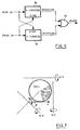
- FIG.5 An example of a suitable reset switch is shown in FIG.5.
- a cap 70 with a circular opening in its center is removed from the ball 20 (as indicated by a dotted line with an arrow) for cleaning, a reset switch 72 will appear.
- the user cannot touch the reset switch 72 while using the mouse since it is covered with the cap 70. Therefore, in the situation where a cleaning alarm is issued by turning the indicator 52 on, it cannot be turned off unless the cap 70 is removed, which enforces cleaning upon the user.
- a cleaning alarm is issued based on a running distance of the mouse, but instead (or additionally) the alarm may be issued by directly analyzing the outputs of the rotary encoders 26 and 28.
- the alarm may be issued by directly analyzing the outputs of the rotary encoders 26 and 28.
- the alarm may be issued by directly analyzing the outputs of the rotary encoders 26 and 28.
- An example implementing this feature is shown in FIG.6.
- Counters 80 and 82 count pulses from the encoders 26 and 28, respectively, and generate an overflow signal when the count value reaches 200.
- Each overflow signal is provided to an OR gate 84, the output of which is an alarm signal.
- Each counter is cleared by a pulse from the encoder associated with the other counter. That is, the X counter 80 is cleared by a pulse from the encoder 28, while the Y counter 82 is cleared by a pulse from the encoder 26.
- the numerical value 200 in this embodiment is for design purpose and may be changed as required.
- a cleaning alarm may be issued based on a slip between the ball and the rollers.
- a difference between the theoretical value and the actually measured value ⁇ a is calculated as a slip ⁇ a and a cleaning alarm is issued when it reaches a predetermined value.
- Contamination can be directly detected by applying light onto the surface of the ball or the rollers and sensing reflected light by a photosensor. Since the amount of reflected light would decrease if the surface becomes darkish due to dust or dirt adhered thereto, a cleaning alarm may be issued when it reaches a predetermined value.
- the various cleaning time determination means heretofore described and other possible cleaning time determination means may be combined to notify a cleaning time by ORing their outputs.
- the display device 16 of the computer system may be used instead of providing an LED or the like on the mouse.
- an alarm signal from the comparator 50 shown in FIG.3 or the OR gate 84 shown in FIG.6 is sent, through the cable 14, to the system unit 12.
- There are two methods for displaying a cleaning message (for example, "Mouse should be cleaned.") on the screen of the display device 16.
- the first method displays the message when an alarm signal is detected at the time of diagnostic test after power on. This can be done without the intervention of an operating system (OS).
- the second method displays the message in real time when an alarm signal is detected during normal operations. In this method, it is necessary to add a cleaning message display function to a mouse driver of the OS.
- a diagnostic program or a mouse driver can be easily modified.
- a user is automatically notified by way of visual indication that the time has come when movable portions such as ball and rollers need to be cleaned, which has the effect of promoting cleaning at the appropriate time.
Landscapes
- Engineering & Computer Science (AREA)
- General Engineering & Computer Science (AREA)
- Theoretical Computer Science (AREA)
- Human Computer Interaction (AREA)
- Physics & Mathematics (AREA)
- General Physics & Mathematics (AREA)
- Position Input By Displaying (AREA)
Applications Claiming Priority (2)
| Application Number | Priority Date | Filing Date | Title |
|---|---|---|---|
| JP4091365A JPH05298021A (ja) | 1992-04-13 | 1992-04-13 | クリーニング・アラーム付ポインティング・デバイス |
| JP91365/92 | 1992-04-13 |
Publications (2)
| Publication Number | Publication Date |
|---|---|
| EP0566265A2 true EP0566265A2 (de) | 1993-10-20 |
| EP0566265A3 EP0566265A3 (en) | 1995-10-11 |
Family
ID=14024360
Family Applications (1)
| Application Number | Title | Priority Date | Filing Date |
|---|---|---|---|
| EP93302338A Withdrawn EP0566265A3 (en) | 1992-04-13 | 1993-03-26 | Computer pointing device with cleaning alarm |
Country Status (4)
| Country | Link |
|---|---|
| US (1) | US5436616A (de) |
| EP (1) | EP0566265A3 (de) |
| JP (1) | JPH05298021A (de) |
| BR (1) | BR9301332A (de) |
Cited By (4)
| Publication number | Priority date | Publication date | Assignee | Title |
|---|---|---|---|---|
| EP1122683A3 (de) * | 2000-02-02 | 2001-09-26 | Etostem Co., Ltd. | Maus für persönliche Rechner |
| GB2424971A (en) * | 2005-04-06 | 2006-10-11 | David Miller | Scheduled cleaning and auditing of computer keyboards |
| WO2006111196A1 (en) * | 2005-04-22 | 2006-10-26 | 3Dconnexion Holding S.A. | Manual input device memory |
| EP2620841A1 (de) * | 2005-02-17 | 2013-07-31 | Advanced Input Devices, Inc. | Keyboard-Baugruppe |
Families Citing this family (12)
| Publication number | Priority date | Publication date | Assignee | Title |
|---|---|---|---|---|
| JPH07191805A (ja) * | 1993-12-27 | 1995-07-28 | Rohm Co Ltd | ロータリエンコーダおよびこれを用いた入力装置 |
| JPH08152964A (ja) * | 1994-11-28 | 1996-06-11 | Nec Gumma Ltd | マウス |
| US5606563A (en) * | 1995-05-18 | 1997-02-25 | Pmc-Sierra, Inc. | Programmable jump window for sonet compliant bit error monitoring |
| US5850661A (en) * | 1996-11-25 | 1998-12-22 | Lawrence; Arthur V. | Device for cleaning computer mouse ball |
| US6046729A (en) * | 1998-03-24 | 2000-04-04 | Primax Electronics Ltd. | Z axis device of a computer mouse |
| US6285353B1 (en) | 1998-06-18 | 2001-09-04 | Micron Technology, Inc. | Self cleaning computer pointer or mouse |
| US6469693B1 (en) * | 2000-01-11 | 2002-10-22 | Logitech Europe S.A. | Computer mouse with single-piece top and single-piece bottom |
| TW523140U (en) * | 2000-09-29 | 2003-03-01 | Meng-Yu Wei | Improved mouse structure |
| CN100430876C (zh) * | 2004-02-06 | 2008-11-05 | 原相科技股份有限公司 | 指针装置及轨迹平滑方法 |
| WO2005119356A2 (en) | 2004-05-28 | 2005-12-15 | Erik Jan Banning | Interactive direct-pointing system and calibration method |
| US9285897B2 (en) | 2005-07-13 | 2016-03-15 | Ultimate Pointer, L.L.C. | Easily deployable interactive direct-pointing system and calibration method therefor |
| WO2019074440A1 (en) | 2017-10-10 | 2019-04-18 | Razer (Asia-Pacific) Pte. Ltd. | METHOD AND APPARATUS FOR MOVING PERFORMANCE ANALYSIS OF MOUSE |
Family Cites Families (4)
| Publication number | Priority date | Publication date | Assignee | Title |
|---|---|---|---|---|
| US4501005A (en) * | 1982-05-21 | 1985-02-19 | Atlas Electronics International, Inc. | Vehicle elapsed mileage indicator |
| US4815014A (en) * | 1987-02-27 | 1989-03-21 | Westinghouse Electric Corp. | Machine assisted execution of process operating procedures |
| JPH0435953Y2 (de) * | 1987-04-28 | 1992-08-25 | ||
| JP3066122B2 (ja) * | 1991-07-12 | 2000-07-17 | アルプス電気株式会社 | X−y座標入力装置 |
-
1992
- 1992-04-13 JP JP4091365A patent/JPH05298021A/ja active Pending
-
1993
- 1993-03-26 EP EP93302338A patent/EP0566265A3/en not_active Withdrawn
- 1993-03-26 BR BR9301332A patent/BR9301332A/pt active Search and Examination
- 1993-04-13 US US08/046,528 patent/US5436616A/en not_active Expired - Fee Related
Cited By (4)
| Publication number | Priority date | Publication date | Assignee | Title |
|---|---|---|---|---|
| EP1122683A3 (de) * | 2000-02-02 | 2001-09-26 | Etostem Co., Ltd. | Maus für persönliche Rechner |
| EP2620841A1 (de) * | 2005-02-17 | 2013-07-31 | Advanced Input Devices, Inc. | Keyboard-Baugruppe |
| GB2424971A (en) * | 2005-04-06 | 2006-10-11 | David Miller | Scheduled cleaning and auditing of computer keyboards |
| WO2006111196A1 (en) * | 2005-04-22 | 2006-10-26 | 3Dconnexion Holding S.A. | Manual input device memory |
Also Published As
| Publication number | Publication date |
|---|---|
| JPH05298021A (ja) | 1993-11-12 |
| BR9301332A (pt) | 1993-10-19 |
| EP0566265A3 (en) | 1995-10-11 |
| US5436616A (en) | 1995-07-25 |
Similar Documents
| Publication | Publication Date | Title |
|---|---|---|
| EP0566265A2 (de) | Rechnerhinweisanordnung mit Reinigungsalarm | |
| US6225617B1 (en) | Method for generating quasi-sinusoidal signals | |
| US10161886B2 (en) | Detection of surface contamination | |
| US5789739A (en) | Optical detection device for determining the position of an indicator medium | |
| JP2907216B2 (ja) | 航空機に用いられる多機能メータ | |
| EP0829799A3 (de) | Wandcomputereinheit | |
| EP1182606A2 (de) | Vierachsige optische Maus | |
| EP0417141A1 (de) | Digitales mess- und proportionierungsinstrument | |
| WO1998040705A2 (en) | A system and method for accurately weighing and characterizing moving vehicles | |
| CA2283045A1 (en) | A method and system for environmental sensing and control within a computer system | |
| FR2869981A1 (fr) | Roulement capteur de deformations comprenant quatre jauges de contraintes | |
| EP2015020B1 (de) | Vorrichtung und Verfahren zur Texturmessung | |
| US7847704B2 (en) | Method and device for transmitting signals from a position measuring arrangement to an evaluation unit | |
| CN111037609A (zh) | 一种轮式机器人打滑卡阻检测系统及方法 | |
| EP1478944B1 (de) | Ultraschall-geschwindigkeits-messfühler und dazu zugehöriger korrelations-algorithmus | |
| JPH0750424B2 (ja) | タッチパネルの制御方法およびタッチパネル装置 | |
| JP3324835B2 (ja) | 光学的検出装置 | |
| JP2752804B2 (ja) | 変位測定装置 | |
| SU1539810A1 (ru) | Устройство дл определени параметров технического обслуживани издели | |
| JPS5648363A (en) | Irregular sheet monitor system | |
| GB2236858A (en) | Dual encoder for electronic tape measure | |
| JPH045718A (ja) | 入力装置 | |
| TW259697B (en) | Method and apparatus for sensing pollution level of dustcloth of wet cleaner | |
| JP2005346230A (ja) | 光学式座標入力装置 | |
| Kishizada | Development Of Ultrasonic Measuring Devices (Sensors) That Determine The Level Of Liquid In Tanks |
Legal Events
| Date | Code | Title | Description |
|---|---|---|---|
| PUAI | Public reference made under article 153(3) epc to a published international application that has entered the european phase |
Free format text: ORIGINAL CODE: 0009012 |
|
| AK | Designated contracting states |
Kind code of ref document: A2 Designated state(s): DE FR GB |
|
| 17P | Request for examination filed |
Effective date: 19931227 |
|
| PUAL | Search report despatched |
Free format text: ORIGINAL CODE: 0009013 |
|
| AK | Designated contracting states |
Kind code of ref document: A3 Designated state(s): DE FR GB |
|
| STAA | Information on the status of an ep patent application or granted ep patent |
Free format text: STATUS: THE APPLICATION HAS BEEN WITHDRAWN |
|
| 18W | Application withdrawn |
Withdrawal date: 19980512 |