EP0565921A2 - Rain water treating and conveying installation for use as industrial water or for treatment for the purpose of infiltration or inflow in receiving water - Google Patents
Rain water treating and conveying installation for use as industrial water or for treatment for the purpose of infiltration or inflow in receiving water Download PDFInfo
- Publication number
- EP0565921A2 EP0565921A2 EP19930104881 EP93104881A EP0565921A2 EP 0565921 A2 EP0565921 A2 EP 0565921A2 EP 19930104881 EP19930104881 EP 19930104881 EP 93104881 A EP93104881 A EP 93104881A EP 0565921 A2 EP0565921 A2 EP 0565921A2
- Authority
- EP
- European Patent Office
- Prior art keywords
- filter
- water
- plant according
- rainwater
- overflow
- Prior art date
- Legal status (The legal status is an assumption and is not a legal conclusion. Google has not performed a legal analysis and makes no representation as to the accuracy of the status listed.)
- Withdrawn
Links
- XLYOFNOQVPJJNP-UHFFFAOYSA-N water Substances O XLYOFNOQVPJJNP-UHFFFAOYSA-N 0.000 title claims abstract description 123
- 238000009434 installation Methods 0.000 title claims abstract description 16
- 238000001764 infiltration Methods 0.000 title claims description 8
- 230000008595 infiltration Effects 0.000 title claims description 8
- 239000008235 industrial water Substances 0.000 title description 2
- 238000003860 storage Methods 0.000 claims abstract description 75
- 238000004062 sedimentation Methods 0.000 claims abstract description 18
- 230000001419 dependent effect Effects 0.000 claims abstract 2
- 239000000126 substance Substances 0.000 claims description 16
- 239000003651 drinking water Substances 0.000 claims description 15
- 235000020188 drinking water Nutrition 0.000 claims description 15
- 238000004140 cleaning Methods 0.000 claims description 14
- 238000004519 manufacturing process Methods 0.000 claims description 11
- 239000013049 sediment Substances 0.000 claims description 11
- 238000011001 backwashing Methods 0.000 claims description 9
- 229920003023 plastic Polymers 0.000 claims description 8
- 239000004033 plastic Substances 0.000 claims description 8
- 238000000034 method Methods 0.000 claims description 6
- 230000008569 process Effects 0.000 claims description 6
- 239000004927 clay Substances 0.000 claims description 5
- 230000008014 freezing Effects 0.000 claims description 5
- 238000007710 freezing Methods 0.000 claims description 5
- 238000007789 sealing Methods 0.000 claims description 5
- 239000003795 chemical substances by application Substances 0.000 claims description 4
- 238000007667 floating Methods 0.000 claims description 4
- 238000011010 flushing procedure Methods 0.000 claims description 4
- 244000005700 microbiome Species 0.000 claims description 4
- 239000008187 granular material Substances 0.000 claims description 3
- 239000000463 material Substances 0.000 claims description 3
- 239000002245 particle Substances 0.000 claims description 3
- 239000004575 stone Substances 0.000 claims description 3
- 241000244206 Nematoda Species 0.000 claims description 2
- CBENFWSGALASAD-UHFFFAOYSA-N Ozone Chemical compound [O-][O+]=O CBENFWSGALASAD-UHFFFAOYSA-N 0.000 claims description 2
- -1 bark Substances 0.000 claims description 2
- 239000011449 brick Substances 0.000 claims description 2
- 239000003610 charcoal Substances 0.000 claims description 2
- 230000003111 delayed effect Effects 0.000 claims description 2
- 239000008262 pumice Substances 0.000 claims description 2
- 239000002893 slag Substances 0.000 claims description 2
- 101100058224 Arabidopsis thaliana BEH1 gene Proteins 0.000 claims 4
- 101100058225 Arabidopsis thaliana BEH2 gene Proteins 0.000 claims 3
- OKTJSMMVPCPJKN-UHFFFAOYSA-N Carbon Chemical compound [C] OKTJSMMVPCPJKN-UHFFFAOYSA-N 0.000 claims 2
- 238000004026 adhesive bonding Methods 0.000 claims 1
- 238000001914 filtration Methods 0.000 abstract description 20
- 238000010276 construction Methods 0.000 abstract description 10
- 238000012423 maintenance Methods 0.000 abstract description 5
- 238000011049 filling Methods 0.000 abstract description 3
- 238000005325 percolation Methods 0.000 abstract 3
- 238000012856 packing Methods 0.000 abstract 1
- 238000000746 purification Methods 0.000 abstract 1
- 238000005406 washing Methods 0.000 description 10
- 238000013461 design Methods 0.000 description 9
- 239000002689 soil Substances 0.000 description 8
- 239000003344 environmental pollutant Substances 0.000 description 7
- 231100000719 pollutant Toxicity 0.000 description 7
- 238000011109 contamination Methods 0.000 description 6
- 239000000356 contaminant Substances 0.000 description 5
- 230000000717 retained effect Effects 0.000 description 4
- 239000010802 sludge Substances 0.000 description 4
- 238000009825 accumulation Methods 0.000 description 3
- 238000002474 experimental method Methods 0.000 description 3
- 239000000203 mixture Substances 0.000 description 3
- 235000015097 nutrients Nutrition 0.000 description 3
- 239000011148 porous material Substances 0.000 description 3
- 238000001556 precipitation Methods 0.000 description 3
- 238000005070 sampling Methods 0.000 description 3
- 239000010865 sewage Substances 0.000 description 3
- 239000002351 wastewater Substances 0.000 description 3
- 238000004065 wastewater treatment Methods 0.000 description 3
- 241000196324 Embryophyta Species 0.000 description 2
- 241001465754 Metazoa Species 0.000 description 2
- 239000003599 detergent Substances 0.000 description 2
- 238000011161 development Methods 0.000 description 2
- 230000018109 developmental process Effects 0.000 description 2
- 238000009826 distribution Methods 0.000 description 2
- 238000005516 engineering process Methods 0.000 description 2
- 239000003673 groundwater Substances 0.000 description 2
- 238000003306 harvesting Methods 0.000 description 2
- 230000014759 maintenance of location Effects 0.000 description 2
- 239000012528 membrane Substances 0.000 description 2
- 238000002156 mixing Methods 0.000 description 2
- 239000004576 sand Substances 0.000 description 2
- 238000000926 separation method Methods 0.000 description 2
- 238000004659 sterilization and disinfection Methods 0.000 description 2
- 238000013517 stratification Methods 0.000 description 2
- 239000002023 wood Substances 0.000 description 2
- OYPRJOBELJOOCE-UHFFFAOYSA-N Calcium Chemical compound [Ca] OYPRJOBELJOOCE-UHFFFAOYSA-N 0.000 description 1
- 241001507939 Cormus domestica Species 0.000 description 1
- 241001295925 Gegenes Species 0.000 description 1
- PEDCQBHIVMGVHV-UHFFFAOYSA-N Glycerine Chemical compound OCC(O)CO PEDCQBHIVMGVHV-UHFFFAOYSA-N 0.000 description 1
- FYYHWMGAXLPEAU-UHFFFAOYSA-N Magnesium Chemical compound [Mg] FYYHWMGAXLPEAU-UHFFFAOYSA-N 0.000 description 1
- 229920000426 Microplastic Polymers 0.000 description 1
- 229910019142 PO4 Inorganic materials 0.000 description 1
- 206010000496 acne Diseases 0.000 description 1
- 239000008186 active pharmaceutical agent Substances 0.000 description 1
- 230000006978 adaptation Effects 0.000 description 1
- 230000004888 barrier function Effects 0.000 description 1
- 230000009286 beneficial effect Effects 0.000 description 1
- 230000008901 benefit Effects 0.000 description 1
- 230000003115 biocidal effect Effects 0.000 description 1
- 230000033228 biological regulation Effects 0.000 description 1
- 238000009395 breeding Methods 0.000 description 1
- 230000001488 breeding effect Effects 0.000 description 1
- 239000011575 calcium Substances 0.000 description 1
- 229910052791 calcium Inorganic materials 0.000 description 1
- 230000001914 calming effect Effects 0.000 description 1
- 230000015556 catabolic process Effects 0.000 description 1
- 150000001768 cations Chemical class 0.000 description 1
- 238000009833 condensation Methods 0.000 description 1
- 230000005494 condensation Effects 0.000 description 1
- 230000001276 controlling effect Effects 0.000 description 1
- 238000006731 degradation reaction Methods 0.000 description 1
- 230000029087 digestion Effects 0.000 description 1
- 239000003657 drainage water Substances 0.000 description 1
- 238000000469 dry deposition Methods 0.000 description 1
- 230000000694 effects Effects 0.000 description 1
- 235000013601 eggs Nutrition 0.000 description 1
- 230000008030 elimination Effects 0.000 description 1
- 238000003379 elimination reaction Methods 0.000 description 1
- 238000000605 extraction Methods 0.000 description 1
- 239000004744 fabric Substances 0.000 description 1
- 230000002349 favourable effect Effects 0.000 description 1
- 210000003608 fece Anatomy 0.000 description 1
- 239000010419 fine particle Substances 0.000 description 1
- 238000009472 formulation Methods 0.000 description 1
- 239000000446 fuel Substances 0.000 description 1
- 230000006870 function Effects 0.000 description 1
- 210000004907 gland Anatomy 0.000 description 1
- 238000010438 heat treatment Methods 0.000 description 1
- 238000011086 high cleaning Methods 0.000 description 1
- 239000003864 humus Substances 0.000 description 1
- 230000002706 hydrostatic effect Effects 0.000 description 1
- 238000007654 immersion Methods 0.000 description 1
- 239000004615 ingredient Substances 0.000 description 1
- 230000001788 irregular Effects 0.000 description 1
- 238000011068 loading method Methods 0.000 description 1
- 239000011777 magnesium Substances 0.000 description 1
- 229910052749 magnesium Inorganic materials 0.000 description 1
- 238000005259 measurement Methods 0.000 description 1
- 239000002557 mineral fiber Substances 0.000 description 1
- 210000002445 nipple Anatomy 0.000 description 1
- 230000000149 penetrating effect Effects 0.000 description 1
- 239000010452 phosphate Substances 0.000 description 1
- 238000002360 preparation method Methods 0.000 description 1
- 238000005086 pumping Methods 0.000 description 1
- 230000005855 radiation Effects 0.000 description 1
- 230000001105 regulatory effect Effects 0.000 description 1
- 239000008237 rinsing water Substances 0.000 description 1
- 238000007873 sieving Methods 0.000 description 1
- 238000005476 soldering Methods 0.000 description 1
- 239000007787 solid Substances 0.000 description 1
- 238000005507 spraying Methods 0.000 description 1
- 229910001220 stainless steel Inorganic materials 0.000 description 1
- 239000010935 stainless steel Substances 0.000 description 1
- 239000000758 substrate Substances 0.000 description 1
- 239000006228 supernatant Substances 0.000 description 1
- 239000002352 surface water Substances 0.000 description 1
- 230000007704 transition Effects 0.000 description 1
- 238000011144 upstream manufacturing Methods 0.000 description 1
- 238000003466 welding Methods 0.000 description 1
Images


Classifications
-
- E—FIXED CONSTRUCTIONS
- E03—WATER SUPPLY; SEWERAGE
- E03F—SEWERS; CESSPOOLS
- E03F5/00—Sewerage structures
- E03F5/10—Collecting-tanks; Equalising-tanks for regulating the run-off; Laying-up basins
- E03F5/105—Accessories, e.g. flow regulators or cleaning devices
-
- C—CHEMISTRY; METALLURGY
- C02—TREATMENT OF WATER, WASTE WATER, SEWAGE, OR SLUDGE
- C02F—TREATMENT OF WATER, WASTE WATER, SEWAGE, OR SLUDGE
- C02F1/00—Treatment of water, waste water, or sewage
- C02F1/001—Processes for the treatment of water whereby the filtration technique is of importance
- C02F1/004—Processes for the treatment of water whereby the filtration technique is of importance using large scale industrial sized filters
-
- E—FIXED CONSTRUCTIONS
- E03—WATER SUPPLY; SEWERAGE
- E03B—INSTALLATIONS OR METHODS FOR OBTAINING, COLLECTING, OR DISTRIBUTING WATER
- E03B11/00—Arrangements or adaptations of tanks for water supply
-
- E—FIXED CONSTRUCTIONS
- E03—WATER SUPPLY; SEWERAGE
- E03B—INSTALLATIONS OR METHODS FOR OBTAINING, COLLECTING, OR DISTRIBUTING WATER
- E03B3/00—Methods or installations for obtaining or collecting drinking water or tap water
- E03B3/02—Methods or installations for obtaining or collecting drinking water or tap water from rain-water
- E03B3/03—Special vessels for collecting or storing rain-water for use in the household, e.g. water-butts
-
- E—FIXED CONSTRUCTIONS
- E03—WATER SUPPLY; SEWERAGE
- E03F—SEWERS; CESSPOOLS
- E03F5/00—Sewerage structures
- E03F5/14—Devices for separating liquid or solid substances from sewage, e.g. sand or sludge traps, rakes or grates
-
- C—CHEMISTRY; METALLURGY
- C02—TREATMENT OF WATER, WASTE WATER, SEWAGE, OR SLUDGE
- C02F—TREATMENT OF WATER, WASTE WATER, SEWAGE, OR SLUDGE
- C02F1/00—Treatment of water, waste water, or sewage
- C02F1/28—Treatment of water, waste water, or sewage by sorption
- C02F1/281—Treatment of water, waste water, or sewage by sorption using inorganic sorbents
-
- C—CHEMISTRY; METALLURGY
- C02—TREATMENT OF WATER, WASTE WATER, SEWAGE, OR SLUDGE
- C02F—TREATMENT OF WATER, WASTE WATER, SEWAGE, OR SLUDGE
- C02F1/00—Treatment of water, waste water, or sewage
- C02F1/28—Treatment of water, waste water, or sewage by sorption
- C02F1/283—Treatment of water, waste water, or sewage by sorption using coal, charred products, or inorganic mixtures containing them
-
- C—CHEMISTRY; METALLURGY
- C02—TREATMENT OF WATER, WASTE WATER, SEWAGE, OR SLUDGE
- C02F—TREATMENT OF WATER, WASTE WATER, SEWAGE, OR SLUDGE
- C02F1/00—Treatment of water, waste water, or sewage
- C02F1/30—Treatment of water, waste water, or sewage by irradiation
- C02F1/32—Treatment of water, waste water, or sewage by irradiation with ultraviolet light
-
- C—CHEMISTRY; METALLURGY
- C02—TREATMENT OF WATER, WASTE WATER, SEWAGE, OR SLUDGE
- C02F—TREATMENT OF WATER, WASTE WATER, SEWAGE, OR SLUDGE
- C02F1/00—Treatment of water, waste water, or sewage
- C02F1/72—Treatment of water, waste water, or sewage by oxidation
- C02F1/78—Treatment of water, waste water, or sewage by oxidation with ozone
-
- C—CHEMISTRY; METALLURGY
- C02—TREATMENT OF WATER, WASTE WATER, SEWAGE, OR SLUDGE
- C02F—TREATMENT OF WATER, WASTE WATER, SEWAGE, OR SLUDGE
- C02F2103/00—Nature of the water, waste water, sewage or sludge to be treated
- C02F2103/001—Runoff or storm water
-
- C—CHEMISTRY; METALLURGY
- C02—TREATMENT OF WATER, WASTE WATER, SEWAGE, OR SLUDGE
- C02F—TREATMENT OF WATER, WASTE WATER, SEWAGE, OR SLUDGE
- C02F2201/00—Apparatus for treatment of water, waste water or sewage
- C02F2201/002—Construction details of the apparatus
- C02F2201/003—Coaxial constructions, e.g. a cartridge located coaxially within another
-
- Y—GENERAL TAGGING OF NEW TECHNOLOGICAL DEVELOPMENTS; GENERAL TAGGING OF CROSS-SECTIONAL TECHNOLOGIES SPANNING OVER SEVERAL SECTIONS OF THE IPC; TECHNICAL SUBJECTS COVERED BY FORMER USPC CROSS-REFERENCE ART COLLECTIONS [XRACs] AND DIGESTS
- Y02—TECHNOLOGIES OR APPLICATIONS FOR MITIGATION OR ADAPTATION AGAINST CLIMATE CHANGE
- Y02A—TECHNOLOGIES FOR ADAPTATION TO CLIMATE CHANGE
- Y02A20/00—Water conservation; Efficient water supply; Efficient water use
- Y02A20/108—Rainwater harvesting
-
- Y—GENERAL TAGGING OF NEW TECHNOLOGICAL DEVELOPMENTS; GENERAL TAGGING OF CROSS-SECTIONAL TECHNOLOGIES SPANNING OVER SEVERAL SECTIONS OF THE IPC; TECHNICAL SUBJECTS COVERED BY FORMER USPC CROSS-REFERENCE ART COLLECTIONS [XRACs] AND DIGESTS
- Y02—TECHNOLOGIES OR APPLICATIONS FOR MITIGATION OR ADAPTATION AGAINST CLIMATE CHANGE
- Y02W—CLIMATE CHANGE MITIGATION TECHNOLOGIES RELATED TO WASTEWATER TREATMENT OR WASTE MANAGEMENT
- Y02W10/00—Technologies for wastewater treatment
- Y02W10/30—Wastewater or sewage treatment systems using renewable energies
- Y02W10/37—Wastewater or sewage treatment systems using renewable energies using solar energy
Definitions
- the invention relates to a system for the preparation, storage and demand of rainwater paved areas such as roofs, streets and courtyards for use as process water in households, commerce, industry and public buildings or for the purpose of seepage or discharge into a receiving water.
- the system mainly consists of a filter system with a sediment separator, a storage tank with devices for flow control and sedimentation and a control unit.
- Other components of the system are facilities for level control, pumping the process water, arrangements for protection against backflow from the sewage system, facilities for the disinfection and biological fixation of pollutants, facilities for the biological degradation of organic substances, arrangements for the implementation of pipes, lines and cables through storage tanks - and building walls, arrangements for securing the buoyancy of the storage tank, facilities for infiltration of the overflow water.
- Concrete or plastic containers are used for water storage / 2/3/12/14/16 /, which are housed in the ground or in basements.
- drinking water flows into the storage tank via / a / 2/4 / via a float-controlled valve in the storage tank.
- the water is usually sucked out of the storage tank through a so-called foot valve by a pump and passed on to the consumers / 5/9/16 /.
- filters, accumulators, pumps and controls are partly combined to form an assembly unit / 1 0/16 /.
- the arrangement / 9 / in which the pump and filter are arranged above the reservoir is known as a compact design for systems with underground storage.
- a pressure is required which is given by the height of the water column above the filter.
- the filter In order to achieve a high level in the storage tank, the filter should be mounted as high as possible. This requirement conflicts with the requirement for frost-proof laying of the rain lines and the frost-proof installation of the filter. Safe operation is not guaranteed in the event of frost and condensation caused by sunlight.
- the storage tank and, if applicable, the filter are installed in the basement, the fill levels are above the frost-free area in the ground in normal buildings. This means that it is not possible to lay the rain supply lines in the ground outside the building.
- the known storage tanks for underground installation have no protection against buoyancy in groundwater or backwater.
- the known systems have no protection against backflow from the sewer network into the overflow of the systems.
- the effective filter area of these filters is determined by the horizontal cross section of the filter chamber. This results in relatively small effective filter areas in relation to the area used and the size of the filter chamber / 2/3/5/12/14 /.
- the pressure head of the water column above the filter is available to overcome the filter resistance because the filter flows through from top to bottom. As a result, there are only small usable overflow levels. With arrangement / 14 / only coarse substances are retained, the filter basket has more the function of a rake.
- the known filters with filter bed / 2/3/5 / can only be cleaned with great difficulty because there are no precautions for rational removal of the bed. Inserts made of mineral fibers, plastic fleece or similar cannot be regenerated and must be replaced after contamination.
- the small layer thickness and the small cross-section of the filter bed in relation to the size of the filter ensures only limited cleaning; Removable, coarser substances such as moss, leaves and bird droppings are entered into the filter / 2/3/5/9/10/12 / and clog the filter prematurely.
- the rainwater in the known filters must be supplied from above; Because of the necessary slope of the rain pipes in the ground, this means that often only the water from one downpipe per filter can be used; For this reason, the filter must be installed near the downpipe.
- the well-known rain collectors / 11/13/15 / for mounting in the downpipe allow rainwater to be drawn from several downpipes and to be discharged into a single filter shaft or directly into a building on a corresponding slope without the risk of freezing.
- further pipes are required to drain the usable rainwater.
- the filter acts as a surface filter and is therefore quickly clogged by contaminants.
- the filter cannot be regenerated or backwashed.
- the rainwater flows from the drainage pipes (ENT) laid in accordance with the standards in a frost-proof depth in the lower area through several inlet connections (e.g. KG push-in sockets) into the filter system (S) according to FIG. 2, the flow speed is reduced in a sedimentation zone (SZ ), coarse dirt particles sediment in an inserted, removable bottom cup (TS) which stands out of the bottom (B) of the filter housing (FIG), the water then flows between the housing walls (FIG) and the coaxial, cylindrical perforated walls of the filter basket (FK ) high, through the perforation of the filter basket FK perpendicular to the filter basket through a filter mass (FS), then over the inner perforated tube (FR) to the outlet (AG).
- SZ sedimentation zone
- TS coarse dirt particles sediment in an inserted, removable bottom cup
- FK coaxial, cylindrical perforated walls of the filter basket
- FK filter mass
- This bypass takes into account the fact that, with economically reasonable dimensions of the filter, it is not possible to conduct heavy rain drains completely through a filter. Experiments have shown that it is also not necessary to filter these heavy rain drains, since they do not carry any relevant dirt, because the atmospheric dry deposition on the roof surfaces has already been rinsed off before the peak drain is reached. Depending on the river, the raw water can reach the storage tank (VB) without losses in the event of extremely heavy rain events.
- the filter basket (FK) can also be designed with a polygonal cross-section, e.g. B. in the form of a pleated filter to enlarge the surface. Parallel filter walls are also possible.
- the pipe (FR) is then replaced by a second filter wall parallel to the filter wall (FK).
- the filter basket can be plugged into a conical or cylindrical sleeve (MF), whereby the known seals of commercially available sewer pipes can be used.
- MF conical or cylindrical sleeve
- a flat-sealing version is also possible, in which the basket comes to rest on the base (BF), if necessary with an interposed elastic seal.
- the design of the filter system results from the fact that outflows with irregular distribution and outflow peaks have to be cleaned simultaneously by thunderstorm rain. This can only be achieved with a depth filter, which can absorb a high dirt load with a low filter resistance without clogging. Surface filters such as fine sieves are ruled out because they can be blocked by a single rain event.
- the connection of a sedimentation zone (SZ) before the actual filter stops quickly sedimentable substances, which make up a major part of the total dirt load, away from the filter, so that long cleaning intervals and service life of the filter result.
- SZ sedimentation zone
- the coaxial-cylindrical design of the filter unit results in favorable relationships between filter performance and size.
- the filter bed (FS) consists of granular, rounded or sharply broken material. Clay granulate, expanded stone chippings, broken bricks, volcanic or industrial slag, pumice or tufa, natural stone chippings or gravel, plastic granules, activated or charcoal, wood or bark are used. The release of biocidal substances from bark or wood, for example, can limit the growth of microorganisms.
- the water is cleaned as it passes through the cleaning shaft in the order of sedimentation in the zone (SZ), sieving through the filter basket (FK) and deep filtration in the bed (FS); Particles and suspended matter are adsorbed on the filter grain of the filter mass (FS); As a result, fine substances that are smaller than the pore size of the filter can be retained without increasing the filter resistance by clogging the pores.
- SZ sedimentation in the zone
- FK filter basket
- FS deep filtration in the bed
- FS filter grain of the filter mass
- fine substances that are smaller than the pore size of the filter can be retained without increasing the filter resistance by clogging the pores.
- the filter bed can be regenerated quickly and inexpensively by backwashing or removing and spraying the filter bed with water. That e.g. Depending on the intensity of the discharge, drain water coming from the downpipes accumulates in the supply lines up to the bypass height (BY). This hydrostatic pressure level is used to overcome the filter resistance.
- the effective filter cross-section therefore adapts to the volume flow of the incoming water: With increasing flow and increasing filter resistance, the water level (WS) in the inlet area (EB) rises, and with it the flow through the filter cross-section. Due to the variable overflow in the supply lines, sufficient pressure is available for filtration, with frost-proof, standard-compliant routing of the supply lines and a still water level below frost depth, without the fill level in the storage tank (VB) being lost. If the filter basket (FK) is flooded during a rain event, the water level in the supply lines will exceed the frost-free depth; However, only heavy rain events, which experience has shown that cannot occur in ground frost, lead to flooding; Frost protection is guaranteed in every season.
- the filter basket (FK) can be plugged in or fastened in a sleeve (MF) with a thread or with a bayonet lock so that the entire filter basket can be removed and emptied for cleaning the filter bed (FS).
- the pipe connections of the filter housing are designed as push-in sockets or pipe nipple plug ends, so that conventional drainage pipes of standardized nominal widths can be connected immediately by plugging them in.
- the grain size distribution of the filter bed can vary with the height in order to achieve a uniform filter speed
- a pipe (RSL) for backwashing the filter bed can be arranged in the floor area below the filter bed;
- the inlet of this backwash line (RSL) can be led upwards into the area (BY) and provided with a screw flange or can be plugged into the base (BF).
- BY area
- BF base
- ABS shut-off grille
- the height of the overflow (UE) is above the backflow level of the sewage system and determines the maximum level that occurs in the system in the frost-free period.
- the filter basket (FK) either sits on a base (BF) with an integrated drain line or sits on feet (not shown) on the shaft floor (B), or forms a structural unit with the floor cup (TS), or lies on laterally protruding (not shown) projections of the filter housing.
- the filter tube FR can be slotted or provided with holes (eg plastic well tube) or consist of a wire mesh;
- a flushing line (BSL) with nozzles for whirling up the sediment can be provided in the bottom area.
- This floor flushing line (BSL) can be combined with the backflushing line (RSL).
- the floor flushing device is used particularly when no removable floor cup is provided, or when several filter baskets (FK) are mounted in parallel in a common filter housing.
- the majority of the substances deposited in the filter are retained in the first centimeters of the filter bed near the outer surface (outer surface of the filter basket FK);
- the service life of the filter depends on the half predominantly from the size of the lateral surface from the filter basket FK.
- the filter resistance can be checked to control the backwashing or display of the cleaning interval by measuring the overflow height (WS) in the inlet area (EB) using mechanical, electrical or electronic devices. Instead of measuring the overflow, the overflow events can also be counted and used to control an automatic backwash. Inexpensive conventional level switches, such as those used in washing machines and dishwashers, can be used for pneumatic / electrical level control.
- the filter basket (FK) and the filter tube (FR) can e.g. are produced inexpensively from well pipes or perforated stainless steel sheets (for the manufacture of washing machine drums), or from the jacket part of washing machine drums.
- the same manufacturing facilities can be used for the production of the filter basket as for the production of washing machine drums:
- For the self-builders and craftsmen the use of 2 or 3 used, used washing machine drums from front loaders, which are placed on top of each other and with each other by riveting, soldering or welding.
- Different filter sizes can be put together inexpensively in series production by combining the standardized and interlocking components (TO), (TK) and (TU) according to FIG. 3.
- the filter housing can be manufactured inexpensively from concrete or plastic;
- the pipe entry sleeves are either cast in during the manufacture of the finished parts, or the corresponding openings are provided and the sleeves are installed later on the construction site.
- the filter system can in particular be manufactured as a unit ready for connection with all connections and pipes.
- the filter system (S) and storage tank (VB) can also form a structural unit that only needs to be lowered into the construction pit on the construction site.
- the filter performance can be adapted to the requirements.
- the hydraulic conditions are preserved; In filter design, only the number of filter baskets increases linearly with the area of the drained area. As a result, the manufacturing costs for the filter basket are reduced by producing large quantities of the same type and size.
- the sealing device (VSE) is injected and rinsing water is injected via the line (RSL) or (BSL).
- This closure device is used to close the supply line to the cistern, while cleaning the filter system (S) by backwashing, or to keep rain contaminated with pollutants out of the storage tank.
- the sealing element In the open state, the sealing element is guided out of the flow through the pipe cross section according to FIG. 5 or 6; This results in a low pressure loss in the closure device.
- the closure device can be manufactured inexpensively by using a commercially available branch piece for drainage pipes (KG or HT pipes); Only the sealing seat (DS) is pressed, glued or welded into the branch piece.
- the seal can be designed as a flat seal as in FIG. 5 or as a conical seal as shown in FIG. 6.
- the control rod (ST1) is guided upwards through a commercially available drainage pipe and ends in the head piece (HT socket plug), which is also made from commercially available molded parts.
- the control rod (ST) is held by a commercially available PG cable strain relief installed in the head piece (HT socket plug).
- the frictional resistance of the control rod can be regulated by the pressure of the cable gland.
- the closure unit can be manufactured as a structural unit with the filter system (S).
- the water level can be kept close to the top of the terrain in the reservoir (VB) during the frost-free period thanks to the locking device.
- the outlet (UE) in the filter housing (FIG) then acts as an overflow.
- SWU opening
- the construction is similar to that of a locking device (VSE); The device is installed in the ground and can be operated from above with the control rod (ST2);
- This device prevents backflow from the sewer network into the store, since in the closed state the possible backflow height is limited by the installation height of the outlet (UE) in the filter housing (FIG).
- UE outlet
- FOG filter housing
- backwater-forming rain events only occur in the frost-free period, so that the facility (SWU) is closed when there is a backlog.
- the device is either operated manually or third-party controlled, for example, by an expansion element.
- block B can be integrated in the manufacture of the container. Feedthroughs within block B that are not required can be closed with a blank plate. Different wall thicknesses (t) can be bridged by placing extension pieces (SR) on the block (B).
- SR extension pieces
- Telecommunication, electrical, gas, oil, water and district heating lines can be laid through a single wall duct.
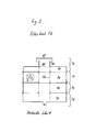
- the filtered water runs through a pipe bend (RB) into the inlet chamber (BEH1), which is open at the top.
- BEH1 pipe bend
- BOH1 pipe bend
- the incoming water flows upwards out of the chamber (BEH1) and is stratified by the warmer temperature in the top of the reservoir, or at fill levels below the height of the chamber (BEH1), the incoming water flows delayed through the holes (BOH1) and with less kinetic energy into the reservoir.
- the dimensioning of the diameter of the bores (BOH1) leads to an overflow and a calming of the newly flowing water in the inlet chamber (BEH1). In the soil area of (BEH1), sediments can sediment.
- the water enters the sampling chamber (BEH2), which is closed at the top, and through the suction pipe (ASZ) or a submersible pump (not shown) mounted in the sampling chamber into the sampling line (SL).
- the selected flow routing ensures stable stratification in the storage tank and prevents mixing.
- the chamber BEH2
- high-quality water free of suspended matter is achieved in all operating situations (even during rainy events), which eliminates the need for subsequent fine filtration.
- the openings (BOH2) are designed according to FIG. 1 so that they form a barrier against floating substances, falling from the inside to the outside.
- the removal chamber (BEH2 there is an electric floatation device (SC) or another level measuring device, the switching status of which is recorded by the central control (ZS).
- the chambers (BEH1) and (BEH2) can, for example, be manufactured inexpensively from commercially available concrete sewer pipes that are vertical (BEH2) is closed by a lid. Instead of the adjusted concrete pipes, the chambers (BEH) can also be replaced by interior walls of the storage container, which are designed accordingly.
- An ultraviolet light source can be provided in the removal chamber to reduce the growth of microorganisms This light source is controlled according to consumption by the central control (ZS).
- the storage container can be made inexpensively of concrete or plastic and form a structural unit with the chambers (BEH) and the filter system (S).
- All lines from or into the storage tank can be routed through a single opening with the wall duct described under point 4.
- the inlet pipe designed to replenish drinking water flows into the inlet pipe (EL) to prevent the sediment being stirred up.
- the storage tank is provided with an overflow line (ÜLF) of small diameter, which is available via a commercially available, low-cost backflow valve for Drinking water and, if necessary, is connected to the interior of the storage tank via a manual or remote thermally operated valve (ASV).
- the valve (ASV) is activated automatically via a remote temperature sensor or manually, depending on ground frost.
- the remote sensor of the thermostatic valve is attached to the outside of the storage tank or the filter system (S). If the ground freezes, the valve opens and the water level in the system is lowered.
- the installation height of the opening (RDE) at the pipe end determines the lower maximum level. This is chosen so that it is at least at the same level or below the freezing depth.
- the rope is led upwards out of the storage container and the weight pulls the pipe end (RDE) down when the rope slackens.
- the pipe section between the pipe end (RDE) and backflow preventer is then expediently designed as a flexible hose.
- the buoyancy protection (AUF) according to FIGS. 1 and 4 consists of a pipe section with connecting pieces for commercially available drainage pipes and a commercially available non-return valve. If the water level outside the storage tank exceeds the specified height, water can flow into the storage tank to compensate the buoyancy when the storage tank is empty and prevent the storage tank from floating.
- the buoyancy protection can also be integrated in the bottom of the storage container, the drainage tube being able to be replaced by a sieve plate which prevents sand, gravel or earth from penetrating into the arrangement.
- the critical height is then determined via the height of a pipe which is led upwards from the backflow preventer in the storage container. This form of buoyancy protection represents an inexpensive protection without having to weigh down the storage container.
- HM soil or clay
- the level in the chamber (BEH2) is recorded by a central control and the feed pump is switched off when the water level falls below a specified minimum.
- the water level in the free area (FA) of the storage tank is checked via a float switch or another device for level measurement, and the drinking water run-on is then controlled via a solenoid valve.
- the pumped operating water quantity is estimated by measuring the pump running time and then the UV lamp in the extraction chamber (BEH2) and the automatic backwashing of the filter system (S) are controlled.
- the water pressure on the pressure side of the pump is controlled by an electro-pneumatic switch by controlling the pump.
- the filter housing can be extended downwards in order to accommodate excess water and, if necessary, drainage water.
- the filter housing with the walls (WB) and the bottom (BB) serves in this case to achieve an enlarged contact area with the gravel fill surrounding the filter housing and the storage container, in order to ensure problem-free seepage in the case of a conductive substrate.
- the filter system can be used as a separate unit for cleaning rain runoff from sealed surfaces, which can then be cleaned and fed to the infiltration or a receiving water.
- a mounting unit that is fully assembled on a frame or a plate and consists of a control system with cabling, shut-off valves, screw connections, pipes, membrane pressure vessels, membrane pressure switches, solenoid valve for drinking water after-running, free drinking water inlet in the make-up line, water meter for rain and drinking water consumption and, if applicable, a feed pump for Installation in buildings enables quick installation on the construction site.
- the peak runoff value of a building with a rainwater harvesting system as described here is considerably lower than with conventional drainage. Canal cross-sections, rainwater retention or treatment basins can thereby be reduced. If the excess water seeps away or is fed into a surface water, the sewer network can be manufactured considerably more cost-effectively.
- Wastewater treatment plants are usually designed for twice the dry weather runoff. Even low rain intensities lead to this value being exceeded.
- the wastewater load, which exceeds twice the dry weather runoff, is channeled past the wastewater treatment plant into the receiving water. This overflow discharge represents an important water polluter. Keeping surface runoff of sealed surfaces from the sewer network is the only way to prevent this contamination of the receiving water.
- the water quality enables the use of detergent formulations without ingredients for water softening.
- the problematic compounds phosphate and NTA no longer get into the wastewater by washing clothes. This relieves wastewater treatment plants and receiving water. In addition to saving drinking water, the consistent use and infiltration of rainwater also has beneficial effects on wastewater disposal.
Landscapes
- Engineering & Computer Science (AREA)
- Life Sciences & Earth Sciences (AREA)
- Hydrology & Water Resources (AREA)
- Water Supply & Treatment (AREA)
- Health & Medical Sciences (AREA)
- Public Health (AREA)
- Environmental & Geological Engineering (AREA)
- Structural Engineering (AREA)
- Chemical & Material Sciences (AREA)
- Organic Chemistry (AREA)
- Sewage (AREA)
- Filtration Of Liquid (AREA)
Abstract
Description
Anlage zur Aufbereitung, Speicherung und Forderung von Regenwasser zur Nutzung als Brauchwasser oder zur Regenwasserbehandlung zum Zwecke der Versickerung oder der Einleitung in einen Vorfluter.Plant for the treatment, storage and supply of rainwater for use as process water or for rainwater treatment for the purpose of seeping away or the discharge into a receiving water.
Die Erfindung betrifft eine Anlage zur Aufbereitung, Speicherung und Forderung von Niederschlagswasser befestigter Flächen wie Dächer, Straßen und Hofplätze zur Nutzung als Brauchwasser in Haushalt, Gewerbe, Industrie und öffentlichen Gebäuden oder zum Zwecke der Versickerung oder Einleitung in einen Vorfluter. Die Anlage besteht hauptsächlich aus Filtersystem mit Sinkstoffabscheider, Speicherbehälter mit Einrichtungen zur Strömungsführung und Sedimentation und einer Steuerungseinheit. Weitere Bestandteile der Anlage sind Einrichtungen zur Füllstandsregulierung, Förderung des Brauchwassers, Anordnungen zur Sicherung gegen Rückstau aus der Kanalisation, Einrichtungen zur Entkeimung und biologischer Fixierung von Schadstoffen, Einrichtungen zum biologischen Abbau von organischen Stoffen, Anordnungen zur Durchführung von Rohren, Leitungen und Kabeln durch Speicherbehälter- und Gebäudewände, Anordnungen zur Auftriebsicherung des Speicherbehälters, Einrichtungen zur Versickerung des Überlaufwassers.The invention relates to a system for the preparation, storage and demand of rainwater paved areas such as roofs, streets and courtyards for use as process water in households, commerce, industry and public buildings or for the purpose of seepage or discharge into a receiving water. The system mainly consists of a filter system with a sediment separator, a storage tank with devices for flow control and sedimentation and a control unit. Other components of the system are facilities for level control, pumping the process water, arrangements for protection against backflow from the sewage system, facilities for the disinfection and biological fixation of pollutants, facilities for the biological degradation of organic substances, arrangements for the implementation of pipes, lines and cables through storage tanks - and building walls, arrangements for securing the buoyancy of the storage tank, facilities for infiltration of the overflow water.
Die Nutzung des Regenwassers von Dachflächen für Brauchwasserzwecke /1/4/, und die Vorreinigung des Regenwassers in einer separaten Filterkammer /1/2/3/5/12/14/ vor dem Vorratsbehälter sind bekannt. Ebenso sind mechanische Oberflächenfilter wie Feinsiebe /2/11/15/16/ und Porenbeton /14/ zur Reinigung des Niederschlagswassers bekannt.The use of the rain water from roof surfaces for industrial water purposes / 1/4 /, and the pre-cleaning of the rain water in a separate filter chamber / 1/2/3/5/12/14 / in front of the storage container are known. Mechanical surface filters such as fine sieves / 2/11/15/16 / and aerated concrete / 14 / for cleaning the rainwater are also known.
Zur Wasserspeicherung werden Beton oder Kunststoffbehälter eingesetzt /2/3/12/14/16/, die im Erdreich oder in Kellerräumen untergebracht sind.Concrete or plastic containers are used for water storage / 2/3/12/14/16 /, which are housed in the ground or in basements.
Bei Regenwassermangel läuft über ein schwimmergesteuertes Ventil im Speicherbehälter Trinkwasser in den Speicherbehälter nach /1/2/4/.If there is a shortage of rainwater, drinking water flows into the storage tank via / a / 2/4 / via a float-controlled valve in the storage tank.
Das Wasser wird aus dem Speicherbehälter meist durch ein sogenanntes Fußventil von einer Pumpe angesaugt, und zu den Verbrauchern weitergeleitet /5/9/16/.The water is usually sucked out of the storage tank through a so-called foot valve by a pump and passed on to the consumers / 5/9/16 /.
Bei den Anlagen zur Aufstellung in Kellerräumen sind Filter, Speicher, Pumpe- und Steuerung teilweise zu einer Montageeinheit zusammengefaßt /1 0/16/. Bei den Anlagen mit Speicher im Erdreich ist als kompakte Bauform die Anordnung /9/ bekannt, bei der Pumpe und Filter oberhalb des Speichers angeordnet sind.In the systems for installation in basements, filters, accumulators, pumps and controls are partly combined to form an assembly unit / 1 0/16 /. The arrangement / 9 / in which the pump and filter are arranged above the reservoir is known as a compact design for systems with underground storage.
Obwohl verschiedene Entwicklungen zurAufbereitung von Regenwasser bekannt sind, ergeben sich in der Praxis mit den bekannten Anlagen eine Reihe von Problemen:
- Die Filtration von Regenwasser über Oberflächenfilter wie Feinsiebe und Gewebe bereitet wegen der schnellen Verstopfung der Filter Probleme. Selbst bei Maschenweiten von 2mm wurde ein rasches Verstopfen der Siebe beobachtet, das durch die Anlagerung und das Verkleben von Feinstoffen verursacht wird. Die Abtrennung der Feinstoffe aus dem Rohwasser ist notwendig um einen Eintrag in den Speicherbehälter zu verhindern, wo diese Stoffe zur Verkeimung bzw. Fäulnis des Reinwassers führen können.
- The filtration of rainwater through surface filters such as fine sieves and fabric causes problems because of the fast blockage of the filter. A rapid blockage of the sieves was observed even with a mesh size of 2 mm, which is caused by the accumulation and sticking of fine materials. The separation of the fine substances from the raw water is necessary in order to prevent an entry into the storage tank, where these substances can lead to contamination or putrefaction of the pure water.
Zur Überwindung des Filterwiderstands ist ein Druck erforderlich der durch die Höhe der Wassersäule über dem Filter gegeben ist. Um einen hohen Füllstand im Speicherbehälter zu realisieren sollte der Filter möglichst weit oben montiert sein. Diese Forderung kollidiert mit der Forderung nach frostsicherer Verlegung der Regenzuleitungen und dem frostsicheren Einbau des Filters. Bei Bodenfrost und Tauwasseranfall durch Sonneneinstrahlung ist ein sicherer Betrieb nicht gewährleistet. Bei Einbau des Speicherbehälters und ggf. des Filters in Kellerräumen ergeben sich Füllstände, die bei üblichen Gebäuden oberhalb des frostfreien Bereichs im Erdreich liegen. Dadurch ist eine Verlegung der Regenzuleitungen im Erdreich außerhalb des Gebäudes nicht möglich.To overcome the filter resistance, a pressure is required which is given by the height of the water column above the filter. In order to achieve a high level in the storage tank, the filter should be mounted as high as possible. This requirement conflicts with the requirement for frost-proof laying of the rain lines and the frost-proof installation of the filter. Safe operation is not guaranteed in the event of frost and condensation caused by sunlight. When the storage tank and, if applicable, the filter are installed in the basement, the fill levels are above the frost-free area in the ground in normal buildings. This means that it is not possible to lay the rain supply lines in the ground outside the building.
Die bekannten Speicherbehälter zum Erdeinbau besitzen keine Sicherung gegen Auftrieb in Grund- oder Stauwasser. Die bekannten Systeme besitzen keine Sicherung gegen Rückstau aus dem Kanalnetz in den Überlauf der Anlagen.The known storage tanks for underground installation have no protection against buoyancy in groundwater or backwater. The known systems have no protection against backflow from the sewer network into the overflow of the systems.
Um beispielsweise den Bedarf an Brauchwasser für Toilette, Waschmaschine und Garten eines Einfamilienhauses zu erreichen, muß das gesamte Dachablaufwasser des Gebäudes erfasst werden. Die anfallenden Niederschläge entsprechen in Mitteleuropa etwa dem Bedarf an Brauchwasser. Dies ist bei den bekannten Filtern nicht gewährleistet, weil die Abflüsse eines z. B. 100m2 grossen Daches (in die Waagrechte projezierte Grundfläche) die Durchflußkapazität der bekannten Systeme auch bei sauberem Filter zeitweise überschreiten. Durch die zunehmende Beladung des Filters mit Schmutz geghen so erhebliche Wassermengen der ohne Nutzung verloren.For example, in order to meet the need for service water for the toilet, washing machine and garden of a single-family home, the entire roof drain water of the building must be recorded. The precipitation that occurs in Central Europe corresponds approximately to the need for process water. This is not guaranteed in the known filters because the outflows of a z. B. 100m 2 large roof (projected into the horizontal base area) temporarily exceed the flow capacity of the known systems even with a clean filter. Due to the increasing loading of the filter with dirt, considerable amounts of water are lost without being used.
Die Nachteile der bekannten Systeme sind im folgenden einzeln aufgeführt:
- Nachteile der Filtersysteme:
- Bei den bekannten Filtern, die im Erdreich eingegraben werden /2/3/12/, erfolgt der Wassereintritt oben in die Filterkammer, um dann über einen Siebeinsatz und ggf. ein Filtervlies oder eine Filterschüttung lotrecht nach unten abzufließen. Die Frostsicherheit dieser Systeme ist nicht gewährleistet, weil die Zuleitungen von den Fallrohren der Dachflächen eines Gebäudes zum Filter oberflächennah verlegt werden müssen, um den Durchlauf des Wassers von oben nach unten durch den Filter zu ermöglichen. Der Winterbetrieb dieser Filter ist deshalb nicht sichergestellt. Bei Einbau der Zuleitungen in frostsichere Tiefe im Boden, würde der Auslauf des Filters wegen des notwendigen Gefälles sehr tief zu liegen kommen, und deshalb müßte auch der Speicherbehälter tiefer eingebaut werden, wodurch die Baukosten ansteigen.
- Disadvantages of the filter systems:
- With the known filters that are buried in the ground / 2/3/12 /, the water enters at the top into the filter chamber, in order to then flow downwards vertically via a sieve insert and, if necessary, a filter fleece or a filter bed. The frost resistance of these systems is not guaranteed because the supply lines from the downpipes of the roof surfaces of a building to the filter must be laid close to the surface to allow the water to pass through the filter from top to bottom. The winter operation of these filters is therefore not guaranteed. If the supply lines were installed in the ground in a frost-proof depth, the outlet would of the filter have to lie very low due to the necessary gradient, and therefore the storage tank would also have to be installed lower, which increases the construction costs.
Die wirksame Filterfläche dieser Filter wird durch den waagrechten Querschnitt der Filterkammer bestimmt. Dadurch ergeben sich relativ kleine effektive Filterflächen im Verhältnis zum Flächenverbrauch und der Baugröße der Filterkammer /2/3/5/12/14/.The effective filter area of these filters is determined by the horizontal cross section of the filter chamber. This results in relatively small effective filter areas in relation to the area used and the size of the filter chamber / 2/3/5/12/14 /.
Zur Überwindung des Filterwiderstandes steht die Druckhöhe der Wassersäule über dem Filter zu Verfügung, weil die Filter von oben nach unten durchströmt werden. Dadurch ergeben sich nur geringe nutzbare Überstauhöhen. Bei der Anordnung /14/ werden nur grobe Stoffe zurückgehalten, der Filterkorb hat eher die Funktion eines Rechens.The pressure head of the water column above the filter is available to overcome the filter resistance because the filter flows through from top to bottom. As a result, there are only small usable overflow levels. With arrangement / 14 / only coarse substances are retained, the filter basket has more the function of a rake.
Regenwasser enthält nach Trockenperioden einen hohen Feststoffanteil. Dadurch verstopfen die bekannten Oberflächenfilter /2/7/8/ relativ schnell und der Filterwiderstand steigt nach geringer Standzeit an. Die selbstreinigenden Anordnungen /11/15/ zum Einbau in Regenfallrohre neigen wegen der besonderen Eigenschaften der im Regenwasserenthaltenen Stoffe, wie Pollen, zeitweise ebenfalls zum Verstopfen, da die Poren durch Anlagerung von Feinstoffen mit der Zeit verkleben.After dry periods, rainwater contains a high proportion of solids. As a result, the known surface filters / 2/7/8 / clog relatively quickly and the filter resistance increases after a short service life. The self-cleaning arrangements / 11/15 / for installation in downpipes also tend to clog from time to time because of the special properties of the substances contained in the rainwater, such as pollen, since the pores stick with time due to the accumulation of fine substances.
Dementsprechend sind Wartungs- und Reinigungsaufwand hoch und der Verlust an nutzbarem Rohwasser wegen Verstopfung und Überlaufen der Filter hoch.Accordingly, maintenance and cleaning efforts are high and the loss of usable raw water due to clogging and overflow of the filters is high.
Regenereignisse treten mit unterschiedlichen Intensitäten auf und verursachen deshalb temporär hohe Abflußspitzen. Bei Starkregenereignissen wird deshalb die Durchflußleistung der bekannten Filterkonstruktionen überschritten, so daß die Filter überlaufen und Niederschlagswasser für die Nutzung verloren geht. Diesen Nachteil weisen auch die angebotenen Filtersammler /11/15/ und Abzweige /13/ zum Einbau in die Fallrohre auf. Der Anteil des nutzbaren Niederschlagswassers und damit die Wirtschaftlichkeit wird deshalb entscheidend reduziert.Rain events occur with different intensities and therefore temporarily cause high discharge peaks. In heavy rain events, the flow rate of the known filter designs is therefore exceeded, so that the filters overflow and rainwater is lost for use. The filter collectors / 11/15 / and branches / 13 / for installation in the downpipes also have this disadvantage. The proportion of usable rainwater and thus the economic efficiency is therefore significantly reduced.
Die bekannten Filter mit Filterschüttung /2/3/5/ sind nur umständlich zu reinigen, weil Vorkehrungen zur rationellen Entnahme der Schüttung fehlen. Einsätze aus Mineralfasern, Kunststoffvliesen o.ä. sind nicht regenerierbar und müssen nach Verschmutzung ersetzt werden. Die geringe Schichtdicke und der geringe Querschnitt der Filterschüttung im Verhältnis zur Baugröße des Filters gewährleistet nur begrenzte Reinigung; Absetzbare, gröbere Stoffe wie Moos, Laub und Vogelkot werden bei den Filtern /2/3/5/9/10/12/ in den Filter eingetragen und verstopfen diesen vorzeitig.The known filters with filter bed / 2/3/5 / can only be cleaned with great difficulty because there are no precautions for rational removal of the bed. Inserts made of mineral fibers, plastic fleece or similar cannot be regenerated and must be replaced after contamination. The small layer thickness and the small cross-section of the filter bed in relation to the size of the filter ensures only limited cleaning; Removable, coarser substances such as moss, leaves and bird droppings are entered into the filter / 2/3/5/9/10/12 / and clog the filter prematurely.
Der Zulauf des Regenwassers bei den bekannten Filtern muß von oben erfolgen; Dadurch kann wegen des notwendigen Gefälles der Regenleitungen im Erdreich oft nur das Wasser aus einem Fallrohr je Filter genutzt werden; Der Filter muß aus diesem Grund in der Nähe des Fallrohres installiert werden.The rainwater in the known filters must be supplied from above; Because of the necessary slope of the rain pipes in the ground, this means that often only the water from one downpipe per filter can be used; For this reason, the filter must be installed near the downpipe.
Die erdverlegten Entwässerungsleitungen zwischen Fallrohren und Filter können nicht vorschriftsgerecht im frostfreien Bodenbereich verlegt werden ohne die Einbautiefe von Speicher und Filter wegen des notwendigen Fließgefälles stark zu erhöhen.The underground drainage pipes between the downpipes and the filter cannot be laid correctly in the frost-free floor area without greatly increasing the installation depth of the storage tank and filter due to the necessary flow gradient.
Die bekannten Regensammler /11/13/15/ zur Montage im Fallrohr ermöglichen zwar die Fassung des Regenwassers von mehreren Fallrohren und die Einleitung in einen einzigen Filterschacht bzw. direkt in ein Gebäude bei entsprechendem Gefälle ohne die Gefahr des Einfrierens. Durch die Konstruktion dieser Regensammler und den geringen Querschnitt der Ableitung gehen jedoch beträchtliche Wassermengen bei Starkregenereignissen verloren. Dadurch verschlechtert sich der Deckungsgrad und die Wirtschaftlichkeit; (Deckungsgrad = genutztes Brauchwasser/gesamtes verbrauchtes Wasser). Zusätzlich zu den vorhandenen Regenentwässerungsleitungen sind weitere Leitungen zurAbleitung des nutzbaren Regenwassers notwendig.The well-known rain collectors / 11/13/15 / for mounting in the downpipe allow rainwater to be drawn from several downpipes and to be discharged into a single filter shaft or directly into a building on a corresponding slope without the risk of freezing. However, due to the construction of these rain collectors and the small cross-section of the drainage, considerable amounts of water are lost in heavy rain events. As a result, the degree of coverage and the economy deteriorate; (Degree of coverage = used water / total water used). In addition to the existing rainwater drainage pipes, further pipes are required to drain the usable rainwater.
Dadurch entstehen Mehrkosten.This creates additional costs.
Die bekannten Speichersysteme besitzten folgende Nachteile:
- Die Aufwirbelung des Bodensatzes im Speicherbehälter der in /5/8/9/10/12/16/ beschriebenen Anlagen ist unter ungünstigen Betriebsbedingungen wie geringer Wasserstand und während Starkregenereignissen möglich und führt zur Verschmutzung des entnommenen Brauchwassers.
- The swirling up of the sediment in the storage tank of the systems described in / 5/8/9/10/12/16 / is possible under unfavorable operating conditions such as low water level and during heavy rain events and leads to contamination of the used water.
Die Wasserentnahme während eines, Regenereignisses wird bei den genannten Systemen /5/8/9/10/12/16/ nicht berücksichtigt; Das frisch einlaufende, schmutzige Wasser durchmischt sich mit dem gespeicherten und durch Sedimentation gereinigten, schwebstoffreien Wasser. Deshalb muß in der Reinwasserleitung auf der Druckseite ein Feinfilter vorgesehen werden, der Mehrkosten verursacht, zur Verstopfung neigt und zum Nährboden für Mikroorganismen wird. Dadurch verschlechtert sich die Qualität des Reinwassers durch ständige Verkeimung dauerhaft.The withdrawal of water during a rain event is not taken into account in the systems mentioned / 5/8/9/10/12/16 /; The freshly entering, dirty water mixes with the stored, sediment-free, suspended water. Therefore, a fine filter must be provided in the pure water pipe on the pressure side, which causes additional costs, tends to clog and becomes a breeding ground for microorganisms. As a result, the quality of the pure water deteriorates permanently due to constant contamination.
Bei gering gefülltem Speicher des Systems /8/ steht nur geringer oder kein Druck zur Filtration zu Verfügung.If the system / 8 / memory is low, there is little or no pressure available for filtration.
Die Speicher- und Filtereinheit wie in DE3825310 beschrieben, besitzt folgende Nachteile:
- Speicher und Filter bilden eine Einheit. Die Filtration findet nur bei Entnahme, also nach der Speicherung statt. Sedimentierte Schmutzstoffe liegen am Speicherboden und führen zur Verkeimung und evtl. Fäulnis des überstehenden Wassers; Bei der Füllung des Speichers mischt sich der gesamte Speicherinhalt durch;
- Die Wasserentnahme während eines Regenereignisses wurde nicht berücksichtigt, (Durchmischung von sedimentiertem, sauberen mit neu einlaufendem, schmutzigem Wasser).
- Memory and filter form one unit. Filtration only takes place after removal, i.e. after storage. Sedimented contaminants lie on the storage floor and lead to the contamination and possible rotting of the excess water; When the memory is filled, the entire contents of the memory mix;
- The water withdrawal during a rain event was not taken into account (mixing of sedimented, clean with newly arriving, dirty water).
Bei gering gefülltem Speicher steht nur geringer oder kein Druck zur Filtration zur Verfügung.If the storage is low, there is little or no pressure available for filtration.
Der Filter wirkt als Oberflächenfilter und wird dadurch schnell von Schmutzstoffen zugesetzt.The filter acts as a surface filter and is therefore quickly clogged by contaminants.
Der Filter ist nicht regenerierbar oder rückspülbar.The filter cannot be regenerated or backwashed.
Bei Wasserüberschuß und gefülltem Speicher läuft das überschüssige Wasser durch den Speicher hindurch und lädt dort das Sediment ab. Dadurch wird der Speicher zusätzlich mit Schmutzstoffen beladen.If there is excess water and the reservoir is full, the excess water runs through the reservoir and unloads the sediment there. This means that the storage tank is also loaded with contaminants.
Die Frosteinwirkung wurde bei diesem System nicht berücksichtigt.The frost effect was not considered in this system.
Zusammenfassend läßt sich sagen, der bisherige Stand der Technik zur Nutzung von Regenwasser stellt hohe Anforderungen an den Betreiber der Anlage, wegen der häufigen und aufwendigen Reinigung der Filter und der beschränkten Wasserqualität. Eine ausreichende Wasserqualität zur Nutzung des gewonnen Brauchwassers z.B. zum Wäschewaschen kann nicht dauerhaft garantiert werden.In summary, it can be said that the current state of the art for the use of rainwater places high demands on the operator of the system, because of the frequent and time-consuming cleaning of the filters and the limited water quality. Adequate water quality for the use of the used water e.g. washing clothes cannot be guaranteed permanently.
Die Verluste an nutzbarem Regenwasser bei der Filtration setzen den Deckungsgrad der Brauchwasserversorgung stark herab, die Anlagenkosten sind deshalb hoch im Verhältnis zum eingesparten Trinkwasser, die Bedarfsdeckung ist gering.The losses of usable rainwater during filtration greatly reduce the degree of coverage of the hot water supply, the system costs are therefore high in relation to the drinking water saved, and the demand coverage is low.
Die bekannten Systeme besitzen teilweise einen Überlauf zum Kanalnetz, der nicht gegen Rückstau gesichert ist.Some of the known systems have an overflow to the sewer network, which is not secured against backflow.
Dies verstößt in Deutschland gegen geltende Normen (DIN 1986).This violates applicable standards in Germany (DIN 1986).
Die geringe Betriebssicherheit, der hohe Wartungsbedarf, die unsichere Wasserqualität dieser Anlagen und die nicht normgerechte Verlegung der Entwässerungsleitungen verwehren den Handwerksbetrieben des Sanitärfachs bisher, die Technik der Regenwassernutzung anzubieten.The low level of operational safety, the high maintenance requirements, the unsafe water quality of these systems and the non-standard laying of the drainage pipes have so far prevented the handicraft companies in the sanitary subject from offering the technology of rainwater harvesting.
Quellen und Bezüge:
- /1/ Broschüre des Hessischen Ministerium für Umwelt und Reaktorsicherheit: "Regenwassernutzung in privaten und öffentlichen Gebäuden". Wiesbaden 1989, Deutschland.
- /2/ Prospekt Fa. Wagner & Co GmbH Solartechnik, Zimmermannstr. 1, D-3550 Marburg;
- /3/ Prospekt der Fa. Otto Graf GmbH, Carl-Zeiss-Str. 2-6, D-7835 Teningen;
- /4/ Wolfgang Bredow: "Regenwassersammelanlage", 8. Auflage 1988, Ökobuch Verlag, Staufen/D-7800 Freiburg.
- /5/ Offenlegungsschrift DE 3819330, Deutschland.
- /6/ Offenlegungsschrift DE 3927042, Deutschland.
- /7/ Offenlegungsschrift DE 3821633, Deutschland.
- /8/ Offenlegungsschrift DE 3825310, Deutschland.
- /9/ Gebrauchsmuster GM 78 27 765, Deutschland.
- /10/ Gebrauchsmuster G 89 13 810.4, Deutschland.
- /11/ Prospekt "Wilo-Filtersammler für die perfekte Regenwassernutzung" der Fa. Wilo GmbH, Nortkirchenstr. 100, D-4600 Dortmund 30.
- /12/ Prospekt "Die Paradigma Regenwasser-Sammelanlage" der Fa. Ritter Energie- und Umwelttechnik GmbH & Co. KG, Kallhardtstr. 30, D-7530 Pforzheim.
- /13/ Prospekt "Regensammler mit Füllautomatik" der Fa. Speidel Tank- und Behälterbau GmbH, Tübinger Str. 14, Postfach 28, D-7404 Ofterdingen-Tübingen.
- /14/ Prospekt "Regenwassersammelschächte mit vorgeschaltetem Laub- und Sandfang" der Fa. Kießling Beton GmbH, Hauptstr. 6, D-8581 Seybottenreuth.
- /15/ Prospekt "Der WISY Filtersammler" baugleich mit /11/.
- /16/ Prospekt "Regenwasser nutzen" der Fa. OSNA - J. Hartlage GmbH & Co. KG, Postfach 2240, Brückenstr. 3, D4500 Osnabrück.
- / 1 / Brochure of the Hessian Ministry for the Environment and Nuclear Safety: "Use of rainwater in private and public buildings". Wiesbaden 1989, Germany.
- / 2 / Brochure from Wagner & Co GmbH Solartechnik, Zimmermannstr. 1, D-3550 Marburg;
- / 3 / Brochure from Otto Graf GmbH, Carl-Zeiss-Str. 2-6, D-7835 Teningen;
- / 4 / Wolfgang Bredow: "Regenwassersammelanlage", 8th edition 1988, Ökobuch Verlag, Staufen / D-7800 Freiburg.
- / 5 / published application DE 3819330, Germany.
- / 6 / Offenlegungsschrift DE 3927042, Germany.
- / 7 / DE 3821633, Germany.
- / 8 / published application DE 3825310, Germany.
- / 9 / Utility model GM 78 27 765, Germany.
- / 10 / Utility model G 89 13 810.4, Germany.
- / 11 / Brochure "Wilo filter collector for the perfect use of rainwater" from Wilo GmbH, Nortkirchenstr. 100, D-4600 Dortmund 30.
- / 12 / Brochure "The paradigm rainwater collection system" from Ritter Energie- und Umwelttechnik GmbH & Co. KG, Kallhardtstr. 30, D-7530 Pforzheim.
- / 13 / Brochure "Rain collector with automatic filling" from Speidel Tank- und Behälterbau GmbH, Tübinger Str. 14, Postfach 28, D-7404 Ofterdingen-Tübingen.
- / 14 / Brochure "Rainwater collecting shafts with upstream leaf and sand trap" from Kießling Beton GmbH, Hauptstr. 6, D-8581 Seybottenreuth.
- / 15 / Brochure "The WISY filter collector" identical to / 11 /.
- / 16 / "Use rainwater" brochure from OSNA - J. Hartlage GmbH & Co. KG, Postfach 2240, Brückenstr. 3, D4500 Osnabruck.
Die hier neu vorgestellte Anlage besitzt folgende Merkmale:
- 1. Filtration des Regenwassers vor der Speicherung über wartungsfreundliches Filtersystem mit einfach regenerierbarer Filtermasse ohne Verschleißteile.
- 2. Sedimentation von Schmutzstoffen vor der Filtration.
- 3. Filtration ohne Verlust an Fließhöhe durch variablen Überstau des Filters und Zunahme der wirksamen Filterfläche in Abhängigkeit des Flusses.
- 4. Optimales Verhältnis von Filterleistung und Baugröße des Filters durch koaxiale, rotationssymmetrische Bauweise.
- 5. Geringer Wartungs- und Reinigungsbedarfdes Filtersystems durch hohe Rückhaltekapazität bei kompakter Bauweise.
- 6. Geringer Filterwiderstand bei hoher Reinigungsleistung.
- 7. Frostsichere und vorschriftsgerechte Verlegung der Zuleitungen im Erdreich zum Filter ist möglich, ohne daß der maximale Füllstand im Speicherbehälter dadurch erniedrigt wird.
- 8. Sicherer Winterbetrieb.
- 9. Der Anschluß mehrerer Dachflächen und weit auseinanderliegender Fallrohre an eine einzige Filtereinheit ist möglich.
- 10. Kein Verlust an Rohwasser durch überlastete oder verstopfte Filter, dadurch maximaler Deckungsgrad und hohe Wirtschaftlichkeit.
- 11. Anpassung der Filterleistung an unterschiedlichen Bedarf durch Kombination mehrerer Standard-Filterelemente in Modulbauweise in einem Filtergehäuse.
- 12. Strömungsführung und Schichtung des Reinwassers im Speicherbehälter, dadurch Abscheidung von Trübstoffen, die durch Filtration nicht entfernt werden konnten.
- 13. Vollständige Entfernung von Schwebstoffen mittels Sedimentation durch Trennung von frisch einlaufendem und älterem, gespeicherten Wasser im Speicherbehälter; ständiger Vorrat an triibstofffreiem Wasser, dadurch Gewährleistung gleichbleibend hoher Wasserqualität.
- 14. Keine weiteren Feinfilter in der Druckleitung notwendig.
- 15. Selbsttätige Begrenzung des maximalen Füllstands im System in Abhängigkeit der Bodentemperatur; dadurch Erhöhung des Speichervolumens in der frostfreien Zeit.
- 16. Rückstaugesicherter Anschluß des Überlaufs an die Kanalisation, dadurch Erfüllung der DIN 1986 (Deutschland).
- 17. Sicherung des Speicherbehälters gegen Auftrieb in Grund- und Stauwasser.
- 18. Spezielle Rohr- und Leitungsdurchführungen für Gebäude und Behälterwände.
- 19. Biologische Fixierung von Schadstoffen und Nährstoffen im Bodensediment.
- 20. Entkeimung des Wassers durch UV Bestrahlung und Ozonentwicklung.
- 21. Schneller und kostengünstiger Einbau des Systems auf der Baustelle durch kompakte Bauweise mit anschlußfertigen Komponenten.
- 1. Filtration of the rainwater before storage via a maintenance-friendly filter system with an easily regenerable filter mass without wearing parts.
- 2. Sedimentation of contaminants before filtration.
- 3. Filtration without loss of flow height through variable filter overflow and increase of the effective filter area depending on the flow.
- 4. Optimal ratio of filter performance and size of the filter due to coaxial, rotationally symmetrical design.
- 5. Low maintenance and cleaning requirements of the filter system due to high retention capacity with a compact design.
- 6. Low filter resistance with high cleaning performance.
- 7. Frost-free and correct laying of the supply lines in the ground to the filter is possible without reducing the maximum fill level in the storage tank.
- 8. Safe winter operation.
- 9. The connection of several roof areas and widely spaced downpipes to a single filter unit is possible.
- 10. No loss of raw water due to overloaded or clogged filters, thereby maximum coverage and high efficiency.
- 11. Adaptation of the filter performance to different needs by combining several standard filter elements in modular design in one filter housing.
- 12. Flow guidance and stratification of the pure water in the storage tank, thereby separating turbid substances that could not be removed by filtration.
- 13. Complete removal of suspended matter by means of sedimentation by separating freshly incoming and older, stored water in the storage tank; permanent supply of non-fuel water, thereby guaranteeing consistently high water quality.
- 14. No further fine filters in the pressure line necessary.
- 15. Automatic limitation of the maximum level in the system depending on the floor temperature; thereby increasing the storage volume in the frost-free period.
- 16. Backflow-proof connection of the overflow to the sewage system, thereby fulfilling DIN 1986 (Germany).
- 17. Securing the storage tank against buoyancy in groundwater and backwater.
- 18. Special pipe and line bushings for buildings and container walls.
- 19. Biological fixation of pollutants and nutrients in soil sediment.
- 20. Disinfection of the water by UV radiation and ozone development.
- 21. Fast and inexpensive installation of the system on the construction site due to compact design with ready-to-connect components.
Das Regenwasser strömt gemäß Fig. 1 von den normgerecht in frostsicherer Tiefe verlegten Entwässerungsleitungen (ENT) im unteren Bereich durch mehrere Einlaufanschlüsse (z.B. KG Steckmuffen) in das Filtersystem (S) nach Fig. 2 ein, die Strömungsgeschwindigkeit verringert sich in einer Sedimentationszone (SZ), grobe Schmutzteilchen sedimentieren in einer eingesetzten, herausnehmbaren Bodentasse (TS) die aus dem Boden (B) des Filtergehäuses (FIG) steht, das Wasser strömt dann zwischen den Gehäusewänden (FIG) und den koaxialen, zylindrisch ausgebildeten perforierten Wänden des Filterkorbs (FK) hoch, durch die Perforation des Filterkorbs FK hindurch senkrecht zum Filterkorb durch eine Filtermasse (FS), dann über das innere perforierte Rohr (FR) zum Abgang (AG). Bei Starkregenereignissen strömt das Wasser über den Bypass (BY) an der Filterschüttung vorbei direkt zum Abgang (AG), wobei Schwimmstoffe wie Pollen durch den als Tauchhülse ausgebildeten Hut (HT) am Abfließen gehindert werden. Grobe Stoffe werden durch ein steckbares Grobsieb (GS) zurückgehalten.According to FIG. 1, the rainwater flows from the drainage pipes (ENT) laid in accordance with the standards in a frost-proof depth in the lower area through several inlet connections (e.g. KG push-in sockets) into the filter system (S) according to FIG. 2, the flow speed is reduced in a sedimentation zone (SZ ), coarse dirt particles sediment in an inserted, removable bottom cup (TS) which stands out of the bottom (B) of the filter housing (FIG), the water then flows between the housing walls (FIG) and the coaxial, cylindrical perforated walls of the filter basket (FK ) high, through the perforation of the filter basket FK perpendicular to the filter basket through a filter mass (FS), then over the inner perforated tube (FR) to the outlet (AG). In the event of heavy rain events, the water flows via the bypass (BY) past the filter bed directly to the outlet (AG), whereby floating substances such as pollen are prevented from flowing off by the hat (HT) designed as an immersion sleeve. Coarse substances are retained by a pluggable coarse sieve (GS).
Dieser Bypass (BY) trägt der Tatsache Rechnung, daß es bei wirtschaftlich vernünftigen Dimensionierungen des Filters nicht möglich ist, Starkregenabflüsse vollständig durch ein Filter zu leiten. Versuch haben gezeigt, daß es darüber hinaus nicht notwendig ist, diese Starkregenabflüsse zu filtrieren, da sie keine relevante Schmutzfracht tragen, weil die auf den Dachflächen liegende atmosphärische Trockendeposition bis zum Erreichen des Spitzenabflusses schon abgespült worden ist. In Anhängigkeit des Flusses kann das Rohwasser also bei extrem starken Regenereignissen ohne Verluste direkt in den Speicherbehälter (VB) gelangen. Der Filterkorb (FK) kann auch mit vieleckigem Querschnitt ausgeführt werden, z. B. in Form eines Faltenfilters um die Oberfläche noch zu vergrößern. Ebenso sind parallele Filterwände möglich. An Stelle des Rohres (FR) tritt dann eine zweite zur Filterwand (FK) parallele Filterwand. Der Filterkorb kann steckbar in einer konischen oder zylindrischen Muffe (MF) befestigt sein, wobei die bekannten Abdichtungen von handelsüblichen Kanalrohren zur Anwendung kommen können. Ebenso ist eine flachdichtende Ausführung möglich, bei der der Korb auf dem Sockel (BF) zuliegen kommt, ggf. mit einer zwischengelegten elastischen Dichtung.This bypass (BY) takes into account the fact that, with economically reasonable dimensions of the filter, it is not possible to conduct heavy rain drains completely through a filter. Experiments have shown that it is also not necessary to filter these heavy rain drains, since they do not carry any relevant dirt, because the atmospheric dry deposition on the roof surfaces has already been rinsed off before the peak drain is reached. Depending on the river, the raw water can reach the storage tank (VB) without losses in the event of extremely heavy rain events. The filter basket (FK) can also be designed with a polygonal cross-section, e.g. B. in the form of a pleated filter to enlarge the surface. Parallel filter walls are also possible. The pipe (FR) is then replaced by a second filter wall parallel to the filter wall (FK). The filter basket can be plugged into a conical or cylindrical sleeve (MF), whereby the known seals of commercially available sewer pipes can be used. A flat-sealing version is also possible, in which the basket comes to rest on the base (BF), if necessary with an interposed elastic seal.
Die Konstruktion des Filtersystems ergibt sich aus der Tatsache, daß Abflüsse mit unregelmäßiger Verteilung und Abflußspitzen durch Gewitterregen simultan gereinigt werden müssen. Dies ist nur über ein Tiefenfilter zu realisieren, das eine hohe Schmutzfracht bei geringem Filterwiderstand aufnehmen kann, ohne zu verstopfen. Oberflächenfilter wie Feinsiebe scheiden aus, weil sie bereits durch ein einziges Regenereignis verstopft werden können. Die Vorschaltung einer Sedimentationszone (SZ) vor den eigentlichen Filter, hält schnell sedimentierbare Stoffe, die einen Hauptteil der gesamten Schmutzfracht ausmachen, aus dem Filter fern, so daß sich lange Reinigungsintervalle und Standzeiten des Filters ergeben. Durch die koaxiale- zylindrische Bauweise der Filtereinheit ergeben sich günstige Verhältnisse zwischen Filterleistung und Baugröße. Versuche haben gezeigt, daß eine hohe Filtrationsleistung entscheidend durch den durchströmten Querschnitt der Filterschüttung FS gesteuert wird, nicht so sehr durch die Schichtdicke von (FS). Durch die koaxiale Anordnung wird eine hohe Mantelfläche der Filterschüttung erzielt, entsprechend einem großen durchströmten Querschnitt, bei gleichzeitig geringem Filterwiderstand. Durch faltenförmige Ausbildung der senkrechten perforierten Wände des Filterkorbs (FR) und (FK) läßt sich die Mantelfläche weiter vergrößern, bei gleicher Baugröße der Filterkammer (FIG).The design of the filter system results from the fact that outflows with irregular distribution and outflow peaks have to be cleaned simultaneously by thunderstorm rain. This can only be achieved with a depth filter, which can absorb a high dirt load with a low filter resistance without clogging. Surface filters such as fine sieves are ruled out because they can be blocked by a single rain event. The connection of a sedimentation zone (SZ) before the actual filter stops quickly sedimentable substances, which make up a major part of the total dirt load, away from the filter, so that long cleaning intervals and service life of the filter result. The coaxial-cylindrical design of the filter unit results in favorable relationships between filter performance and size. Experiments have shown that a high filtration rate is decisively controlled by the cross-section of the filter bed FS, not so much by the layer thickness of (FS). Due to the coaxial arrangement, a large lateral surface of the filter bed is achieved, corresponding to a large cross-section with flow, and at the same time a low filter resistance. By forming the vertical perforated walls of the filter basket (FR) and (FK) in the form of folds, the outer surface can be enlarged further, with the same size of the filter chamber (FIG).
Die Filterschüttung (FS) besteht aus körnigem, gerundetem oder scharf gebrochenem Material. Zur Anwendung kommt Tonganulat, Blähtonsplitt, Ziegelbruch, vulkanische oder industrielle Schlacken, Bims- oder Tuffstein, Naturgesteins-Splitt oder -Kies, Kunststoffgranulat, Aktiv- oder Holzkohle, Holz oder Rinde. Dabei kann die Abgabe von bioziden Substanzen etwa aus Rinde oder Holz ein Wachstum von Mikroorganismen beschränken.The filter bed (FS) consists of granular, rounded or sharply broken material. Clay granulate, expanded stone chippings, broken bricks, volcanic or industrial slag, pumice or tufa, natural stone chippings or gravel, plastic granules, activated or charcoal, wood or bark are used. The release of biocidal substances from bark or wood, for example, can limit the growth of microorganisms.
Das Wasser wird bei Durchlaufen des Reinigungsschachtes in der Reihenfolge Sedimentation in der Zone (SZ), Siebung durch den Filterkorb (FK) und Tiefenfiltration in der Schüttung (FS) gereinigt; Am Filterkorn der Filtermasse (FS) werden Partikel und Schwebstoffe adsorbiert; Dadurch können Feinstoffe zurückgehalten werden, die kleiner sind als die Porenweite des Filters ohne dabei den Filterwiderstand durch Verstopfen der Poren zu erhöhen. Versuche haben gezeigt, daß sich mit zunehmender Filterstandzeit auf dem Filterkorn Häutchen ausbilden, durch die Anlagerung von feinsten Schmutzstoffen; Diese Häutchen lösen sich bei Bewegen und Spülen des Filterkorns in großen Flocken ab, und sind dadurch schnell sedimentierbar; Dadurch ist die Filterschüttung schnell und preisgünstig regenerierbar durch Rückspülung oder Herausnehmen und Abspritzen der Filterschüttung mit Wasser. Das z.B. von den Regenfallrohren kommende Ablaufwasser staut sich je nach Abflussintensität in den Zulaufleitungen bis zur Höhe des Bypasses (BY) auf. Diese hydrostatische Druckhöhe wird zur Überwindung des Filterwiderstandes genutzt.The water is cleaned as it passes through the cleaning shaft in the order of sedimentation in the zone (SZ), sieving through the filter basket (FK) and deep filtration in the bed (FS); Particles and suspended matter are adsorbed on the filter grain of the filter mass (FS); As a result, fine substances that are smaller than the pore size of the filter can be retained without increasing the filter resistance by clogging the pores. Experiments have shown that, with increasing filter service life, pimples form on the filter grain due to the accumulation of the finest contaminants; These cuticles come off in large flakes when the filter grain is moved and rinsed, and can therefore be sedimented quickly; As a result, the filter bed can be regenerated quickly and inexpensively by backwashing or removing and spraying the filter bed with water. That e.g. Depending on the intensity of the discharge, drain water coming from the downpipes accumulates in the supply lines up to the bypass height (BY). This hydrostatic pressure level is used to overcome the filter resistance.
Der wirksame Filterquerschnitt paßt sich deshalb dem Volumenstrom des einlaufenden Wassers an: Mit steigendem Durchfluß und steigendem Filterwiderstand steigt der Wasserspiegel (WS) im Einlaufbereich (EB) an, und dadurch auch der durchflossene Filterquerschnitt. Durch den variablen Überstau in den Zulaufleitungen steht ein ausreichender Druck zur Filtration zur Verfügung, bei frostsicherer, normgerechter Verlegung der Zuleitungen und einem Ruhewasserstand unter Frosttiefe, ohne daß Füllhöhe im Speicher (VB) verloren geht. Bei Überstau des Filterkorbs (FK) während eines Regenereignisses übersteigt der Wasserstand in den Zulaufleitungen zwar die frostfreie Tiefe; Zum Überstau führen jedoch nur Starkregenereignisse, die erfahrungsgemäß bei Bodenfrost nicht auftreten können; Die Frostsicherheit ist dadurch zu jeder Jahreszeit gewährleistet.The effective filter cross-section therefore adapts to the volume flow of the incoming water: With increasing flow and increasing filter resistance, the water level (WS) in the inlet area (EB) rises, and with it the flow through the filter cross-section. Due to the variable overflow in the supply lines, sufficient pressure is available for filtration, with frost-proof, standard-compliant routing of the supply lines and a still water level below frost depth, without the fill level in the storage tank (VB) being lost. If the filter basket (FK) is flooded during a rain event, the water level in the supply lines will exceed the frost-free depth; However, only heavy rain events, which experience has shown that cannot occur in ground frost, lead to flooding; Frost protection is guaranteed in every season.
Der Filterkorb (FK) ist steckbar oder mit Gewinde oder mit Bajonettverschluß in einer Muffe (MF) befestigt, so daß zur Reinigung der Filterschüttung (FS) der ganze Filterkorb herausgenommen und entleert werden kann. Die Rohranschlüsse des Filtergehäuses sind als Steckmuffen oder Rohrnippel-Steckenden ausgebildet, so daß konventionelle Entwässerungsleitungen genormter Nennweiten durch Einstecken sofort angeschlossen werden können.The filter basket (FK) can be plugged in or fastened in a sleeve (MF) with a thread or with a bayonet lock so that the entire filter basket can be removed and emptied for cleaning the filter bed (FS). The pipe connections of the filter housing are designed as push-in sockets or pipe nipple plug ends, so that conventional drainage pipes of standardized nominal widths can be connected immediately by plugging them in.
Die Körngrößenverteilung der Filterschüttung kann mit der Höhe variieren, zur Erzielung einer gleichmäßigen Filtergeschwindigkeit;The grain size distribution of the filter bed can vary with the height in order to achieve a uniform filter speed;
Im Bodenbereich unterhalb der Filterschüttung kann eine Rohrleitung (RSL) zur Rückspülung der Filterschüttung angeordnet werden; Der Einlauf dieser Rückspülleitung (RSL) kann nach oben in den Bereich (BY) herausgeführt und mit einem Verschraubungsflansch versehen werden oder steckbar im Sockel (BF) angeschlossen sein. Zur Rückspülung wird dort mit einem Schlauch oder über eine ortsfeste Rohrleitung Wasser eingespeist. Im Überlauf (UE) befindet sich ein herausnehmbares Absperrgitter (ABS) zum Schutz gegen aus dem Kanalsystem eindringende Tiere. Die Höhe des Überlaufs (UE) liegt über der Rückstauebene der Kanalisation und bestimmt den maximal im System auftretenden Füllstand in der frostfreien Zeit.Der Filterkorb (FK) sitzt entweder auf einem Sockel (BF) mit integrierter Ablaufleitung oder sitzt auf (nicht gezeichneten) Standfüssen auf dem Schachtboden (B), oder bildet eine Baueinheit mit der Bodentasse (TS), oder liegt auf seitlich ausragenden (nicht gezeichneten) Vorsprüngen des Filtergehäuses auf.. Das Filterrohr FR kann geschlitzt, oder mit Bohrungen versehen sein (z.B. Brunnenrohr aus Kunststoff) oder aus einem Drahtgeflecht bestehen; Zur Entfernung des abgesetzten Schlammes in der Sedimentationszone (SZ) kann im Bodenbereich eine Spülleitung (BSL) mit Düsen zur Aufwirbelung des Bodensatzes vorgesehen werden. Diese Bodenspülleitung (BSL) kann mit der Rückspülleitung (RSL) kombiniert werden. Die Bodenspüleinrichtung kommt besonders dann zur Anwendung wenn keine herausnehmbare Bodentasse vorgesehen wird, bzw. wenn mehrere Filterkörbe (FK) parallel in einem gemeinsamen Filtergehäuse montiert sind.A pipe (RSL) for backwashing the filter bed can be arranged in the floor area below the filter bed; The inlet of this backwash line (RSL) can be led upwards into the area (BY) and provided with a screw flange or can be plugged into the base (BF). For backwashing, water is fed in there with a hose or via a fixed pipeline. In the overflow (UE) there is a removable shut-off grille (ABS) for protection against animals entering the sewer system. The height of the overflow (UE) is above the backflow level of the sewage system and determines the maximum level that occurs in the system in the frost-free period. The filter basket (FK) either sits on a base (BF) with an integrated drain line or sits on feet (not shown) on the shaft floor (B), or forms a structural unit with the floor cup (TS), or lies on laterally protruding (not shown) projections of the filter housing. The filter tube FR can be slotted or provided with holes (eg plastic well tube) or consist of a wire mesh; In order to remove the settled sludge in the sedimentation zone (SZ), a flushing line (BSL) with nozzles for whirling up the sediment can be provided in the bottom area. This floor flushing line (BSL) can be combined with the backflushing line (RSL). The floor flushing device is used particularly when no removable floor cup is provided, or when several filter baskets (FK) are mounted in parallel in a common filter housing.
Der Hauptanteil der im Filter abgelagerten Stoffe wird in den ersten Zentimetern der Filterschüttung nahe der äußeren Oberfläche (Mantelfläche des Filterkorbes FK) festgehalten; Die Standzeit des Filters hängt deshalb vorwiegend von der Größe der Mantelfläche ab des Filterkorbes FK ab.The majority of the substances deposited in the filter are retained in the first centimeters of the filter bed near the outer surface (outer surface of the filter basket FK); The service life of the filter depends on the half predominantly from the size of the lateral surface from the filter basket FK.
Der Filterwiderstand kann zur Steuerung der Rückspülung oder Anzeige des Reinigungsintervalls kontrolliert werden durch Messung der Überstauhöhe (WS) im Einlaufbereich (EB), mittels mechanischer, elektrischer oder elektronischer Geräte. Anstelle der Messung des Überstaus können auch die Überstauereignisse gezählt werden und zur Steuerung einer selbsttätigen Rückspülung herangezogen werden. Zur pneumatisch/elektrischen Füllstandskontrolle können insbesondere preisgünstige konventionelle Füllstandsschalter verwendet werden, wie sie in Wasch- und Geschirrspülmaschinen zur Anwendung kommen.The filter resistance can be checked to control the backwashing or display of the cleaning interval by measuring the overflow height (WS) in the inlet area (EB) using mechanical, electrical or electronic devices. Instead of measuring the overflow, the overflow events can also be counted and used to control an automatic backwash. Inexpensive conventional level switches, such as those used in washing machines and dishwashers, can be used for pneumatic / electrical level control.
Der Filterkorb (FK) und das Filterrohr (FR) können z.B. kostengünstig hergestellt werden aus Brunnenrohren oder Edelstahllochblechen (zur Herstellung von Waschmaschinentrommeln), oder aus dem Mantelteil von Waschmaschinentrommeln. Insbesondere können für die Herstellung des Filterkorbs die selben Fertigungseinrichtungen wie für die Herstellung von Waschmaschinentrommeln zum Einsatz kommen: Für den Selberbauer und Handwerker kommt auch die Verwendung von 2 oder 3 gebrauchten, ausgedienten Waschmaschinentrommeln aus Frontladern in Betracht, die aufeinandergesetzt und miteinander durch Nieten, Löten oder Schweißen verbunden werden. Verschiedene Filtergrößen können bei Serienfertigung kostengünstig durch Kombination der standardisierten und ineinandersteckbaren Bauteile (TO), (TK) und (TU) gemäß Fig. 3 zusammengestellt werden.The filter basket (FK) and the filter tube (FR) can e.g. are produced inexpensively from well pipes or perforated stainless steel sheets (for the manufacture of washing machine drums), or from the jacket part of washing machine drums. In particular, the same manufacturing facilities can be used for the production of the filter basket as for the production of washing machine drums: For the self-builders and craftsmen, the use of 2 or 3 used, used washing machine drums from front loaders, which are placed on top of each other and with each other by riveting, soldering or welding. Different filter sizes can be put together inexpensively in series production by combining the standardized and interlocking components (TO), (TK) and (TU) according to FIG. 3.
Dadurch sinken die Herstellkosten in der Serienfertigung. Das Filtergehäuse (FIG) kann kostengünstig aus Beton oder Kunststoff hergestellt werden; Die Rohreinführungsmuffen werden entweder schon bei der Herstellung der Fertigteile miteingegossen, oderes werden die entsprechenden Durchbrüche vorgesehen und die Muffen werden nachträglich auf der Baustelle eingebaut.This reduces the manufacturing costs in series production. The filter housing (FIG) can be manufactured inexpensively from concrete or plastic; The pipe entry sleeves are either cast in during the manufacture of the finished parts, or the corresponding openings are provided and the sleeves are installed later on the construction site.
Das Filtersystem kann insbesondere als eine Baueinheit anschlußfertig mit allen Anschlüssen und Rohrleitungen gefertigt werden. Dabei können Filtersystem (S) und Speicherbehälter (VB) auch eine Baueinheit bilden, die auf der Baustelle nur noch in die Baugrube abgesenkt werden muß. Durch parallele Anordnung von mehreren Filterkörben in einem gemeinsamen Filtergehäuse kann die Filterleistung an den Bedarf angepaßt werden. Die hydraulischen Verhältnisse bleiben dabei erhalten; Bei der Filterbemessung steigt lediglich die Anzahl der Filterkörbe linear mit der Fläche der entwässerten Fläche Dadurch werden die Herstellkosten für den Filterkorb durch Produktion hoher Stückzahlen gleicher Bauart und Größe gesenkt.The filter system can in particular be manufactured as a unit ready for connection with all connections and pipes. The filter system (S) and storage tank (VB) can also form a structural unit that only needs to be lowered into the construction pit on the construction site. By arranging several filter baskets in parallel in a common filter housing, the filter performance can be adapted to the requirements. The hydraulic conditions are preserved; In filter design, only the number of filter baskets increases linearly with the area of the drained area. As a result, the manufacturing costs for the filter basket are reduced by producing large quantities of the same type and size.
Zur Reinigung der Filterschüttung mittels Rückspülung wird die Verschlußeinrichtung (VSE) und über die Leitung (RSL) bzw. (BSL) wird Spülwasser eingespritzt.To clean the filter bed by backwashing, the sealing device (VSE) is injected and rinsing water is injected via the line (RSL) or (BSL).
Diese Verschlußeinrichtung dient zum Verschluß der Zulaufleitung zur Zisterne , während der Reinigung des Filtersystems (S) durch Rückspülung, oder um mit Schadstoffen kontaminierten Regen aus dem Speicher fernzuhalten. Im geöffneten Zustand wird gemäß Fig. 5 oder 6 das Dichtelement in vollem Umfang aus dem durchflossenen Rohrquerschnitt herausgeführt; Dadurch ergibt sich ein geringer Druckverlust in der Verschlußeinrichtung. Die Verschlußeinrichtung kann kostengünstig hergestellt werden durch Verwenden eines handelsüblichen Abweigstückes für Entwässerungsrohre (KG oder HT Rohre); In das Abzweigstück wird lediglich der Dichtungssitz (DS) eingepreßt, geklebt oder geschweißt. Die Dichtung kann flachdichtend ausgeführt sein wie in Fig. 5 oder konisch dichtend wie in Fig. 6 dargestellt. Die Steuerungsstange (ST1) wird durch ein handelsübliches Entwässerungsrohr nach oben geführt und mündet im ebenfalls aus handelsüblichen Formteilen hergestellten Kopfstück, (HT-Muffenstopfen). Die Steuerstange (ST) wird gehalten von einer im Kopfstück (HT-Muffenstopfen) eingebauten handelsüblichen PG-Kabelzugentlastung. Der Reibungswiderstand der Steuerstange kann durch den Pressdruck der Kabelverschraubung reguliert werden. Die Verschlußeinheit kann als Baueinheit mit dem Filtersystem (S) hergestellt werden.This closure device is used to close the supply line to the cistern, while cleaning the filter system (S) by backwashing, or to keep rain contaminated with pollutants out of the storage tank. In the open state, the sealing element is guided out of the flow through the pipe cross section according to FIG. 5 or 6; This results in a low pressure loss in the closure device. The closure device can be manufactured inexpensively by using a commercially available branch piece for drainage pipes (KG or HT pipes); Only the sealing seat (DS) is pressed, glued or welded into the branch piece. The seal can be designed as a flat seal as in FIG. 5 or as a conical seal as shown in FIG. 6. The control rod (ST1) is guided upwards through a commercially available drainage pipe and ends in the head piece (HT socket plug), which is also made from commercially available molded parts. The control rod (ST) is held by a commercially available PG cable strain relief installed in the head piece (HT socket plug). The frictional resistance of the control rod can be regulated by the pressure of the cable gland. The closure unit can be manufactured as a structural unit with the filter system (S).
Durch die Verschlußeinrichtung kann der Wasserstand während der frostfreien Zeit im Vorratsbehälter (VB) bis nahe an die Geländeoberkante geführt werden kann. Als Überlauf wirkt dann der Abgang (UE) im Filtergehäuse (FIG). Während der Frostperiode wird der Wasserstand im System durch Öffnung von (SWU) unter die maximale Frosteindringtiefe abgesenkt. Die Konstruktion ist gleichartig wie bei Verschlußeinrichtung (VSE); Die Einrichtung wird im Erdreich eingebaut und kann von oben mit der Steuerstange (ST2) betätigt werden;The water level can be kept close to the top of the terrain in the reservoir (VB) during the frost-free period thanks to the locking device. The outlet (UE) in the filter housing (FIG) then acts as an overflow. During the frost period, the water level in the system is lowered below the maximum freezing depth by opening (SWU). The construction is similar to that of a locking device (VSE); The device is installed in the ground and can be operated from above with the control rod (ST2);
Durch diese Einrichtung wird Rückstau aus dem Kanalnetz in den Speicher verhindert, da in geschlossenem Zustand die mögliche Rückstauhöhe durch die Einbauhöhe des Abgangs (UE) im Filtergehäuse (FIG) begrenzt wird. Rückstaubildende Regenereignisse kommen erfahrungsgemäß nur in der frostfreien Zeit vor, so daß die Einrichtung (SWU) bei Rückstau geschlossen ist. Die Einrichtung wird entweder manuell betätigt oder fremdgesteuert z.B. durch ein Dehnstoffelement.This device prevents backflow from the sewer network into the store, since in the closed state the possible backflow height is limited by the installation height of the outlet (UE) in the filter housing (FIG). Experience has shown that backwater-forming rain events only occur in the frost-free period, so that the facility (SWU) is closed when there is a backlog. The device is either operated manually or third-party controlled, for example, by an expansion element.
Die Mauer- und Behälterdurchführung nach Fig. 7 ermöglicht die kostengünstige, druckdichte Einführung von mehreren Rohrleitungen oder Kabeln durch einen einzigen Mauer- oder Behälterdurchbruch. Bei Kunststoff- oder Betonbehältern kann der Block B bei der Herstellung des Behälters mitintegriert werden. Nicht Benötigte Durchführungen innerhalb des Blockes B können durch eine Blindplatte verschlossen werden. Durch Aufstecken von Verlängerungsstücken (SR) auf den Block (B) können verschiedene Wandstärken (t) überbrücktwerden.7 enables the cost-effective, pressure-tight introduction of several pipes or cables through a single wall or container opening. In the case of plastic or concrete containers, block B can be integrated in the manufacture of the container. Feedthroughs within block B that are not required can be closed with a blank plate. Different wall thicknesses (t) can be bridged by placing extension pieces (SR) on the block (B).
Der Vorteil dieser Mauer- und Behälterdurchführung liegt darin, daß die Saugleitung, der Trinkwassernachlauf in den Speicherbehälter, die elektrischen Steuerleitungen und die Hauseinführung des Trinkwasserhausanschlusses mit einem einzigen Durchbruch durch die Gebäude- und Behälterwand geführt werden.The advantage of this wall and tank implementation is that the suction line, the drinking water after-run into the storage tank, the electrical control lines and the house entry of the drinking water house connection are made with a single breakthrough through the building and tank wall.
Der Anwendungsbereich dieser Durchführung ist nicht auf die Nutzung von Regenwasser beschränkt. Fernmelde-, Elektro-, Gas-, Öl-, Wasser- und Fernwärmeleitungen können durch eine einzige Mauerdurchführung gelegt werden.The scope of this implementation is not limited to the use of rainwater. Telecommunication, electrical, gas, oil, water and district heating lines can be laid through a single wall duct.
Über die Leitung (EL) läuft das filtrierte Wasser über einen Rohrkrümmer (RB) in die oben offene Einlaufkammer (BEH1). Durch die der Speicherbehälterwand zugewandten Bohrungen (BOH1) verläßt das Wasser die Einlaufkammer bei niedrigem Wasserstand. Je nach Füllstand im Speicherbehälter (VB) strömt das einlaufende Wasser nach oben aus der Kammer (BEH1) heraus und schichtet sich durch die wärmere Temperatur oben in den Vorrartsbehälter ein, oder bei Füllständen unterhalb der Bauhöhe der Kammer (BEH1), strömt das einlaufende Wasser durch die Bohrungen (BOH1) verzögert und mit geringerer kinetischer Energie in den Vorrartsbehälter. Durch die Bemessung des Durchmessers der Bohrungen (BOH1) tritt in der Einlaufkammer (BEH1) ein Überstau und eine Beruhigung des neu einfließenden Wassers ein. Im Bodenbereich von (BEH1) können Sinkstoffe sedimentieren.Via the line (EL), the filtered water runs through a pipe bend (RB) into the inlet chamber (BEH1), which is open at the top. Through the holes (BOH1) facing the storage tank wall, the water leaves the inlet chamber when the water level is low. Depending on the fill level in the storage tank (VB), the incoming water flows upwards out of the chamber (BEH1) and is stratified by the warmer temperature in the top of the reservoir, or at fill levels below the height of the chamber (BEH1), the incoming water flows delayed through the holes (BOH1) and with less kinetic energy into the reservoir. The dimensioning of the diameter of the bores (BOH1) leads to an overflow and a calming of the newly flowing water in the inlet chamber (BEH1). In the soil area of (BEH1), sediments can sediment.
Dies trägt der Tatsache Rechnung, daß Schwebstoffe im Wasser gelöste Schadstoffe sorbieren, und diese dann durch die Sedimentation der Schwebstoffe aus dem Wasserüberstand eliminiert werden.This takes into account the fact that suspended matter sorbs pollutants dissolved in the water, and these are then eliminated from the water supernatant by sedimentation of the suspended matter.
Durch die Bohrungen (BOH2) gelangt das Wasser in die oben geschlossene Entnahmekammer (BEH2) und durch den Ansaugstutzen (ASZ) oder eine nicht gezeichnete in der Entnahmekammer montierte Tauchpumpe in die Entnahmeleitung (SL).Through the bores (BOH2), the water enters the sampling chamber (BEH2), which is closed at the top, and through the suction pipe (ASZ) or a submersible pump (not shown) mounted in the sampling chamber into the sampling line (SL).
Durch die gewählte Strömungsführung wird eine stabile Schichtung im Speicherbehälter erreicht und Durchmischung vermieden. In der Kammer (BEH2) befindet sich immer ein Vorrat an durch Sedimentation gereinigtem Wasser, das sich nicht mit neu einlaufendem Wasser mischt. Dadurch wird in allen Betriebssitationen (auch während Regenereignissen) hochwertige schwebstoffreie Wasserqualität erzielt, die eine nachfolgende Feinfiltration erübrigt.The selected flow routing ensures stable stratification in the storage tank and prevents mixing. In the chamber (BEH2) there is always a supply of water cleaned by sedimentation, which does not mix with newly entering water. As a result, high-quality water free of suspended matter is achieved in all operating situations (even during rainy events), which eliminates the need for subsequent fine filtration.
Die Öffnungen (BOH2) sind gemäß Fig. 1 so ausgeführt, daß sie eine Barriere gegen Schwimmstoffe bilden, von innen nach außen fallend. In der Entnahmekammer (BEH2 befindet sich ein elektrischer Schwimmerschlater (SC) oder eine andere Füllstandmeßeinrichtung, deren Schaltzustand von der zentralen Steuerung (ZS) erfasst wird. Die Kammern (BEH1) und (BEH2) können z.B. kostengünstig aus handelsüblichen Betonkanalrohren hergestellt werden, die senkrecht in ein Mörtelbett gestellt werden. (BEH2) wird durch einen aufgelegten Deckel verschlossen. Anstatt der eingestellten Betonrohre können die Kammern (BEH) auch durch sinngemäß ausgeführte Innenwände des Vorratsbehälters erstetz werden. In der Entnahmekammer kann eine Ultraviolettlichtquelle zur Reduktion des Wachstums von Mikroorganismen vorgesehen werden. Diese Lichtquelle wird verbrauchsabhängig gesteuert von der zentralen Steuerung (ZS).The openings (BOH2) are designed according to FIG. 1 so that they form a barrier against floating substances, falling from the inside to the outside. In the removal chamber (BEH2 there is an electric floatation device (SC) or another level measuring device, the switching status of which is recorded by the central control (ZS). The chambers (BEH1) and (BEH2) can, for example, be manufactured inexpensively from commercially available concrete sewer pipes that are vertical (BEH2) is closed by a lid. Instead of the adjusted concrete pipes, the chambers (BEH) can also be replaced by interior walls of the storage container, which are designed accordingly. An ultraviolet light source can be provided in the removal chamber to reduce the growth of microorganisms This light source is controlled according to consumption by the central control (ZS).
Der Speicherbehälter kann kostengünstig Beton oder Kunststoff gergestellt werden und eine Baueinheit mit den Kammern (BEH) und dem Filtersystem (S) bilden.The storage container can be made inexpensively of concrete or plastic and form a structural unit with the chambers (BEH) and the filter system (S).
Alle Leitungen aus oder in den Speicherbehälter können durch eine einzigen Durchbruch mit der unter Punkt 4. beschriebenen Mauerdurchführung geführt werden.All lines from or into the storage tank can be routed through a single opening with the wall duct described under point 4.
Die ausgeführte Einlaufleitung zur Nachspeisung von Trinkwasser mündet in das Einlaufrohr (EL) um eine Aufwirbelung von Bodensatz zu verhindern.The inlet pipe designed to replenish drinking water flows into the inlet pipe (EL) to prevent the sediment being stirred up.
Der Speicherbehälter ist altenativ zur Sommer-Winterumschalteinrichtung (SWU) mit einer Überlaufleitung (ÜLF) geringen Durchmessers versehen, die über ein handelsübliches preisgünstges Rückstauventil für Trinkwasser und ggf. über ein manuelles oder fernthermostatisch betätigtes Ventil (ASV) mit dem Inneraum des Speicherbehälter verbunden ist. Das Ventil (ASV) wird in Abhängigkeit von Bodenfrost automatisch über eine Temperaturfernfühler oder manuell betätigt. Der Fernfühler des Thermostatventils wird auf derAu ßenseite des Speicherbehälter oder des Filtersystems (S) angebracht. Bei Bodenfrost öffnet das Ventil und der Wasserstand im System wird abgesenkt. Dabei bestimmt die Einbauhöhe der Öffnung (RDE) am Rohrende den unteren maximalen Füllstand. Diese wird so gewählt, daß sie mindestens auf gleicher Höhe oder unterhalb der Frosteindringtiefe liegt. Bei offenem Ventil (ASV), vollem Speicherbehälter und gleichzeitig auftretenden Niederschlägen steigt der Wasserstand im Speicherbehälter temporär über die frostfreie Tiefe an. Die Anlage einschließlich der Zuleitungen ist aber zu diesem Zeitpunkt wegen der Niederschläge nicht einfriergefährdet. Nach Ende der Niederschläge läuft der Speicherbehälter bis zum erreichen des sollfüllstandes verzögert über die Leitung (ÜLF) leer. Dadurch kann die Leitung (ÜLF) einen im vgl. zum Überlauf (UE) viel geringeren Querschnitt bekommen. Dadurch kann die Anordnung unter Verwendung kostengünstiger handelsüblicher Thermostatventile und Rückflußverhinderer für Trinkwasser mit geringer Nennweite hergestellt werden. Bei Verzicht auf das Ventil (ASV) kann der Füllstand manuell über ein am flexiblen Rohrende (RDE) befestigtes Seil mit Gewicht eingestellt werden. Das Seil wird in diesem Fall nach oben aus dem Speicherbehälter herausgeführt und das Gewicht zieht bei Nachlassen des Seils das Rohrende (RDE) nach unten. Das Leitungsstück zwischen Rohrende (RDE) und Rückflußverhinderer wird dannn zweckmäßigerweise als flexibler Schlauch ausgeführt.As an alternative to the summer-winter changeover device (SWU), the storage tank is provided with an overflow line (ÜLF) of small diameter, which is available via a commercially available, low-cost backflow valve for Drinking water and, if necessary, is connected to the interior of the storage tank via a manual or remote thermally operated valve (ASV). The valve (ASV) is activated automatically via a remote temperature sensor or manually, depending on ground frost. The remote sensor of the thermostatic valve is attached to the outside of the storage tank or the filter system (S). If the ground freezes, the valve opens and the water level in the system is lowered. The installation height of the opening (RDE) at the pipe end determines the lower maximum level. This is chosen so that it is at least at the same level or below the freezing depth. With an open valve (ASV), full storage tank and simultaneous precipitation, the water level in the storage tank temporarily rises above the frost-free depth. At this point, however, the system, including the supply lines, is not at risk of freezing due to the rainfall. After the end of the precipitation, the storage tank runs empty over the line (ÜLF) until the target level is reached. As a result, the management (ÜLF) can have a cf. get a much smaller cross-section for the overflow (UE). As a result, the arrangement can be manufactured using inexpensive, commercially available thermostatic valves and non-return valves for drinking water with a small nominal diameter. If the valve (ASV) is omitted, the fill level can be adjusted manually using a rope attached to the flexible pipe end (RDE). In this case, the rope is led upwards out of the storage container and the weight pulls the pipe end (RDE) down when the rope slackens. The pipe section between the pipe end (RDE) and backflow preventer is then expediently designed as a flexible hose.
Die Auftriebsicherung (AUF) nach Fig. 1 und 4 besteht aus einem Rohrstück mit Anschlußstücken für handelsübliches Dränrohr und einem handelsüblichen Rückflußverhinderer. Übersteigt der Wasserstand außerhalb des Speicherbehälter die vorgegebene Höhe so kann bei leerem Speicherbehälter Wasser zum Ausgleich des Auftriebs in den Speicherbehälter fließen und ein Aufschwimmen des Speicherbehälter verhindern. Die Auftriebsicherung kann auch im Boden des Speicherbehälter integriert sein, wobei das Dränrohr durch eine Siebplatte ersetzt werden kann, die das Eindringen von Sand, Kies oder Erde in die Anordnung verhindert. Die kritische Höhe wird dann über die Höhe eines vom Rückflußverhinderer im Speicherbehälter nach oben geführtes Rohr bestimmt. Diese Form der Auftriebsicherung stellt eine preisgünstige Sicherung dar, ohne den Speicherbehälter mit Gewichten beschweren zu müssen.The buoyancy protection (AUF) according to FIGS. 1 and 4 consists of a pipe section with connecting pieces for commercially available drainage pipes and a commercially available non-return valve. If the water level outside the storage tank exceeds the specified height, water can flow into the storage tank to compensate the buoyancy when the storage tank is empty and prevent the storage tank from floating. The buoyancy protection can also be integrated in the bottom of the storage container, the drainage tube being able to be replaced by a sieve plate which prevents sand, gravel or earth from penetrating into the arrangement. The critical height is then determined via the height of a pipe which is led upwards from the backflow preventer in the storage container. This form of buoyancy protection represents an inexpensive protection without having to weigh down the storage container.
Auf dem Boden des Speicherbehälters kann gemäß Fig. 1 eine Schicht aus Boden oder Lehm (HM) aufgebracht werden, die mit Lumbriciden und oder Nematoden beimpft sein kann. Diese Tiere leben am Grund des Speicherbehälter und fressen den aus feinen Schwebstoffen bestehenden abgelagerten Schlamm. Dabei wird der Schlamm mit Boden vermischt und durch die Ausscheidung in den Bodenkörper eingearbeitet. Bei der Verdauung werden stabile Ton-Humus-Komplexe gebildet, die nur sehr langsam abgebaut werden. Auf diese Weise werden der mit dem Wasserkörper in Verbindung stehenden Schlammschicht Nähr- und Schadstoffe entzogen und in der Bodenschicht fixiert. Die im Regenwasser enthaltenen Schadstoffe adsorbieren an feine Partikel und sedimentieren mit diesen. Auf diese Weise wird die Qualität des Reinwassers erhöht. Bei nicht beimpftem Boden entwickeln sich nach geraumer Zeit aus natürlicherweise vorhandenen Eiern entsprechende Organismen, die Beimpfung des Bodens beschleunigt lediglich deren Ansiedlung.1, a layer of soil or clay (HM) can be applied to the bottom of the storage container, which layer can be inoculated with lumbricids and or nematodes. These animals live at the bottom of the storage tank and eat the deposited sludge consisting of fine suspended matter. The sludge is mixed with the soil and worked into the soil body through the separation. During digestion, stable clay-humus complexes are formed, which are broken down only very slowly. In this way, nutrients and pollutants are removed from the sludge layer connected to the water body and fixed in the soil layer. The pollutants contained in the rainwater adsorb to fine particles and sediment with them. In this way, the quality of the pure water is increased. If the soil is not inoculated, organisms from naturally occurring eggs develop after a long time; inoculating the soil only accelerates their settlement.
Von einer zentralen Steuerung wird der Füllstand in der Kammer (BEH2) erfaßt und bei unterschreiten eines festgelegten Mindestwasserstandes die Förderpumpe abgeschaltet. Ober einen Schwimmschalter oder eine andere Einrichtung zur Füllstandsmessung wird der Wasserstand im freien Bereich (FA) des Speicherbehälters kontrolliert und danach der Trinkwassernachlauf über ein Magnetventil gesteuert. Durch Messung der Pumpenlaufzeit wird die geförderte Brauchwassermenge abgeschätzt und danach die ggf. in der Entnahmekammer (BEH2) vorhandene UV-Lampe sowie die automatische Rückspülung des Filtersystems (S) gesteuert. Der Wasserdruck auf der Druckseite der Pumpe wird über einen elektropneumatischen Schalter durch Steuerung der Pumpe geregelt.The level in the chamber (BEH2) is recorded by a central control and the feed pump is switched off when the water level falls below a specified minimum. The water level in the free area (FA) of the storage tank is checked via a float switch or another device for level measurement, and the drinking water run-on is then controlled via a solenoid valve. The pumped operating water quantity is estimated by measuring the pump running time and then the UV lamp in the extraction chamber (BEH2) and the automatic backwashing of the filter system (S) are controlled. The water pressure on the pressure side of the pump is controlled by an electro-pneumatic switch by controlling the pump.
Das Filtergehäuse kann wie in Fig. 1 gezeigt nach unten verlängert werden um anfallendes Überschußwasser und ggf. Drainagewasser aufzunehmen. Das Filtergehäuse mit den Wänden (WB) und dem Boden (BB) dient in diesem Fall der Erzielung einer vergrößerten Kontaktfläche mit der das Filtergehäuse und den Speicherbehälter umgebenden Kiesschüttung, um bei leitfähigem Untergrund eine problemlose Versickerung zu gewährleisten.As shown in FIG. 1, the filter housing can be extended downwards in order to accommodate excess water and, if necessary, drainage water. The filter housing with the walls (WB) and the bottom (BB) serves in this case to achieve an enlarged contact area with the gravel fill surrounding the filter housing and the storage container, in order to ensure problem-free seepage in the case of a conductive substrate.
Das Filtersystem kann als separate Einheit zur Reinigung von Regenabfluss von versiegelten Flächen genutzt werden, das dann gereinigt der Versickerung oder einem Vorfluter zugeführt werden kann.The filter system can be used as a separate unit for cleaning rain runoff from sealed surfaces, which can then be cleaned and fed to the infiltration or a receiving water.
Durch die Herstellung einer fertig auf einen Rahmen oder eine Platte montierten Montageeinheit bestehend aus Steuerung mit Verkabelung, Absperrventilen, Verschraubungen, Rohrleitungen, Membrandruckbehälter, Membrandruckschalter, Magnetventil für Trinkwassernachlauf, freier Trinkwassereinlauf in Nachspeiseleitung, Wasserzähler für Regen- und Trinkwasservertbrauch und ggf. einer Förderpumpe zur Montage in Gebäuden ist eine schnelle Montage auf der Baustelle möglich.By producing a mounting unit that is fully assembled on a frame or a plate and consists of a control system with cabling, shut-off valves, screw connections, pipes, membrane pressure vessels, membrane pressure switches, solenoid valve for drinking water after-running, free drinking water inlet in the make-up line, water meter for rain and drinking water consumption and, if applicable, a feed pump for Installation in buildings enables quick installation on the construction site.
Der Scheitelabflußwert eines Gebäudes mit einer Anlage zur Regenwassernutzung wie hier beschrieben, ist erheblich geringer als bei konventioneller Entwässerung. Dadurch können Kanalquerschnitte, Regenwasserrückhalte-oder Behandlungsbecken verkleinert werden. Wird das Überschußwasserversickert oder einem Obertflächengewässer zugeführt, kann das Kanalnetz erheblich kostengünstiger hergestellt werden.The peak runoff value of a building with a rainwater harvesting system as described here is considerably lower than with conventional drainage. Canal cross-sections, rainwater retention or treatment basins can thereby be reduced. If the excess water seeps away or is fed into a surface water, the sewer network can be manufactured considerably more cost-effectively.
Kläranlagen sind in der Regel auf den zweifachen Trockenwetterabfluß ausgelegt. Schon geringe Regenintensitäten führen zur Überschreitung dieses Wertes. Die den zweifachen Trockenwetterabfluß übersteigende Abwasserfracht wird über Regenüberläufe an der Kläranlage vorbei in die Vorfluter geleitet. Diese Überlaufeinleitung stellt einen wichtigen Gewässerverschmutzer dar. Das Fernhalten von Oberflächenabflüssen von versiegelten Flächen aus dem Abwasserkanalnetz stellt die einzige Möglichkeit dar, diese Belastung des Vorfluters zu verhindern.Wastewater treatment plants are usually designed for twice the dry weather runoff. Even low rain intensities lead to this value being exceeded. The wastewater load, which exceeds twice the dry weather runoff, is channeled past the wastewater treatment plant into the receiving water. This overflow discharge represents an important water polluter. Keeping surface runoff of sealed surfaces from the sewer network is the only way to prevent this contamination of the receiving water.
Die dezentrale Nutzung von Regenwasser von versiegeiten Flächen und die Versickerung des Überschußwassers leisten somit einen wesentlichen Beitrag zur Verringerung der Schmutz- und Schadstoffbelastung der Vorfluter.The decentralized use of rainwater from sealed areas and the infiltration of excess water thus make a significant contribution to reducing the pollution and pollution of the receiving water.
Regenwasser enthält nur Spuren der härtebildenden Kationen Kalzium und Magnesium. Beim Wäschewaschen mit Regenwasser kann deshalb bis zu 50% an Waschmittel eingespart werden, bei gleichem Waschergebnis. Die Wasserqualität ermöglicht die Verwendung von Waschmittelrezepturen ohne Inhaltsstoffe zur Wasserenthärtung. Die problematischen Verbindungen Phosphat und NTA gelangen nicht mehr durchs Wäschewaschen ins Abwasser. Dadurch werden Kläranlagen und Vorfluter entlastet. Neben der Einsparung von Trinkwasser hat die konsequente Nutzung und Versickerung von Regenwasser auch günstige Wirkungen auf die Abwasserbeseitigung.Rainwater only contains traces of the hardness-forming cations calcium and magnesium. Washing laundry with rainwater can therefore save up to 50% on detergent, with the same washing result. The water quality enables the use of detergent formulations without ingredients for water softening. The problematic compounds phosphate and NTA no longer get into the wastewater by washing clothes. This relieves wastewater treatment plants and receiving water. In addition to saving drinking water, the consistent use and infiltration of rainwater also has beneficial effects on wastewater disposal.
Anmelder Thilo Herrmann, Adolf-von Gross Str.8, D-8580 Bayreuth Anlage zur Aufbereitung, Speicherung und Förderung von Regenwasser zur Nutzung als Brauchwasser oder zur Regenwasserbehandlung zum Zwecke der Versickerung oder der Einleitung in einen Vorfluter.Applicant Thilo Herrmann, Adolf-von Gross Str. 8, D-8580 Bayreuth Plant for the treatment, storage and conveyance of rainwater for use as process water or for rainwater treatment for the purpose of seeping away or the discharge into a receiving water.
Claims (20)
Applications Claiming Priority (2)
| Application Number | Priority Date | Filing Date | Title |
|---|---|---|---|
| DE19924209429 DE4209429A1 (en) | 1992-03-24 | 1992-03-24 | Plant for the treatment, storage and delivery of rainwater for use as process water in households, businesses, and public buildings and for rainwater treatment for the purpose of seeping away or the discharge into a receiving water |
| DE4209429 | 1992-03-24 |
Publications (2)
| Publication Number | Publication Date |
|---|---|
| EP0565921A2 true EP0565921A2 (en) | 1993-10-20 |
| EP0565921A3 EP0565921A3 (en) | 1993-12-29 |
Family
ID=6454815
Family Applications (1)
| Application Number | Title | Priority Date | Filing Date |
|---|---|---|---|
| EP19930104881 Withdrawn EP0565921A3 (en) | 1992-03-24 | 1993-03-24 | Rain water treating and conveying installation for use as industrial water or for treatment for the purpose of infiltration or inflow in receiving water |
Country Status (2)
| Country | Link |
|---|---|
| EP (1) | EP0565921A3 (en) |
| DE (1) | DE4209429A1 (en) |
Cited By (11)
| Publication number | Priority date | Publication date | Assignee | Title |
|---|---|---|---|---|
| DE4409396C1 (en) * | 1994-03-18 | 1995-08-10 | Zapf Werner Kg | Ready=made structure of steel concrete or replacement material |
| DE29715603U1 (en) * | 1997-08-30 | 1998-01-22 | ES-HA-ES Anlagensteuerungen Automatisierungstechnik GmbH, 49076 Osnabrück | Cleaning system for the treatment of heavy metal roof drainage water from metal roofs |
| EP1013611A1 (en) * | 1998-12-22 | 2000-06-28 | KM Europa Metal AG | System for removing heavy metals from waters collected from roofs |
| AT410453B (en) * | 1996-01-19 | 2003-05-26 | Ahlmann Aco Severin | Water drainage system with filters which discharges to soil soak-away or cistern |
| EP1927388A1 (en) * | 2006-11-29 | 2008-06-04 | Heitker GmbH | Rainwater manhole filter system |
| EP1967657A2 (en) | 2007-03-06 | 2008-09-10 | 3P Technik Filtersysteme GmbH | Filter device for a cleaning system for water containing solid particles and/or dissolved pollutants |
| DE10200616C5 (en) * | 2002-01-10 | 2011-01-05 | Funke Kunststoffe Gmbh | Substrate for the treatment of surface water and its use |
| CN102127926A (en) * | 2011-03-10 | 2011-07-20 | 北京泰宁科创雨水利用技术股份有限公司 | Automatic-cleaning rainwater inspection well |
| WO2013028475A1 (en) * | 2011-08-19 | 2013-02-28 | Wdd Engineering, Llc | Fluid stream hydrodynamic separator with high flow bypass |
| CN103011513A (en) * | 2012-12-17 | 2013-04-03 | 冯文俊 | Bacteria filter for urban rainwater collecting |
| CN113047537A (en) * | 2021-02-26 | 2021-06-29 | 深圳市明润建筑设计有限公司 | Environment-friendly energy-saving green building |
Families Citing this family (7)
| Publication number | Priority date | Publication date | Assignee | Title |
|---|---|---|---|---|
| DE9404640U1 (en) * | 1994-03-18 | 1995-07-20 | Werner Zapf Kg, 95448 Bayreuth | Prefabricated structure made of reinforced concrete or a substitute |
| SE503055C2 (en) * | 1994-07-13 | 1996-03-18 | Birger Elofsson | Cassette device for supplying neutralizing substances, eg lime |
| DE19860860C2 (en) * | 1998-12-31 | 2003-08-07 | Rolf Schmidt | Rainwater filter system |
| DE202008006940U1 (en) * | 2008-05-21 | 2009-10-01 | Aquatum Gmbh | Filter device for a rainwater collecting tank |
| US8303816B2 (en) * | 2011-08-22 | 2012-11-06 | Modular Wetland Systems, Inc. | Wetland biofilter chamber with peripheral catch basin and method of use thereof |
| CN104120774B (en) * | 2014-07-31 | 2016-02-10 | 山东碧空环保科技股份有限公司 | Rain in factory area drainage system |
| CN107190840B (en) * | 2017-07-07 | 2022-10-25 | 昆山市建设工程质量检测中心 | Roof rainwater collecting and processing system suitable for old community transformation |
Citations (5)
| Publication number | Priority date | Publication date | Assignee | Title |
|---|---|---|---|---|
| US3858599A (en) * | 1973-10-16 | 1975-01-07 | Mark Controls Corp | Sanitary frostproof hydrant |
| DE7827765U1 (en) * | 1978-09-18 | 1979-12-20 | Barella, Horst, 6430 Waechtersbach | CISTERS AS SURFACE WATER COLLECTORS |
| DE3821633A1 (en) * | 1988-06-27 | 1989-12-28 | Rolf Stahn | Process and apparatus for filtering and percolating rainwater |
| CH678422A5 (en) * | 1989-06-19 | 1991-09-13 | Oekag Ag Fuer | Device for recovery of clean water from rain by sepn. - has clean overflow protected by guide tube, and constant low-vol. drain, are used to improve performance of rainwater sedimentation chamber |
| FR2662454A1 (en) * | 1990-05-25 | 1991-11-29 | Ronsin Jean Claude | Device for selection/recovery/storage of partially used water and rainwater |
Family Cites Families (3)
| Publication number | Priority date | Publication date | Assignee | Title |
|---|---|---|---|---|
| DE3010290A1 (en) * | 1980-03-18 | 1981-09-24 | Erich B.Sc. Schlott (Econ.), D.M.S., 7808 Waldkirch | Roof catchment rain-water conservation and utilisation - involves pressure head tanks, damming heads, ground mounted cisterns and overflow ducts |
| DE3819330A1 (en) * | 1988-06-04 | 1989-12-14 | Waldemar Jehle | Rainwater-utilisation system |
| CH682503A5 (en) * | 1990-11-20 | 1993-09-30 | Oekag Ag | Rain and run-off water pre-cleaning appts. - removes dirt and allows withdrawal of relatively clean water |
-
1992
- 1992-03-24 DE DE19924209429 patent/DE4209429A1/en not_active Ceased
-
1993
- 1993-03-24 EP EP19930104881 patent/EP0565921A3/en not_active Withdrawn
Patent Citations (5)
| Publication number | Priority date | Publication date | Assignee | Title |
|---|---|---|---|---|
| US3858599A (en) * | 1973-10-16 | 1975-01-07 | Mark Controls Corp | Sanitary frostproof hydrant |
| DE7827765U1 (en) * | 1978-09-18 | 1979-12-20 | Barella, Horst, 6430 Waechtersbach | CISTERS AS SURFACE WATER COLLECTORS |
| DE3821633A1 (en) * | 1988-06-27 | 1989-12-28 | Rolf Stahn | Process and apparatus for filtering and percolating rainwater |
| CH678422A5 (en) * | 1989-06-19 | 1991-09-13 | Oekag Ag Fuer | Device for recovery of clean water from rain by sepn. - has clean overflow protected by guide tube, and constant low-vol. drain, are used to improve performance of rainwater sedimentation chamber |
| FR2662454A1 (en) * | 1990-05-25 | 1991-11-29 | Ronsin Jean Claude | Device for selection/recovery/storage of partially used water and rainwater |
Cited By (18)
| Publication number | Priority date | Publication date | Assignee | Title |
|---|---|---|---|---|
| DE4409396C1 (en) * | 1994-03-18 | 1995-08-10 | Zapf Werner Kg | Ready=made structure of steel concrete or replacement material |
| WO1995025852A1 (en) * | 1994-03-18 | 1995-09-28 | Zapf Gmbh + Co. | Prefabricated stucture of ferroconcrete or a substitute material |
| AT410453B (en) * | 1996-01-19 | 2003-05-26 | Ahlmann Aco Severin | Water drainage system with filters which discharges to soil soak-away or cistern |
| DE29715603U1 (en) * | 1997-08-30 | 1998-01-22 | ES-HA-ES Anlagensteuerungen Automatisierungstechnik GmbH, 49076 Osnabrück | Cleaning system for the treatment of heavy metal roof drainage water from metal roofs |
| EP1013611A1 (en) * | 1998-12-22 | 2000-06-28 | KM Europa Metal AG | System for removing heavy metals from waters collected from roofs |
| DE10200616C5 (en) * | 2002-01-10 | 2011-01-05 | Funke Kunststoffe Gmbh | Substrate for the treatment of surface water and its use |
| EP1927388A1 (en) * | 2006-11-29 | 2008-06-04 | Heitker GmbH | Rainwater manhole filter system |
| EP1967657A2 (en) | 2007-03-06 | 2008-09-10 | 3P Technik Filtersysteme GmbH | Filter device for a cleaning system for water containing solid particles and/or dissolved pollutants |
| EP1967657A3 (en) * | 2007-03-06 | 2010-04-07 | 3P Technik Filtersysteme GmbH | Filter device for a cleaning system for water containing solid particles and/or dissolved pollutants |
| CN102127926A (en) * | 2011-03-10 | 2011-07-20 | 北京泰宁科创雨水利用技术股份有限公司 | Automatic-cleaning rainwater inspection well |
| CN102127926B (en) * | 2011-03-10 | 2012-10-10 | 北京泰宁科创雨水利用技术股份有限公司 | Automatic-cleaning rainwater inspection well |
| WO2013028475A1 (en) * | 2011-08-19 | 2013-02-28 | Wdd Engineering, Llc | Fluid stream hydrodynamic separator with high flow bypass |
| CN103857856A (en) * | 2011-08-19 | 2014-06-11 | 约尔格-米夏埃尔·施泰因哈特 | Fluid stream hydrodynamic separator with high flow bypass |
| US9068337B2 (en) | 2011-08-19 | 2015-06-30 | Wdd Engineering, Llc | Fluid stream hydrodynamic separator with high flow bypass |
| CN103857856B (en) * | 2011-08-19 | 2016-09-21 | 约尔格-米夏埃尔·施泰因哈特 | There is the fluid stream hydroseparator of high flow capacity bypass |
| CN103011513A (en) * | 2012-12-17 | 2013-04-03 | 冯文俊 | Bacteria filter for urban rainwater collecting |
| CN103011513B (en) * | 2012-12-17 | 2014-03-12 | 冯文俊 | Bacteria filter for urban rainwater collecting |
| CN113047537A (en) * | 2021-02-26 | 2021-06-29 | 深圳市明润建筑设计有限公司 | Environment-friendly energy-saving green building |
Also Published As
| Publication number | Publication date |
|---|---|
| EP0565921A3 (en) | 1993-12-29 |
| DE4209429A1 (en) | 1993-09-30 |
Similar Documents
| Publication | Publication Date | Title |
|---|---|---|
| EP0565921A2 (en) | Rain water treating and conveying installation for use as industrial water or for treatment for the purpose of infiltration or inflow in receiving water | |
| CN106284588B (en) | A kind of rainwater treatment and stocking system available for sponge city | |
| KR101067023B1 (en) | A distributed rainwater management apparatus using natural vegetation type nonpoint pollution source filter | |
| EP2085527B1 (en) | Facility for rainwater management | |
| DE102006000800A1 (en) | Cleaning system for rainwater | |
| CN102531282A (en) | Device and method for quality-based rainwater collection, treatment and utilization | |
| JP6621653B2 (en) | Storage and purification system | |
| DE202012011112U1 (en) | Device for cleaning polluted rainwater or the like in the street drain (drain) | |
| DE202007016942U1 (en) | sewage plant | |
| EP2256093A1 (en) | Small sewage system with ring filter | |
| DE4409396C1 (en) | Ready=made structure of steel concrete or replacement material | |
| DE10010109A1 (en) | Compact base filter reactor for sedimentation and biological purification of waste waters | |
| CN106638919B (en) | A kind of urban road rainwater recycling system and construction method | |
| CN205662974U (en) | Environmental rainwater branch matter collection in hillock district holds system | |
| DE102011051932A1 (en) | Wastewater treatment plant with root space-clarifying area, useful for treating household wastewater, comprises waste water collecting tank, root-space clarifying area, downstream clean water collecting device, and perforated drainage pipes | |
| DE19853740C2 (en) | Rainwater collection and distribution system with hydrostatic pressure | |
| DE19509466A1 (en) | Liq. storage tank with closable inlet and outlet | |
| DE102017108820A1 (en) | filter system | |
| DE19655160C2 (en) | Prefabricated filter to purify rain water | |
| DE102021005970A1 (en) | Multi-stage treatment plant for rainwater | |
| DE9218251U1 (en) | Plant for the treatment, storage and delivery of rainwater for use as process water in households, businesses and public buildings and for rainwater treatment for the purpose of seeping away or the discharge into a receiving water | |
| EP2365140A2 (en) | Filter device for roof drain systems | |
| EP1252393A1 (en) | Drainage system | |
| EP0924357A2 (en) | Rain water relief structure | |
| WO2002021054A9 (en) | Well system and method for using geothermal heat and simultaneously obtaining water for use |
Legal Events
| Date | Code | Title | Description |
|---|---|---|---|
| PUAI | Public reference made under article 153(3) epc to a published international application that has entered the european phase |
Free format text: ORIGINAL CODE: 0009012 |
|
| AK | Designated contracting states |
Kind code of ref document: A2 Designated state(s): AT CH DE DK ES FR GB GR IE IT LI LU MC NL PT SE |
|
| PUAL | Search report despatched |
Free format text: ORIGINAL CODE: 0009013 |
|
| AK | Designated contracting states |
Kind code of ref document: A3 Designated state(s): AT CH DE DK ES FR GB GR IE IT LI LU MC NL PT SE |
|
| 17P | Request for examination filed |
Effective date: 19940614 |
|
| RBV | Designated contracting states (corrected) |
Designated state(s): AT CH DE FR LI NL |
|
| RAP3 | Party data changed (applicant data changed or rights of an application transferred) |
Owner name: HERRMANN, THILO |
|
| 17Q | First examination report despatched |
Effective date: 19961011 |
|
| RAP3 | Party data changed (applicant data changed or rights of an application transferred) |
Owner name: HERRMANN, THILO |
|
| RAP3 | Party data changed (applicant data changed or rights of an application transferred) |
Owner name: HERRMANN, THILO |
|
| RAP3 | Party data changed (applicant data changed or rights of an application transferred) |
Owner name: HERRMANN, THILO |
|
| RIN1 | Information on inventor provided before grant (corrected) |
Inventor name: HERRMANN, THILO |
|
| STAA | Information on the status of an ep patent application or granted ep patent |
Free format text: STATUS: THE APPLICATION IS DEEMED TO BE WITHDRAWN |
|
| 18D | Application deemed to be withdrawn |
Effective date: 20010324 |