EP0565123A1 - Thermomètre médical à radiations - Google Patents
Thermomètre médical à radiations Download PDFInfo
- Publication number
- EP0565123A1 EP0565123A1 EP93105884A EP93105884A EP0565123A1 EP 0565123 A1 EP0565123 A1 EP 0565123A1 EP 93105884 A EP93105884 A EP 93105884A EP 93105884 A EP93105884 A EP 93105884A EP 0565123 A1 EP0565123 A1 EP 0565123A1
- Authority
- EP
- European Patent Office
- Prior art keywords
- probe
- cover
- measurement
- probe cover
- signal
- Prior art date
- Legal status (The legal status is an assumption and is not a legal conclusion. Google has not performed a legal analysis and makes no representation as to the accuracy of the status listed.)
- Granted
Links
- 230000005855 radiation Effects 0.000 title claims description 31
- 239000000523 sample Substances 0.000 claims abstract description 122
- 238000005259 measurement Methods 0.000 claims abstract description 50
- 238000001514 detection method Methods 0.000 claims abstract description 15
- 238000009529 body temperature measurement Methods 0.000 claims description 11
- 230000000977 initiatory effect Effects 0.000 claims description 6
- 230000005764 inhibitory process Effects 0.000 claims description 2
- 244000145845 chattering Species 0.000 abstract description 3
- 230000002401 inhibitory effect Effects 0.000 abstract description 2
- 230000036760 body temperature Effects 0.000 description 6
- 101000911772 Homo sapiens Hsc70-interacting protein Proteins 0.000 description 4
- 230000000994 depressogenic effect Effects 0.000 description 4
- 101000585359 Homo sapiens Suppressor of tumorigenicity 20 protein Proteins 0.000 description 2
- 102100029860 Suppressor of tumorigenicity 20 protein Human genes 0.000 description 2
- 230000002265 prevention Effects 0.000 description 2
- 238000005452 bending Methods 0.000 description 1
- 238000010276 construction Methods 0.000 description 1
- 230000000881 depressing effect Effects 0.000 description 1
- 238000005286 illumination Methods 0.000 description 1
Images


Classifications
-
- G—PHYSICS
- G01—MEASURING; TESTING
- G01J—MEASUREMENT OF INTENSITY, VELOCITY, SPECTRAL CONTENT, POLARISATION, PHASE OR PULSE CHARACTERISTICS OF INFRARED, VISIBLE OR ULTRAVIOLET LIGHT; COLORIMETRY; RADIATION PYROMETRY
- G01J5/00—Radiation pyrometry, e.g. infrared or optical thermometry
- G01J5/02—Constructional details
- G01J5/05—Means for preventing contamination of the components of the optical system; Means for preventing obstruction of the radiation path
-
- G—PHYSICS
- G01—MEASURING; TESTING
- G01J—MEASUREMENT OF INTENSITY, VELOCITY, SPECTRAL CONTENT, POLARISATION, PHASE OR PULSE CHARACTERISTICS OF INFRARED, VISIBLE OR ULTRAVIOLET LIGHT; COLORIMETRY; RADIATION PYROMETRY
- G01J5/00—Radiation pyrometry, e.g. infrared or optical thermometry
- G01J5/02—Constructional details
-
- A—HUMAN NECESSITIES
- A61—MEDICAL OR VETERINARY SCIENCE; HYGIENE
- A61B—DIAGNOSIS; SURGERY; IDENTIFICATION
- A61B5/00—Measuring for diagnostic purposes; Identification of persons
- A61B5/01—Measuring temperature of body parts ; Diagnostic temperature sensing, e.g. for malignant or inflamed tissue
-
- G—PHYSICS
- G01—MEASURING; TESTING
- G01J—MEASUREMENT OF INTENSITY, VELOCITY, SPECTRAL CONTENT, POLARISATION, PHASE OR PULSE CHARACTERISTICS OF INFRARED, VISIBLE OR ULTRAVIOLET LIGHT; COLORIMETRY; RADIATION PYROMETRY
- G01J5/00—Radiation pyrometry, e.g. infrared or optical thermometry
- G01J5/02—Constructional details
- G01J5/021—Probe covers for thermometers, e.g. tympanic thermometers; Containers for probe covers; Disposable probes
-
- G—PHYSICS
- G01—MEASURING; TESTING
- G01J—MEASUREMENT OF INTENSITY, VELOCITY, SPECTRAL CONTENT, POLARISATION, PHASE OR PULSE CHARACTERISTICS OF INFRARED, VISIBLE OR ULTRAVIOLET LIGHT; COLORIMETRY; RADIATION PYROMETRY
- G01J5/00—Radiation pyrometry, e.g. infrared or optical thermometry
- G01J5/02—Constructional details
- G01J5/026—Control of working procedures of a pyrometer, other than calibration; Bandwidth calculation; Gain control
-
- G—PHYSICS
- G01—MEASURING; TESTING
- G01J—MEASUREMENT OF INTENSITY, VELOCITY, SPECTRAL CONTENT, POLARISATION, PHASE OR PULSE CHARACTERISTICS OF INFRARED, VISIBLE OR ULTRAVIOLET LIGHT; COLORIMETRY; RADIATION PYROMETRY
- G01J5/00—Radiation pyrometry, e.g. infrared or optical thermometry
- G01J5/02—Constructional details
- G01J5/04—Casings
Definitions
- This invention relates to a radiation clinical thermometer, and more particularly to an improved radiation clinical thermometer for measuring human body temperature by sensing infrared radiation.
- a conventional radiation clinical thermometer includes a body housing enclosing a circuitry and power source, a probe externally projecting from the housing and internally enclosing an infrared radiation sensor (temperature sensor), and a probe switch so as to collect infrared radiation through the probe.
- a conventional radiation clinical thermometer is disclosed in U.S. Pat. No. 4,895,164.
- the conventional radiation clinical thermometer is used by inserting its probe into an ear opening.
- a cap is mounted on the probe.
- the probe is mounted by a probe cover for use on measuring.
- the conventional clinical thermometer has the disadvantage that unnecessary measurement is initiated upon the depression of a start switch even if any probe cover is not mounted. If a probe cover is mounted on a probe in power-on state of the radiation clinical thermometer designed by these inventors designed to actuate the start switch in response to the movement of probe, the probe moves back as the probe is pushed to the ear opening and start switch is turned to ON for immediate measurement of body temperature. If the probe is unintentionally pushed when cover is not mounted or is going to be mounted in power-on state, however, measurement is initiated to execute unnecessary measurement of body temperature in spite of unmount state of cover. Such initiation of measurement by depressing probe is prevented when the cover is carefully and precisely mounted, but often happens when mounting is roughly executed. If measurement is executed without cover, circuitry is designed to be adjusted in view of attenuation of infrared radiation by cover, thereby displaying the measurement result of a temperature higher than actual temperature (body temperature measured in uncovered state) without providing any precise body temperature measurement.
- a radiation clinical thermometer in which a probe cover removable means for removing a probe cover mounted on a probe therefrom is engaged with the probe for a forward-and-backward movement against probe, and a probe cover mount detection switch is disposed to be actuated in response to the movement of the probe cover removable means, whereby any measurement is not initiated even if a body temperature measurement start signal is produced by a start switch when a signal of unmount of probe cover is generated by the probe cover mount detection switch.
- the probe cover mount detection switch (called “cover switch”, hereinafter) generates a cover unmount signal in accordance with a position of probe cover removable means so that any body temperature measurement is not initiated in the presence of the cover unmount signal even if start switch is depressed. If cover is mounted, the cover switch generates a cover mount signal according to the position of the probe cover removable means to be ready for measurement so that upon turning on the start switch, body temperature measurement is initiated based on infrared radiation collected from ear opening through probe.
- a radiation clinical thermometer further including a counting means for delaying the initiation of measurement by a predetermined time after release of inhibition of measurement by unmount signal of probe cover, i.e., after a mount signal of probe cover is generated, measurement possible state does not come without elapsing a predetermined time after mounting probe cover, thereby preventing unnecessary measurement by chattering on mounting probe cover to avoid useless measurement just after cover mounting.
- probe is adapted to be for a forward-and-backward movement and the start switch is designed to actuate in response to the movement of probe, probe moves backward by inserting the probe into ear with proper force to turn on the start switch for body temperature measurement.
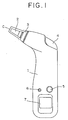
- thermometer includes a body housing 1 enclosing a circuit and power source, a probe 2 enclosing an infrared sensor externally projecting from the housing for a forward-and-backward movement, a release pipe 3 engaged with probe 2 for a forward-and-backward movement, and a release button 4 for pushing out release pipe 3 toward probe, whereby a probe cover removable means is constructed by release pipe 3 and release button 4.
- a push button 5 for power source
- a push button 6 for illumination
- LCD display 7 On a rear wall of the housing there is provided a battery cover 8 for replacement of a battery as a power source.
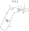
- probe 2 In use of the thermometer to be applied to a human body, probe 2 is so biased externally from housing 1 to slightly move backward toward release pipe 3 by inserting the same to an ear opening with certain force and to move forward to its original position by releasing the certain force.
- a start switch probe operation state detection switch, described later
- a start switch for switching in response to the forward-and-backward movement is so disposed within housing 1 that the start switch is turned to ON when probe 2 moves backward and turned to OFF when a measurement start signal is generated and probe 2 moves forward.
- thermometer is so designed that in out-of-use mode a cap 9 is mounted on probe 2 and in a measurement mode a probe cover C is mounted on probe 2 to be used for stain prevention and sanitary of probe 2.
- the probe cover C is adapted to be removed by release pipe 3.
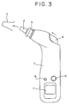
- release pipe 3 By pushing release button 4 in an arrow marked direction shown in Fig. 3, release pipe 3 projects from body housing 1 and cover C mounted on probe 2 is removed from probe 2.
- Release pipe 3 is locked in a projection state and returned to its original position by releasing the push applied to the release button 4.
- the pipe 3 has only to be pushed toward body housing 1 for returning to its original position to be locked there. Since pipe 3 in actual use moves backward when the probe cover C is mounted for measurement, intentional push is not required.
- the projection of release pipe 3 shows a state that probe cover C is not mounted on probe 2, and the withdrawal of the pipe shows a state of mounted. Accordingly, a cover switch within cover 1 (probe cover mount detection switch, described later) to be switched in response to the forward-and-backward movement of pipe 3 produces a signal representing whether or not cover C is mounted.
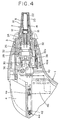
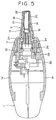
- body housing 1 consists of a front housing 1a and a ground housing 1b which are separably coupled one after other.
- Probe 2 consists of a wrapping member 10 and a probe body 12 removably mounted by wrapping member 10.
- a wave guide 14 for guiding infrared radiation extends from probe body 12, and an infrared radiation sensor (temperature detection sensor) 16 is disposed at a rear end of guide 14.
- a wave guide cap 20 is mounted on guide 14 through a ring 18, and at its tip is mounted by a protection filter 22. Infrared radiation passes through protection filter 22 and is guided by wave guide 14 to reach infrared radiation sensor 16.
- a lead frame of infrared radiation sensor 16 is pierced thorough sleeve 24 biassed toward wave guide 14 by a spring coil 26 engaged with a rear end of the sleeve, whereby infrared radiation sensor 16 disposed at a front end of sleeve 24 is pushed to a rear end of guide 14 to be held thereby and whole probe 2 is biassed outside housing 1.
- Spring coil 26 is also engaged with a sensor cap 28 to be supported between sleeve 24 and cap 28.
- Sensor cap 28 is engaged with a rear end of probe body 12.
- Probe switch 30 is disposed behind sensor cap 28 to be actuated thereby.
- probe 2 For a closing operation of start switch 30, probe 2 is depressed against spring coil 26 to move backward by a gap of spring coil 26 for moving sensor cap 28 backward. For an opening operation, the force pushing probe 2 is released to return probe 2 to its original position by coil 26, disengaging cap 28 from switch 30.
- Start switch 30 is fixed by a tap tight 36 to a probe base 32 mounted on front housing 1a.
- Probe base 32 is engaged with base cover 34 to produce a chamber inserted by base end of probe 2.
- Release pipe 3 engaged with probe 2 (viz. probe base 32 and base cover 34) for a forward-and-backward movement is engaged with a blade spring 38 bending toward probe base 32.
- Cover switch (probe cover mount detection switch) 40 having a lever 40a moving in response to forward-and-backward movement of release pipe 3 is mounted on probe base 32.
- blade spring 38 In withdrawal state of pipe 3 (probe cover is mounted), blade spring 38 is behind projection 32a formed on base 32 to be locked and lever 40a of cover switch 40 at a rear end of pipe 3 is positioned in a solid line (Fig. 4). In this state (switch 40 is turned to ON), switch 40 generates probe cover mount signal.
- Release button 4 for pushing release pipe 3 forward is mounted on body housing 1 for a slidable movement.
- button 4 is pushed against force by spring 42, a tip of button 4 comes into contact with a rear end of release pipe 3 to push the same forward to be locked in a projecting state as described above. If such push is released, button 4 is returned to its original position by spring 42.
- a flexible base 46 is wired to electrically connect infrared radiation sensor 16, start switch 30 and cover switch 40 with a circuit board (not shown in drawings), Electronic components are mounted on the circuit board in a predetermined pattern for measurement by thermometer and the board is fixed in front housing 1a of housing 1.
- the above-mentioned radiation clinical thermometer is characterized by that any measurement is not initiated even if a body temperature measurement start signal is generated when unmount signal of probe cover is produced by cover switch 40.
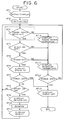
- This control is executed by circuits, and its operation will be explained hereinafter according to a flow chart shown in Fig. 6.
- step 1 Upon depression of power switch button 5 for power-on, predetermined information is displayed on LCD display 7 of body housing 1 as an initial display in a step 1 (briefly expressed as "ST1" hereinafter), and various values are initialized (ST2).
- ST3 it is inquired if probe cover is mounted. As described above this inquiry is performed based on a signal representing whether a cover mount signal is generated when release pipe 3 is withdrawn or a cover unmount signal is generated when it projects.
- cover unmount signal NO response
- a state of unmounted probe cover is displayed (ST12) and incompletion of measurement preparation is displayed (ST13). If the power supply is turned to be OFF for stopping measurement (ST14), a state of power-off is displayed (ST15) to finish the measurement. If the power supply is ON in ST14, the sequence returns to ST3.
- start switch 30 is OFF (ST4). If it is ON (NO response), measurement preparation is not completed and the sequence moves to ST13. YES response from ST4 is applied to ST5 to inquire if measurement preparation is completed. Unless completed, the sequence moves to ST13. If completed, completion of measurement preparation is displayed (ST6). After the display of completion, it is inquired if power supply is OFF (ST7). If OFF, the sequence moves to ST15. If in power-on state probe 2 moves backward by depression and start switch 30 becomes ON (ST8), body temperature measurement is initiated and a state of measuring is displayed (ST9). Then, for several seconds, measurement is executed (ST10), a measurement result (body temperature value) is displayed upon completion of the measurement (ST11), and the sequence returns to ST3. Even if start switch 30 is OFF in ST8, it returns to ST3.
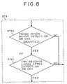
- Fig. 7 there is shown a flow chart when the above mentioned control further includes a counting means for delaying a measurement initiation for a predetermined time is employed after prohibition of measurement initiation by unmount signal of probe cover is released, viz., after the mount signal of probe cover is generated.
- the flow chart is fundamentally same as that of Fig. 6 except ST3 and ST4 shwon in Figs. 8 and 9.
- start switch (probe operation state detection switch) 30 when start switch (probe operation state detection switch) 30 is OFF (probe 2 is not depressed) in ST22, it is inquired if a predetermined time (herein, 4 seconds) has elapsed after start switch 30 turns to OFF (ST22). If YES response is produced, it moves to ST5. If NO response is produced in ST22 and ST23, it moves to ST13 where incompletion of measurement preparation is displayed.
- a predetermined time herein, 4 seconds
- counting is executed for several seconds just after probe cover is mounted or just after probe 2 is once depressed to return to its original state, measurement is prohibited until measurement preparation is completed.
- the radiation clinical thermometer unnecessary measurement which is generally apt to happen on mounting probe cover on probe is prevented. Though erroneous measurement is conventionally executed when measurement is executed in unmount state of probe cover, such erroneous measurement can be avoided in this thermometer because measurement is prohibited in unmount state. Moreover, the radiation clinical thermometer having counting means prevents unnecessary measurement by chattering on mounting probe cover, so that rough treatment does not invite unnecessary measurement.
Applications Claiming Priority (2)
| Application Number | Priority Date | Filing Date | Title |
|---|---|---|---|
| JP86738/92 | 1992-04-08 | ||
| JP08673892A JP3336359B2 (ja) | 1992-04-08 | 1992-04-08 | 放射式体温計 |
Publications (2)
| Publication Number | Publication Date |
|---|---|
| EP0565123A1 true EP0565123A1 (fr) | 1993-10-13 |
| EP0565123B1 EP0565123B1 (fr) | 1996-07-03 |
Family
ID=13895159
Family Applications (1)
| Application Number | Title | Priority Date | Filing Date |
|---|---|---|---|
| EP93105884A Expired - Lifetime EP0565123B1 (fr) | 1992-04-08 | 1993-04-08 | Thermomètre médical à radiations |
Country Status (3)
| Country | Link |
|---|---|
| EP (1) | EP0565123B1 (fr) |
| JP (1) | JP3336359B2 (fr) |
| DE (1) | DE69303410T2 (fr) |
Cited By (8)
| Publication number | Priority date | Publication date | Assignee | Title |
|---|---|---|---|---|
| DE19543096A1 (de) * | 1995-11-18 | 1997-05-22 | Braun Ag | Infrarot-Strahlungsthermometer |
| WO1997019331A1 (fr) * | 1995-11-18 | 1997-05-29 | Braun Aktiengesellschaft | Procede d'evaluation du signal emis par un thermometre a infrarouge et thermometre a infrarouge approprie |
| DE19600334A1 (de) * | 1996-01-08 | 1997-07-17 | Braun Ag | Verfahren zur Auswertung des Signales eines Infrarot-Thermometers, Vorrichtung zur Durchführung des Verfahrens sowie Meßkopf zur Verwendung in einem Infrarot-Thermometer |
| WO1998019143A1 (fr) * | 1996-10-25 | 1998-05-07 | Exergen Corporation | Thermometre axillaire a infrarouges et methode d'utilisation |
| DE19724054A1 (de) * | 1997-06-07 | 1998-12-10 | Braun Ag | Strahlungsthermometer und Schutzkappe dafür |
| US6367973B2 (en) * | 1998-09-29 | 2002-04-09 | Terumo Kabushiki Kaisha | Probe cover detaching mechanism and ear type clinical thermometer |
| US6394648B1 (en) * | 2000-11-22 | 2002-05-28 | K-Jump Health Co., Ltd. | Electronic thermometer |
| US6612735B2 (en) * | 2001-06-01 | 2003-09-02 | Omron Corporation | Infrared ray clinical thermometer |
Families Citing this family (4)
| Publication number | Priority date | Publication date | Assignee | Title |
|---|---|---|---|---|
| US6319206B1 (en) | 1999-11-24 | 2001-11-20 | Exergen Corporation | Temporal thermometer disposable cap |
| KR101004651B1 (ko) * | 2008-10-24 | 2011-01-04 | 주식회사 이노칩테크놀로지 | 귓속형 적외선 체온계 |
| JP2011062368A (ja) * | 2009-09-17 | 2011-03-31 | Terumo Corp | 耳式体温計 |
| KR102500772B1 (ko) * | 2020-10-20 | 2023-02-16 | 대양전기(주) | 전기 마사지 기능을 갖는 비접촉식 체온계 |
Citations (4)
| Publication number | Priority date | Publication date | Assignee | Title |
|---|---|---|---|---|
| US4993424A (en) * | 1989-12-04 | 1991-02-19 | Diatek, Incorporated | Infrared medical thermometer |
| US5046482A (en) * | 1988-03-31 | 1991-09-10 | Ivac Corporation | Disposable infrared thermometer insertion probe |
| EP0445784A2 (fr) * | 1990-03-08 | 1991-09-11 | Ivac Corporation | Appareil de protection pour une sonde biomédicale |
| WO1992011800A1 (fr) * | 1990-12-29 | 1992-07-23 | Omron Corporation | Thermometre clinique detecteur de rayonnements |
-
1992
- 1992-04-08 JP JP08673892A patent/JP3336359B2/ja not_active Expired - Lifetime
-
1993
- 1993-04-08 DE DE69303410T patent/DE69303410T2/de not_active Expired - Lifetime
- 1993-04-08 EP EP93105884A patent/EP0565123B1/fr not_active Expired - Lifetime
Patent Citations (4)
| Publication number | Priority date | Publication date | Assignee | Title |
|---|---|---|---|---|
| US5046482A (en) * | 1988-03-31 | 1991-09-10 | Ivac Corporation | Disposable infrared thermometer insertion probe |
| US4993424A (en) * | 1989-12-04 | 1991-02-19 | Diatek, Incorporated | Infrared medical thermometer |
| EP0445784A2 (fr) * | 1990-03-08 | 1991-09-11 | Ivac Corporation | Appareil de protection pour une sonde biomédicale |
| WO1992011800A1 (fr) * | 1990-12-29 | 1992-07-23 | Omron Corporation | Thermometre clinique detecteur de rayonnements |
Cited By (17)
| Publication number | Priority date | Publication date | Assignee | Title |
|---|---|---|---|---|
| WO1997019331A1 (fr) * | 1995-11-18 | 1997-05-29 | Braun Aktiengesellschaft | Procede d'evaluation du signal emis par un thermometre a infrarouge et thermometre a infrarouge approprie |
| WO1997019332A1 (fr) * | 1995-11-18 | 1997-05-29 | Braun Aktiengesellschaft | Thermometre a rayonnement infrarouge |
| DE19543096C2 (de) * | 1995-11-18 | 1998-07-23 | Braun Ag | Infrarot-Strahlungsthermometer |
| DE19543096A1 (de) * | 1995-11-18 | 1997-05-22 | Braun Ag | Infrarot-Strahlungsthermometer |
| US6149297A (en) * | 1995-11-18 | 2000-11-21 | Braun Gmbh | Infrared radiation thermometer |
| US6195581B1 (en) | 1995-11-18 | 2001-02-27 | Braun Gmbh | Process for evaluating the signal of an infrared thermometer, and infrared thermometer |
| DE19600334A1 (de) * | 1996-01-08 | 1997-07-17 | Braun Ag | Verfahren zur Auswertung des Signales eines Infrarot-Thermometers, Vorrichtung zur Durchführung des Verfahrens sowie Meßkopf zur Verwendung in einem Infrarot-Thermometer |
| DE19600334C2 (de) * | 1996-01-08 | 2002-11-14 | Braun Gmbh | Verfahren zur Auswertung des von einem Infrarotsensor eines Infrarot-Thermometers gelieferten Meßsignals sowie Infrarot-Thermometer |
| US6402371B2 (en) | 1996-10-25 | 2002-06-11 | Exergen Corporation | Axillary infrared thermometer and method of use |
| WO1998019143A1 (fr) * | 1996-10-25 | 1998-05-07 | Exergen Corporation | Thermometre axillaire a infrarouges et methode d'utilisation |
| US5874736A (en) * | 1996-10-25 | 1999-02-23 | Exergen Corporation | Axillary infrared thermometer and method of use |
| US6097979A (en) * | 1997-06-07 | 2000-08-01 | Braun Gmbh | Radiation thermometer and protective cover therefor |
| DE19724054C2 (de) * | 1997-06-07 | 2002-09-12 | Braun Gmbh | Strahlungsthermometer und Schutzkappe dafür |
| DE19724054A1 (de) * | 1997-06-07 | 1998-12-10 | Braun Ag | Strahlungsthermometer und Schutzkappe dafür |
| US6367973B2 (en) * | 1998-09-29 | 2002-04-09 | Terumo Kabushiki Kaisha | Probe cover detaching mechanism and ear type clinical thermometer |
| US6394648B1 (en) * | 2000-11-22 | 2002-05-28 | K-Jump Health Co., Ltd. | Electronic thermometer |
| US6612735B2 (en) * | 2001-06-01 | 2003-09-02 | Omron Corporation | Infrared ray clinical thermometer |
Also Published As
| Publication number | Publication date |
|---|---|
| JP3336359B2 (ja) | 2002-10-21 |
| DE69303410T2 (de) | 1997-03-06 |
| EP0565123B1 (fr) | 1996-07-03 |
| JPH05288609A (ja) | 1993-11-02 |
| DE69303410D1 (de) | 1996-08-08 |
Similar Documents
| Publication | Publication Date | Title |
|---|---|---|
| US5487607A (en) | Radiation clinical thermometer | |
| EP0565123B1 (fr) | Thermomètre médical à radiations | |
| JP3052379B2 (ja) | 耳式放射体温計 | |
| US7021824B2 (en) | Switch assembly for thermometry apparatus | |
| US6149297A (en) | Infrared radiation thermometer | |
| US5991652A (en) | Protective two position shell for an infrared thermometer | |
| US6195581B1 (en) | Process for evaluating the signal of an infrared thermometer, and infrared thermometer | |
| EP1262753B1 (fr) | Thermomètre clinique à infrarouge | |
| US4784149A (en) | Infrared thermometer with automatic calibration | |
| US7965335B2 (en) | Wireless camera flash trigger device | |
| US4502487A (en) | Optical thermodetector | |
| US4811198A (en) | Electronic thermometer having means for predicting a converged temperature | |
| US3905232A (en) | Electronic thermometer | |
| BR9503620A (pt) | Dispositivo de fixaçao | |
| MXPA04007703A (es) | Dispositivo para la medicion de la longitud y de la profundidad, de uso quirurgico. | |
| JP2632125B2 (ja) | 放射体温計 | |
| JP2513637Y2 (ja) | 放射体温計 | |
| EP0958779A4 (fr) | Thermometre de mesure de rayonnement | |
| KR200255560Y1 (ko) | 적외선 귀 체온계 | |
| JPS6124900Y2 (fr) | ||
| JP3455922B2 (ja) | 放射体温計 | |
| EP4105621A3 (fr) | Thermomètre à infrarouges | |
| GB2075206A (en) | Photographic camera | |
| JPS6133497B2 (fr) | ||
| JPH04324412A (ja) | 内視鏡装置 |
Legal Events
| Date | Code | Title | Description |
|---|---|---|---|
| PUAI | Public reference made under article 153(3) epc to a published international application that has entered the european phase |
Free format text: ORIGINAL CODE: 0009012 |
|
| 17P | Request for examination filed |
Effective date: 19930506 |
|
| AK | Designated contracting states |
Kind code of ref document: A1 Designated state(s): DE FR GB IT |
|
| 17Q | First examination report despatched |
Effective date: 19950811 |
|
| GRAH | Despatch of communication of intention to grant a patent |
Free format text: ORIGINAL CODE: EPIDOS IGRA |
|
| GRAA | (expected) grant |
Free format text: ORIGINAL CODE: 0009210 |
|
| AK | Designated contracting states |
Kind code of ref document: B1 Designated state(s): DE FR GB IT |
|
| ITF | It: translation for a ep patent filed |
Owner name: STUDIO TORTA SOCIETA' SEMPLICE |
|
| REF | Corresponds to: |
Ref document number: 69303410 Country of ref document: DE Date of ref document: 19960808 |
|
| ET | Fr: translation filed | ||
| PLBE | No opposition filed within time limit |
Free format text: ORIGINAL CODE: 0009261 |
|
| STAA | Information on the status of an ep patent application or granted ep patent |
Free format text: STATUS: NO OPPOSITION FILED WITHIN TIME LIMIT |
|
| 26N | No opposition filed | ||
| REG | Reference to a national code |
Ref country code: GB Ref legal event code: IF02 |
|
| REG | Reference to a national code |
Ref country code: FR Ref legal event code: TP |
|
| REG | Reference to a national code |
Ref country code: GB Ref legal event code: 732E |
|
| PG25 | Lapsed in a contracting state [announced via postgrant information from national office to epo] |
Ref country code: IT Free format text: LAPSE BECAUSE OF NON-PAYMENT OF DUE FEES Effective date: 20050408 |
|
| PGFP | Annual fee paid to national office [announced via postgrant information from national office to epo] |
Ref country code: FR Payment date: 20080414 Year of fee payment: 16 |
|
| PGFP | Annual fee paid to national office [announced via postgrant information from national office to epo] |
Ref country code: GB Payment date: 20080414 Year of fee payment: 16 |
|
| GBPC | Gb: european patent ceased through non-payment of renewal fee |
Effective date: 20090408 |
|
| REG | Reference to a national code |
Ref country code: FR Ref legal event code: ST Effective date: 20091231 |
|
| PG25 | Lapsed in a contracting state [announced via postgrant information from national office to epo] |
Ref country code: GB Free format text: LAPSE BECAUSE OF NON-PAYMENT OF DUE FEES Effective date: 20090408 Ref country code: FR Free format text: LAPSE BECAUSE OF NON-PAYMENT OF DUE FEES Effective date: 20091222 |
|
| PGFP | Annual fee paid to national office [announced via postgrant information from national office to epo] |
Ref country code: IT Payment date: 20080422 Year of fee payment: 16 |
|
| PGRI | Patent reinstated in contracting state [announced from national office to epo] |
Ref country code: IT Effective date: 20091201 |
|
| PGFP | Annual fee paid to national office [announced via postgrant information from national office to epo] |
Ref country code: DE Payment date: 20100430 Year of fee payment: 18 |
|
| PGRI | Patent reinstated in contracting state [announced from national office to epo] |
Ref country code: IT Effective date: 20091201 |
|
| REG | Reference to a national code |
Ref country code: DE Ref legal event code: R119 Ref document number: 69303410 Country of ref document: DE |
|
| REG | Reference to a national code |
Ref country code: DE Ref legal event code: R119 Ref document number: 69303410 Country of ref document: DE |
|
| REG | Reference to a national code |
Ref country code: DE Ref legal event code: R082 Ref document number: 69303410 Country of ref document: DE Representative=s name: KILIAN KILIAN & PARTNER MBB PATENTANWAELTE, DE Ref country code: DE Ref legal event code: R082 Ref document number: 69303410 Country of ref document: DE Representative=s name: KILIAN KILIAN & PARTNER, DE |
|
| PG25 | Lapsed in a contracting state [announced via postgrant information from national office to epo] |
Ref country code: DE Free format text: LAPSE BECAUSE OF NON-PAYMENT OF DUE FEES Effective date: 20111031 |