EP0564741A1 - Method and apparatus for repairing a pipeline - Google Patents
Method and apparatus for repairing a pipeline Download PDFInfo
- Publication number
- EP0564741A1 EP0564741A1 EP92310823A EP92310823A EP0564741A1 EP 0564741 A1 EP0564741 A1 EP 0564741A1 EP 92310823 A EP92310823 A EP 92310823A EP 92310823 A EP92310823 A EP 92310823A EP 0564741 A1 EP0564741 A1 EP 0564741A1
- Authority
- EP
- European Patent Office
- Prior art keywords
- pipeline
- repairing
- tubular
- tubular member
- tubular structure
- Prior art date
- Legal status (The legal status is an assumption and is not a legal conclusion. Google has not performed a legal analysis and makes no representation as to the accuracy of the status listed.)
- Granted
Links
Images


Classifications
-
- F—MECHANICAL ENGINEERING; LIGHTING; HEATING; WEAPONS; BLASTING
- F16—ENGINEERING ELEMENTS AND UNITS; GENERAL MEASURES FOR PRODUCING AND MAINTAINING EFFECTIVE FUNCTIONING OF MACHINES OR INSTALLATIONS; THERMAL INSULATION IN GENERAL
- F16L—PIPES; JOINTS OR FITTINGS FOR PIPES; SUPPORTS FOR PIPES, CABLES OR PROTECTIVE TUBING; MEANS FOR THERMAL INSULATION IN GENERAL
- F16L55/00—Devices or appurtenances for use in, or in connection with, pipes or pipe systems
- F16L55/18—Appliances for use in repairing pipes
-
- F—MECHANICAL ENGINEERING; LIGHTING; HEATING; WEAPONS; BLASTING
- F16—ENGINEERING ELEMENTS AND UNITS; GENERAL MEASURES FOR PRODUCING AND MAINTAINING EFFECTIVE FUNCTIONING OF MACHINES OR INSTALLATIONS; THERMAL INSULATION IN GENERAL
- F16L—PIPES; JOINTS OR FITTINGS FOR PIPES; SUPPORTS FOR PIPES, CABLES OR PROTECTIVE TUBING; MEANS FOR THERMAL INSULATION IN GENERAL
- F16L55/00—Devices or appurtenances for use in, or in connection with, pipes or pipe systems
- F16L55/16—Devices for covering leaks in pipes or hoses, e.g. hose-menders
- F16L55/162—Devices for covering leaks in pipes or hoses, e.g. hose-menders from inside the pipe
- F16L55/163—Devices for covering leaks in pipes or hoses, e.g. hose-menders from inside the pipe a ring, a band or a sleeve being pressed against the inner surface of the pipe
Definitions
- This invention relates to a method, apparatus, and material for repairing mainly an underground pipeline, such as a sewer.
- Methods for repairing a sewer pipe have involved applying lengthy tubular sheet material formed from a thickened solution of a curable resin in which high-strength fibers are dispersed onto the inner surface of the pipe applying pressure to the inside of the tubular sheet expanding it to bring it into intimate contact with the inner surface of the pipeline, and supplying pressurized steam into the tubular sheetlike material to heat it to cure the resin. It is particularly effective if longitudinal edges of the material overlap circumferentially (see EP-A-454309).
- a rigid pipe formed in the pipeline to line it does not necessarily adhere closely to the inner surface of the pipeline, but there is a good likelihood that a clearance may be left between the outer surface of the pipe and the inner surface of the pipeline which will allow the passage of underground water entering the pipeline through its damaged part.
- the pipeline is lined along its whole length, the underground water which has entered the clearance is required to flow a very long distance before leaving it to enter the pipeline, and the amount of water entering the pipeline is, therefore, negligible. If the pipeline is only partly lined, however, the distances between its damaged part and the ends of the lining pipe are too short to prevent a large amount of underground water from entering the pipeline and flowing into sewage.
- Another problem is that there are not a few cases where the work for lining a pipeline has to be done in the presence of a large amount of underground water which has entered it through its damaged part. Therefore, it is very likely that water may hinder the curing reaction of the resin, or that the cooling action of water may delay the effective heating of the resin and its curing.
- a pipeline such as a sewer
- a method of repairing a pipeline which comprises inserting a roll of a sheet-like material including a thickened solution of an ultraviolet-curing resin in which high-strength fibers are dispersed, and having a pair of longitudinal edge portions slidably overlapping each other, into a damaged part of the pipeline, causing its overlapping portions to slide on each other to expand the tubular sheetlike material and bring it into intimate contact with the inner surface of the pipeline, and irradiating the tubular sheetlike material with ultraviolet light from an ultraviolet lamp within the pipeline to cure the resin.
- a method of repairing a pipeline which comprises inserting a roll of a sheet material including a thickened solution of a curable resin in which high-strength fibers are dispersed and having a pair of longitudinal edge portions slidably overlapping each other hand having sealing materials capable of swelling with water on the outer surface of the tubular sheetlike material at least adjacent to both ends thereof, into a damaged part of the pipeline, causing its overlapping portions to slide on each other to expand the tubular sheetlike material and bring it into intimate contact with the inner surface of the pipeline, with the sealing materials sandwiched between the outer surface of the tubular sheetlike material and the inner surface of the pipeline so that at least one sealing material is located on each longitudinal side of the damaged part of the pipeline and curing the resin.
- This invention also provides an apparatus which is used for carrying out the method according to the first aspect of this invention, and which comprises a tubular member transmitting ultraviolet light, supporting members attached to both ends of the tubular member for supporting it against the inner surface of a pipeline, while being movable along the pipeline, mounts for a repairing material which are provided around the both ends of the tubular member for mounting both ends of the repairing material fitted around the tubular member, pressurizing means for supplying a pressurized fluid into the space between the tubular member and the mounts and an ultraviolet lamp positioned within the tubular member.
- a cooling fan for supplying air into the tubular member to cool the ultraviolet lamp.
- This invention also provides a repairing material which may be employed in the apparatus as defined above for lining a pipeline by the method according to the first aspect of this invention, and which material comprises a flexible and inflatable tube transmitting ultraviolet light, the said tubular sheetlike material about the inflatable tube, the repairing material being enclosed in a bag opaque to ultraviolet light.
- the repairing material may further include annular sealing members fitted to the outer surface of the tubular sheetlike material adjacent to both ends thereof, the sealing members being of a material which swells by absorbing water, so that it may also be employed for carrying out the method according to the second aspect of this invention.
- Figure 1 shows an apparatus embodying this invention which includes supporting members 1 and 2, and a tubular member 3 formed from a material transmitting ultraviolet light, such as quartz glass, and connected between the supporting members 1 and 2.
- the supporting members 1 and 2 are connected to each other by connecting rods 4.
- Each of the supporting members 1 and 2 is provided with a plurality of pivotally-mounted legs 5 which are urged by spring means 6 outwardly toward an open position, and each leg 5 is provided with a roller 8 for contacting the inner surface of a pipeline 7.
- Each supporting member 1 or 2 is provided with an annular mount 10 for repairing material 9 which will hereinafter be described.
- the rear supporting member 1 is provided with a socket 12 for an ultraviolet lamp 11 positioned within the tubular member 3.
- the supporting member 1 has a through hole 13 in its portion to which the socket 12 is attached, and a fan 14 is installed behind the socket 12 for supplying air into the tubular member 3 through the hole 13 to cool the ultraviolet lamp 11.
- An air supply pipe 15 is employed as pressurizing means for supplying compressed air into the space between the tubular member 3 and the mount 10 for the repairing material, through the supporting member 1.
- a cable 16 is attached to the rear supporting member 1 by a connector 17, and holds the air supply pipe 15 and an electric wire for supplying electricity to the ultraviolet lamp 11 and the cooling fan 14, its other end being located outside the pipeline 7.
- the front supporting member 2 has a cover 18 for preventing water, etc. from entering the tubular member 3.
- the repairing material 9, which is tubular, is fitted about the tubular member 3 and has its opposite ends fastened to the mounts 10 on the supporting members 1 and 2, respectively, as shown in Figure 1.
- Figure 1 shows in its lower half the repairing material 9 as fitted in the apparatus, while its upper half shows the repairing material 9 expanded by compressed air supplied into the space between it and the tubular member 3, and brought into contact with the inner surface of the pipeline 7.
- the repairing material 9 is shown in detail in Figure 3. It comprises a flexible and inflatable tube 19 formed from a plastics material transmitting ultraviolet light.
- a sheetlike material 20 is rolled around the inflatable tube 19 and forms a tubular structure 21.
- the sheetlike material 20 is composed mainly of a sheet material 22 formed from a thickened solution of an ultraviolet-curing resin in which high-strength fibers are dispersed, and includes a thin meshed woven fabric 23 of glass fibers bonded to the outer surface of the sheet material 22 and forming an integral part thereof, as shown in Figure 3.
- This arrangement is, however, not intended to limit the scope of this invention.
- This invention does not preclude the use of a woven fabric of a synthetic fiber, such as polyester fiber, instead of the woven fabric 23 of glass fibers.
- the woven fabric 23 need not necessarily be provided on the outer surface of the sheet material 20, but can alternatively be located on the inner surface of the sheet material 20, or between its inner and outer surfaces.
- the sheetlike material 20 may consist solely of the sheet material 22, but as the sheet material is formed merely from a thickened resin solution containing fibers dispersed therein, it is so low in strength before curing that the tubular sheetlike material 21 is likely to be excessively partially stretched, or broken when it is diametrically expanded. Therefore, the sheetlike material 20 is preferably reinforced by the woven fabric 23.
- the sheetlike material 20 has a width which is somewhat larger than the inner peripheral length of the pipeline 7, and the tubular structure 21 formed by winding it about the inflatable tube 19 has a pair of longitudinal edge portions 20',20'' slidably overlapping each other.
- the inflatable tube 19 has a pair of ends projecting from the ends, respectively, of the tubular structure material 21.
- Annular sealing members 24 are fitted about the tubular structure 21 adjacent to its ends, respectively.
- the sealing members are formed from a material which swells and increases its volume drastically by absorbing water, and generates pressure if its deformation is restrained by an external force.
- An appropriate material can be selected from among a variety of commercially available rubbers having the property of swelling or expanding with water. It will normally be pre-cured; that is, not one intended to be cured by the action of the ultraviolet lamp.
- Examples of the known materials comprise crystalline diene rubbers and resins having a high water absorbency.
- Examples of the crystalline diene rubbers are the blends of chloroprene rubber and rubbers obtained by the random copolymerization of styrene and dienes, and examples of the resins having a high power of absorbing water include crosslinked polyacrylates, crosslinked salts of copolymers of isobutylene and maleic anhydride, and crosslinked salts of copolymers of polyvinyl alcohol and acrylic acid.
- Typical swelling times are in the order of 10 hours and the materials may have a swelling capacity of up to 500%.
- the repairing material 9 is enclosed in a bag 25 opaque to ultraviolet light, until it is used for lining work.
- a method for repairing a damaged part 26 of the pipeline 7 with the repairing material 9 employing the apparatus as hereinabove described, is as follows.
- the repairing material 9 is removed from the bag 25, and put on about the tubular member 3, and the opposite ends of the inflatable tube 19 are fitted about the mounts 10 on the supporting members 1 and 2, respectively, and fastened thereto in a gastight fashion.
- the tubular member 3 and the repairing material 9 define a gastight closed space therebetween.
- the apparatus is inserted into the pipeline 7 through one end thereof, and moved along the pipeline 7 by e.g. a cable pulling the apparatus toward the other end of the pipeline.
- the legs 5 are urged outwardly of the supporting members 1 and 2 and remain in contact with the inner surface of the pipeline 7 to hold the apparatus substantially in the center of cross-section of the pipeline 7, while allowing the apparatus to move along the pipeline 7, as the rollers 8 roll on its inner surface.
- a pressurized fluid such as compressed air
- a source of supply outside the pipeline 7 into the space 27 between the tubular member 3 and the repairing material 9 through the cable 16 and the air supply pipe 15.
- the resulting increase in internal pressure of the inflatable tube 19 inflates it, and thereby expands the tubular sheetlike material 21 wound about it, as the overlapping portions of the sheetlike material 20 slide on each other, while the sealing members 24 fitted about the tubular sheetlike material 21 are also diametrically expanded.
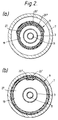
- the tubular sheetlike material 21 is brought into intimate contact with the inner surface of the pipeline 7, while the sealing members 24 are held between the outer surface of the tubular sheetlike material 21 and the inner surface of the pipeline 7 on the opposite side of the damaged part 26 from each other, as shown in the upper half of Figure 1 and Figure 2(b).
- the ultraviolet lamp 11 is supplied with an electric current to emit ultraviolet light for irradiating the sheetlike material 20 through the tubular member 3 and the inflatable tube 19 to cure the ultraviolet-curing resin in the sheet material 22.
- the fan 14 is placed in operation for supplying air into the tubular member 3 to cool the ultraviolet lamp 11 heated by the emission of ultraviolet light and thereby protect the inflatable tube 19 and the tubular sheetlike material 21 from being overheated.
- the damaged part of the pipeline 7 is, thus, repaired with the repairing material 9 which prevents the leakage of a fluid from the pipeline and of underground water thereinto.
- the damaged part 26 of the pipeline 7 forms a missing part of its wall, it is likely that the sheetlike material 20 may expand into the missing part to the extent that its overlapping portions form an opening therebetween. It is, therefore, desirable to place about the sheetlike material 20 in a tubular fabric or net which is not undesirably expanded by the internal pressure, but can hold the sheetlike material 20 against any undesirable expansion resulting in its overlapping portions forming an opening therebetween.
- the method according to the first aspect of this invention relies upon ultraviolet light for curing the sheetlike material 20, instead of heating it, and can, therefore, cure it rapidly. Moreover, it ensures the efficient curing of the ultraviolet-curing resin, even if underground water may enter the damaged part 26, since the resin employed does not have its curing reaction hindered by water.
- the method according to the second aspect of this invention employs the sealing members 24 interposed between the outer surface of the pipeline 7 adjacent to the opposite ends of the repairing material 9 held. In the event that underground water enters the clearance between the tubular structure 21 and the pipeline 7 through the damaged part 26, it is absorbed by the sealing members 24 and swells them.
- the swollen sealing members 24 have softened surfaces making intimate contact with the surfaces of the tubular structure 21 and the pipeline 7, and are restrained against deformation by the cured tubular structure 21 and the pipeline 7, resulting in the generation of pressure which forces the sealing members 24 against the tubular structure 21 and the pipeline 7.
- the swollen sealing members 24 form a seal between the tubular structure 21 and the pipeline 7 against any further leakage of underground water, and maintain their sealing actions without being collapsed by the pressure of underground water.
- the method according to the second aspect of this invention also enables the use of a thermosetting resin for forming the sheet material 22.
- a thermosetting resin for forming the sheet material 22.
- sealing member or members 24 covering the whole surface of the tubular structure 21.
- the sealing member or members 24 are interposed between the whole inner surface of the repaired part of the pipeline 7 and the whole outer surface of the tubular structure 21, and exhibits a sealing action by absorbing water along the whole length of the repairing material.
- This invention makes it possible to repair a damaged part of a long pipeline, such as a sewer pipe, without lining the pipeline along its whole length, and thereby shut off underground water effectively from entering the pipeline through its damaged part.
- the method according to the first aspect of this invention employs the ultraviolet-curing resin which is curable even in the presence of water, and the method according to the second aspect thereof employs the sealing members 24 which swell with water.
Landscapes
- Engineering & Computer Science (AREA)
- General Engineering & Computer Science (AREA)
- Mechanical Engineering (AREA)
- Pipe Accessories (AREA)
- Lining Or Joining Of Plastics Or The Like (AREA)
Abstract
Description
- This invention relates to a method, apparatus, and material for repairing mainly an underground pipeline, such as a sewer.
- When an underground pipeline has a damaged part or joint through which a fluid leaks out from the pipeline or underground water leaks into it, it is desirable to repair the damaged part or joint to prevent such leakage.
- When repairing such a pipeline, it has been usual to repair a long pipeline as a whole by inserting a tubular lining material into the pipeline and hardening the lining material along the inner surface of the pipeline.
- Methods for repairing a sewer pipe, for example, have involved applying lengthy tubular sheet material formed from a thickened solution of a curable resin in which high-strength fibers are dispersed onto the inner surface of the pipe applying pressure to the inside of the tubular sheet expanding it to bring it into intimate contact with the inner surface of the pipeline, and supplying pressurized steam into the tubular sheetlike material to heat it to cure the resin. It is particularly effective if longitudinal edges of the material overlap circumferentially (see EP-A-454309).
- If a long pipeline is only partly damaged, however, it is undesirable from an economical standpoint to line the whole pipeline and it is desirable to repair only its damaged part.
- The lining of only a part of a pipeline, such as a damaged part, however, presents different problems from those arising from the lining of the whole pipeline along its entire length.
- For example, when lining a sewer pipe by a method as described above, a rigid pipe formed in the pipeline to line it does not necessarily adhere closely to the inner surface of the pipeline, but there is a good likelihood that a clearance may be left between the outer surface of the pipe and the inner surface of the pipeline which will allow the passage of underground water entering the pipeline through its damaged part.
- If the pipeline is lined along its whole length, the underground water which has entered the clearance is required to flow a very long distance before leaving it to enter the pipeline, and the amount of water entering the pipeline is, therefore, negligible. If the pipeline is only partly lined, however, the distances between its damaged part and the ends of the lining pipe are too short to prevent a large amount of underground water from entering the pipeline and flowing into sewage.
- Another problem is that there are not a few cases where the work for lining a pipeline has to be done in the presence of a large amount of underground water which has entered it through its damaged part. Therefore, it is very likely that water may hinder the curing reaction of the resin, or that the cooling action of water may delay the effective heating of the resin and its curing.
- Under these circumstances, it is an object of this invention to enable the repairing of a pipeline, such as a sewer, which is limited to a damaged part thereof and, independently, to prevent underground water more effectively from entering the pipeline through its damaged part and past a comparatively short repair pipe.
- According to a first aspect of this invention, there is provided a method of repairing a pipeline which comprises inserting a roll of a sheet-like material including a thickened solution of an ultraviolet-curing resin in which high-strength fibers are dispersed, and having a pair of longitudinal edge portions slidably overlapping each other, into a damaged part of the pipeline, causing its overlapping portions to slide on each other to expand the tubular sheetlike material and bring it into intimate contact with the inner surface of the pipeline, and irradiating the tubular sheetlike material with ultraviolet light from an ultraviolet lamp within the pipeline to cure the resin.
- According to a second aspect of this invention, there is provided a method of repairing a pipeline which comprises inserting a roll of a sheet material including a thickened solution of a curable resin in which high-strength fibers are dispersed and having a pair of longitudinal edge portions slidably overlapping each other hand having sealing materials capable of swelling with water on the outer surface of the tubular sheetlike material at least adjacent to both ends thereof, into a damaged part of the pipeline, causing its overlapping portions to slide on each other to expand the tubular sheetlike material and bring it into intimate contact with the inner surface of the pipeline, with the sealing materials sandwiched between the outer surface of the tubular sheetlike material and the inner surface of the pipeline so that at least one sealing material is located on each longitudinal side of the damaged part of the pipeline and curing the resin.
- This invention also provides an apparatus which is used for carrying out the method according to the first aspect of this invention, and which comprises a tubular member transmitting ultraviolet light, supporting members attached to both ends of the tubular member for supporting it against the inner surface of a pipeline, while being movable along the pipeline, mounts for a repairing material which are provided around the both ends of the tubular member for mounting both ends of the repairing material fitted around the tubular member, pressurizing means for supplying a pressurized fluid into the space between the tubular member and the mounts and an ultraviolet lamp positioned within the tubular member. There is preferably also a cooling fan for supplying air into the tubular member to cool the ultraviolet lamp.
- This invention also provides a repairing material which may be employed in the apparatus as defined above for lining a pipeline by the method according to the first aspect of this invention, and which material comprises a flexible and inflatable tube transmitting ultraviolet light, the said tubular sheetlike material about the inflatable tube, the repairing material being enclosed in a bag opaque to ultraviolet light.
- The repairing material may further include annular sealing members fitted to the outer surface of the tubular sheetlike material adjacent to both ends thereof, the sealing members being of a material which swells by absorbing water, so that it may also be employed for carrying out the method according to the second aspect of this invention.
- Embodiments of the different aspects of the invention will now be described with reference to drawings wherein:
- Figure 1 is a diametrical sectional view of an apparatus embodying this invention with repair material shown in two different positions;
- Figure 2 are sectional views taken along the line II-II of Figure 1, and showing (a) the apparatus as positioned in a pipeline, and (b) an expanded repairing material, respectively; and
- Figure 3 is a perspective view of repairing material embodying this invention.
- Figure 1 shows an apparatus embodying this invention which includes supporting
members tubular member 3 formed from a material transmitting ultraviolet light, such as quartz glass, and connected between the supportingmembers members rods 4. - Each of the supporting
members legs 5 which are urged by spring means 6 outwardly toward an open position, and eachleg 5 is provided with aroller 8 for contacting the inner surface of apipeline 7. - Each supporting
member annular mount 10 for repairingmaterial 9 which will hereinafter be described. - The rear supporting
member 1 is provided with asocket 12 for anultraviolet lamp 11 positioned within thetubular member 3. - The supporting
member 1 has a throughhole 13 in its portion to which thesocket 12 is attached, and afan 14 is installed behind thesocket 12 for supplying air into thetubular member 3 through thehole 13 to cool theultraviolet lamp 11. - An
air supply pipe 15 is employed as pressurizing means for supplying compressed air into the space between thetubular member 3 and themount 10 for the repairing material, through the supportingmember 1. - A
cable 16 is attached to the rear supportingmember 1 by aconnector 17, and holds theair supply pipe 15 and an electric wire for supplying electricity to theultraviolet lamp 11 and thecooling fan 14, its other end being located outside thepipeline 7. - The front supporting
member 2 has acover 18 for preventing water, etc. from entering thetubular member 3. - The repairing
material 9, which is tubular, is fitted about thetubular member 3 and has its opposite ends fastened to themounts 10 on the supportingmembers material 9 as fitted in the apparatus, while its upper half shows the repairingmaterial 9 expanded by compressed air supplied into the space between it and thetubular member 3, and brought into contact with the inner surface of thepipeline 7. - The repairing
material 9 is shown in detail in Figure 3. It comprises a flexible andinflatable tube 19 formed from a plastics material transmitting ultraviolet light. - A
sheetlike material 20 is rolled around theinflatable tube 19 and forms atubular structure 21. Thesheetlike material 20 is composed mainly of asheet material 22 formed from a thickened solution of an ultraviolet-curing resin in which high-strength fibers are dispersed, and includes a thin meshedwoven fabric 23 of glass fibers bonded to the outer surface of thesheet material 22 and forming an integral part thereof, as shown in Figure 3. - This arrangement is, however, not intended to limit the scope of this invention. This invention does not preclude the use of a woven fabric of a synthetic fiber, such as polyester fiber, instead of the
woven fabric 23 of glass fibers. Moreover, thewoven fabric 23 need not necessarily be provided on the outer surface of thesheet material 20, but can alternatively be located on the inner surface of thesheet material 20, or between its inner and outer surfaces. - The
sheetlike material 20 may consist solely of thesheet material 22, but as the sheet material is formed merely from a thickened resin solution containing fibers dispersed therein, it is so low in strength before curing that the tubularsheetlike material 21 is likely to be excessively partially stretched, or broken when it is diametrically expanded. Therefore, thesheetlike material 20 is preferably reinforced by thewoven fabric 23. - The
sheetlike material 20 has a width which is somewhat larger than the inner peripheral length of thepipeline 7, and thetubular structure 21 formed by winding it about theinflatable tube 19 has a pair of longitudinal edge portions 20',20'' slidably overlapping each other. - The
inflatable tube 19 has a pair of ends projecting from the ends, respectively, of thetubular structure material 21. -
Annular sealing members 24 are fitted about thetubular structure 21 adjacent to its ends, respectively. - The sealing members are formed from a material which swells and increases its volume drastically by absorbing water, and generates pressure if its deformation is restrained by an external force. An appropriate material can be selected from among a variety of commercially available rubbers having the property of swelling or expanding with water. It will normally be pre-cured; that is, not one intended to be cured by the action of the ultraviolet lamp.
- Examples of the known materials comprise crystalline diene rubbers and resins having a high water absorbency. Examples of the crystalline diene rubbers are the blends of chloroprene rubber and rubbers obtained by the random copolymerization of styrene and dienes, and examples of the resins having a high power of absorbing water include crosslinked polyacrylates, crosslinked salts of copolymers of isobutylene and maleic anhydride, and crosslinked salts of copolymers of polyvinyl alcohol and acrylic acid. Typical swelling times are in the order of 10 hours and the materials may have a swelling capacity of up to 500%.
- The repairing
material 9 is enclosed in abag 25 opaque to ultraviolet light, until it is used for lining work. - A method for repairing a damaged
part 26 of thepipeline 7 with the repairingmaterial 9 employing the apparatus as hereinabove described, is as follows. - The repairing
material 9 is removed from thebag 25, and put on about thetubular member 3, and the opposite ends of theinflatable tube 19 are fitted about themounts 10 on the supportingmembers tubular member 3 and the repairingmaterial 9 define a gastight closed space therebetween. - It is alternatively possible within the scope of this invention to put the
inflatable tube 19 on about thetubular member 3, fit the opposite ends of theinflatable tube 19 about themounts 10 on the supportingmembers mounts 10 in a gastight fashion, and then wind thesheetlike material 20 about theinflatable tube 19. - Then, the apparatus is inserted into the
pipeline 7 through one end thereof, and moved along thepipeline 7 by e.g. a cable pulling the apparatus toward the other end of the pipeline. - The
legs 5 are urged outwardly of the supportingmembers pipeline 7 to hold the apparatus substantially in the center of cross-section of thepipeline 7, while allowing the apparatus to move along thepipeline 7, as therollers 8 roll on its inner surface. - When the apparatus has arrived at the damaged
part 26 of thepipeline 7, it is so positioned that the damagedpart 26 may be situated between the sealingmembers 24 on the repairingmaterial 9. This position is shown in the lower half of Figure 1 and Figure 2(a). - Then, a pressurized fluid, such as compressed air, is supplied from a source of supply outside the
pipeline 7 into thespace 27 between thetubular member 3 and the repairingmaterial 9 through thecable 16 and theair supply pipe 15. - The resulting increase in internal pressure of the
inflatable tube 19 inflates it, and thereby expands the tubularsheetlike material 21 wound about it, as the overlapping portions of thesheetlike material 20 slide on each other, while the sealingmembers 24 fitted about the tubularsheetlike material 21 are also diametrically expanded. - The tubular
sheetlike material 21 is brought into intimate contact with the inner surface of thepipeline 7, while thesealing members 24 are held between the outer surface of the tubularsheetlike material 21 and the inner surface of thepipeline 7 on the opposite side of the damagedpart 26 from each other, as shown in the upper half of Figure 1 and Figure 2(b). - The
ultraviolet lamp 11 is supplied with an electric current to emit ultraviolet light for irradiating thesheetlike material 20 through thetubular member 3 and theinflatable tube 19 to cure the ultraviolet-curing resin in thesheet material 22. - The
fan 14 is placed in operation for supplying air into thetubular member 3 to cool theultraviolet lamp 11 heated by the emission of ultraviolet light and thereby protect theinflatable tube 19 and the tubularsheetlike material 21 from being overheated. - When the tubular
sheetlike material 21 has been fully hardened, the supply of electric current to theultraviolet lamp 11 is discontinued, and a reduced pressure is created in thespace 27 to allow the detachment of theinflatable tube 19 from the inner surface of the hardened tubularsheetlike material 21 and the removal of the apparatus from thepipeline 7. - The damaged part of the
pipeline 7 is, thus, repaired with the repairingmaterial 9 which prevents the leakage of a fluid from the pipeline and of underground water thereinto. - If the damaged
part 26 of thepipeline 7 forms a missing part of its wall, it is likely that thesheetlike material 20 may expand into the missing part to the extent that its overlapping portions form an opening therebetween. It is, therefore, desirable to place about thesheetlike material 20 in a tubular fabric or net which is not undesirably expanded by the internal pressure, but can hold thesheetlike material 20 against any undesirable expansion resulting in its overlapping portions forming an opening therebetween. - The method according to the first aspect of this invention relies upon ultraviolet light for curing the
sheetlike material 20, instead of heating it, and can, therefore, cure it rapidly. Moreover, it ensures the efficient curing of the ultraviolet-curing resin, even if underground water may enter the damagedpart 26, since the resin employed does not have its curing reaction hindered by water. - There is known a method of lining the whole of a long pipeline which employs ultraviolet light for curing a resin as a lining material. This method, however, requires a very long time for a lining job, since it is necessary to move an ultraviolet lamp very slowly along the lining material held against the inner surface of the pipeline.
- It is, therefore, much lower in efficiency than a lining method which employs heating, e.g. steam heating for curing, as far as the lining of a long pipeline is concerned. If the pipeline is to be partly repaired, as contemplated by this invention, however, it is possible to accomplish its repair very quickly and efficiently, since it is sufficient to apply ultraviolet light to the lining material positioned near the part to be repaired.
- The method according to the second aspect of this invention employs the sealing
members 24 interposed between the outer surface of thepipeline 7 adjacent to the opposite ends of the repairingmaterial 9 held. In the event that underground water enters the clearance between thetubular structure 21 and thepipeline 7 through the damagedpart 26, it is absorbed by the sealingmembers 24 and swells them. - The
swollen sealing members 24 have softened surfaces making intimate contact with the surfaces of thetubular structure 21 and thepipeline 7, and are restrained against deformation by the curedtubular structure 21 and thepipeline 7, resulting in the generation of pressure which forces the sealingmembers 24 against thetubular structure 21 and thepipeline 7. - Thus, the
swollen sealing members 24 form a seal between thetubular structure 21 and thepipeline 7 against any further leakage of underground water, and maintain their sealing actions without being collapsed by the pressure of underground water. - The method according to the second aspect of this invention also enables the use of a thermosetting resin for forming the
sheet material 22. Although the water leaking in through the damagedpart 26 may hinder the curing of a thermosetting resin in the surface of the tubularsheetlike material 21, it is possible to achieve a satisfactory repairing job even if the surface of the tubular sheetlike material is not satisfactorily cured, since most of thetubular structure 21 is completely cured and has a sufficiently high strength, and theswollen sealing members 24 shut off water from entering the pipeline. - While it is necessary to fit the sealing
members 24 about thetubular structure 21 at least adjacent to the opposite ends thereof, it is possible to employ a sealing member ormembers 24 covering the whole surface of thetubular structure 21. The sealing member ormembers 24 are interposed between the whole inner surface of the repaired part of thepipeline 7 and the whole outer surface of thetubular structure 21, and exhibits a sealing action by absorbing water along the whole length of the repairing material. - It is preferable to combine the methods according to the first and second aspects of this invention by using an ultraviolet-curing resin for the
sheet material 22, and fitting the sealingmembers 24 about thetubular structure 21, as stated above in the description of the embodiments. - This invention makes it possible to repair a damaged part of a long pipeline, such as a sewer pipe, without lining the pipeline along its whole length, and thereby shut off underground water effectively from entering the pipeline through its damaged part.
- Even if underground water may be flowing into the pipeline through its damaged part during the work for repairing, it is possible to repair the damaged
part 26 and shut off underground water from flowing into the pipeline, since the method according to the first aspect of this invention employs the ultraviolet-curing resin which is curable even in the presence of water, and the method according to the second aspect thereof employs the sealingmembers 24 which swell with water.
Claims (7)
- A method of repairing a pipeline which comprises inserting a tubular structure (21) of a sheet material (20,22) including a thickened solution of an ultraviolet-curing resin in which high-strength fibers are dispersed and having a pair of longitudinal edge portions (20',20'') slidably overlapping each other into a damaged part (26) of said pipeline (7), causing said overlapping portions to slide on each other to expand said tubular structure (21) and bring it into intimate contact with the inner surface of said pipeline (7), and irradiating said tubular structure (21) with ultraviolet light from an ultraviolet lamp (11) positioned between the ends of the structure, to cure said resin.
- A method according to claim 1 which includes expanding an inner inflatable layer (19) of the structure (21) by fluid pressure to cause the said expansion of the structure (21), the irradiating being through the inflatable layer (19).
- A method of repairing a pipeline which comprises inserting a tubular structure (21) of a sheet material (20,22) including a thickened solution of a curable resin in which high-strength fibers are dispersed, having a pair of longitudinal edge portions (20',20'') slidably overlapping each other, and sealing materials (24) capable of swelling with water on the outer surface of said tubular structure material (21) at least adjacent to both ends thereof, into a damaged part (26) of said pipeline (7), causing said overlapping portions to slide on each other to expand said tubular structure (21) and bring it into intimate contact with the inner surface of said pipeline (7), while sandwiching said sealing materials (24) between the outer surface of said tubular structure (21) and the inner surface of said pipeline (7) so that at least one sealing material (24) may be located on each longitudinal side of said damaged part (26) of said pipeline (7), and curing said resin.
- An apparatus for repairing a pipeline which comprises a tubular member (3) capable of transmitting ultraviolet light, supporting members (1,2) attached to both ends of said tubular member (3) for supporting said tubular member (3) against the inner surface of a pipeline (7), while being movable along said pipeline, mounts (10) for a repairing material which are provided around the both ends of said tubular member (3) for mounting both ends of said repairing material (9) fitted around said tubular member (3), pressurizing means (15) for supplying a pressurized fluid into the space between said tubular member (3) and said mounts (10), and an ultraviolet lamp (11) positioned within said tubular member (3).
- Apparatus according to claim 4 which also includes a fan (14) for supplying air into said tubular member (3) to cool said ultraviolet lamp (11).
- A material for repairing a pipeline which comprises a flexible and inflatable tube (19) transmitting ultraviolet light, and a tubular structure (21) formed by a sheetlike material (20) wound about said inflatable tube (19) and having a pair of longitudinal edge portions (20',20'') slidably overlapping each other, said sheetlike material (20) being composed mainly of a sheet material (22) formed from a thickened solution of an ultraviolet-curing resin in which high-strength fibers are dispersed, said sheetlike material (20) having a width which is somewhat larger than the inner peripheral length of the pipeline (7) for which it is intended, said repairing material being enclosed in a bag (25) opaque to ultraviolet light.
- A material for repairing a pipeline according to claim 5, further including annular sealing materials (24) fitted to the outer surface of said tubular sheetlike material (21) at least adjacent to both ends thereof, said sealing materials being of a material which swells by absorbing water.
Applications Claiming Priority (2)
| Application Number | Priority Date | Filing Date | Title |
|---|---|---|---|
| JP115361/92 | 1992-04-07 | ||
| JP11536192 | 1992-04-07 |
Publications (2)
| Publication Number | Publication Date |
|---|---|
| EP0564741A1 true EP0564741A1 (en) | 1993-10-13 |
| EP0564741B1 EP0564741B1 (en) | 1998-11-04 |
Family
ID=14660627
Family Applications (1)
| Application Number | Title | Priority Date | Filing Date |
|---|---|---|---|
| EP92310823A Expired - Lifetime EP0564741B1 (en) | 1992-04-07 | 1992-11-26 | Method and apparatus for repairing a pipeline, and adapted repair material |
Country Status (6)
| Country | Link |
|---|---|
| US (1) | US5423630A (en) |
| EP (1) | EP0564741B1 (en) |
| JP (2) | JP2745184B2 (en) |
| CA (1) | CA2093458A1 (en) |
| DE (1) | DE69227505T2 (en) |
| DK (1) | DK0564741T3 (en) |
Cited By (19)
| Publication number | Priority date | Publication date | Assignee | Title |
|---|---|---|---|---|
| FR2716252A1 (en) * | 1994-02-16 | 1995-08-18 | Musthane Sarl | Underground pipe installation with tubular casing |
| WO1995029361A1 (en) * | 1994-04-26 | 1995-11-02 | Inc Bauchemie Ag | Process and device for renewing or repairing pipelines |
| EP0740102A2 (en) * | 1995-04-07 | 1996-10-30 | KÜBEL, Johann | Method and apparatus for renovating leaking pipe walls |
| DE19715616A1 (en) * | 1997-04-15 | 1999-01-21 | Bkp Berolina Polyester | Centering device for a relining curing device |
| EP0903530A1 (en) * | 1997-09-19 | 1999-03-24 | BKP Berolina Polyester GmbH & Co. KG | Hardenable hose element for pipe renovation |
| EP1065429A1 (en) * | 1999-06-29 | 2001-01-03 | Idroambiente s.a.s., di Giorgio Dini & C. | Production process of linings inside of shafts and /or conducts with water-resistant,resin coated felt |
| WO2005061945A1 (en) * | 2003-12-04 | 2005-07-07 | Blue Sky Forever, Inc. | Device and method for repairing pipe using hydrophilic seals |
| WO2007141554A1 (en) * | 2006-06-08 | 2007-12-13 | Halliburton Energy Services, Inc. | Apparatus for sealing and isolating pipelines |
| US7452161B2 (en) | 2006-06-08 | 2008-11-18 | Halliburton Energy Services, Inc. | Apparatus for sealing and isolating pipelines |
| EP1783417A3 (en) * | 2005-11-02 | 2009-11-18 | Copa Umweltservice GmbH | Method, sealing means and arrangement for the refurbishment of fluid conducting conduits |
| EP2123963A1 (en) * | 2008-05-19 | 2009-11-25 | KÜBEL, Johann | Method for sealing a tube section |
| US7975726B2 (en) | 2007-08-27 | 2011-07-12 | Lmk Enterprises, Inc. | Device and method for repairing pipe |
| ITMI20132061A1 (en) * | 2013-12-11 | 2015-06-12 | In Tec Srl | DEVICE AND PROCEDURE FOR REPAIRING A PORTION OF AT LEAST ONE TUBE |
| CN108019584A (en) * | 2016-11-04 | 2018-05-11 | 嵩鼎国际股份有限公司 | light curing lamp for pipeline |
| CN110260090A (en) * | 2019-07-08 | 2019-09-20 | 中北大学 | Novel pipeline plugging device and pipe leakage block isolation restorative procedure |
| WO2020011934A1 (en) * | 2018-07-13 | 2020-01-16 | I.S.T. Innovative Sewer Technologies Gmbh | Led uv system for pipe rehabilitation |
| US10683959B2 (en) | 2017-10-17 | 2020-06-16 | Lmk Technologies, Llc | Method and apparatus for repairing a length of pipe or a main/lateral pipe junction |
| US20210293367A1 (en) * | 2018-07-13 | 2021-09-23 | I.S.T. Innovative Sewer Technologies Gmbh | LED UV System for Pipe Rehabilitation |
| SE2150610A1 (en) * | 2021-05-12 | 2022-11-13 | Peanta Invent Ab | Pipe lining tool |
Families Citing this family (52)
| Publication number | Priority date | Publication date | Assignee | Title |
|---|---|---|---|---|
| DK0656504T3 (en) * | 1993-12-03 | 1999-05-03 | Uhrig Kanaltechnik Gmbh | Device for sealing leaks in pipes from the pipe interior and method for sealing leaks |
| US5628345A (en) * | 1994-06-22 | 1997-05-13 | American Pipeline Supply, Corp. | Point repair system for conduits |
| DE19608352C1 (en) * | 1996-03-05 | 1997-07-24 | Fitr Ges Fuer Innovation Im Ti | Repair line for heating and hot water pipelines |
| US5915419A (en) * | 1997-11-26 | 1999-06-29 | Insituform (Netherlands) B.V. | Cured in place lateral seal for relining of pipelines and method of manufacture |
| US6029726A (en) * | 1997-11-26 | 2000-02-29 | Insituform (Netherlands) B.V. | Apparatus for installing a flexible cured in place lateral seal in an existing main pipeline |
| US6068725A (en) * | 1997-11-26 | 2000-05-30 | Insituform (Netherlands) B.V. | Method of installation of a flexible cured in place lateral seal in an existing main pipeline |
| US6019136A (en) * | 1997-12-04 | 2000-02-01 | Fiberglass Coatings, Inc. | Conduit repair system |
| SE9803208D0 (en) * | 1998-09-21 | 1998-09-21 | Inpipe Sweden Ab | Fittings |
| JP2000220752A (en) * | 1999-02-03 | 2000-08-08 | Akashiya Kako Kk | Water-cut-off method using waterproof seal member |
| KR100379747B1 (en) * | 2000-07-22 | 2003-04-11 | 한국과학기술원 | Repairing Worn Drain-pipes by RTM Using Flexible Tube and Bagging Tube |
| US7228915B2 (en) * | 2001-01-26 | 2007-06-12 | E2Tech Limited | Device and method to seal boreholes |
| GB0131019D0 (en) * | 2001-12-27 | 2002-02-13 | Weatherford Lamb | Bore isolation |
| SE524743C2 (en) * | 2002-06-20 | 2004-09-21 | Sten Edstroem | Method and apparatus for sealing and / or renovating pipes |
| US8470226B2 (en) * | 2004-12-06 | 2013-06-25 | Medhesives, Inc. | Creating conduit end caps in the field |
| CN101111661A (en) * | 2005-01-31 | 2008-01-23 | 国际壳牌研究有限公司 | Method of installing an expandable tubular in a wellbore |
| JP2008533405A (en) * | 2005-03-16 | 2008-08-21 | ハンガンク カンパニー リミテッド | Non-excavation repair member and repair method for pipeline |
| US20060257559A1 (en) * | 2005-05-11 | 2006-11-16 | Warren Danny R | Method and system for insitu repair of interior water pipes |
| JP5025340B2 (en) * | 2007-06-14 | 2012-09-12 | 芦森工業株式会社 | Hose repair patch and hose repair method |
| US20100078118A1 (en) * | 2008-09-19 | 2010-04-01 | Ehsani Mohammad R | Repair and strengthening of small diameter pipes with frp laminates |
| CA2716219A1 (en) * | 2009-09-29 | 2011-03-29 | Press-Seal Gasket Corporation | Collapsible expansion mechanism for effecting a seal |
| US8720907B2 (en) | 2010-03-23 | 2014-05-13 | Press-Seal Gasket Corporation | Expansion ring assembly |
| US8821068B2 (en) * | 2010-07-12 | 2014-09-02 | Lmk Technologies, Llc | Manhole liner and method of using the same |
| US8752589B2 (en) * | 2010-12-02 | 2014-06-17 | Lmk Technologies, Llc | Method and apparatus for repairing the wall of a manhole |
| AU2012245500B2 (en) | 2011-04-18 | 2015-12-17 | Fyfe Co., Llc | Expandable liner for the protection and strengthening of existing pipes |
| US8783297B2 (en) * | 2011-04-27 | 2014-07-22 | Massachusetts Institute Of Technology | Robotic system for pipeline rehabilitation |
| DE102011103001B4 (en) * | 2011-05-24 | 2023-03-16 | Brandenburger Liner Gmbh & Co. Kg | Lining tube for the rehabilitation of defective sewers |
| JP5789166B2 (en) * | 2011-10-04 | 2015-10-07 | 株式会社スカイ・アーク | Concrete pipe inner wall cutting device |
| US9494271B2 (en) | 2012-01-11 | 2016-11-15 | Lmk Technologies, Llc | Pipe liner and method of using the same |
| JP6145304B2 (en) * | 2013-05-16 | 2017-06-07 | 吉佳エンジニアリング株式会社 | Light irradiation device and existing pipe repair method using the same |
| KR20170015926A (en) | 2014-06-16 | 2017-02-10 | 파이페 씨오. 엘엘씨 | Repair of pipes |
| WO2016009361A1 (en) | 2014-07-14 | 2016-01-21 | Fyfe Co. Llc | Method of reininforcing a pipe with a pipe lining, reinforced pipe and method of waterproofing a reinforced pipe |
| US9993992B2 (en) | 2015-04-17 | 2018-06-12 | Fyfe Co. Llc | Structural fabric useful for lining pipe |
| US10077855B2 (en) | 2015-09-22 | 2018-09-18 | Ina Acquisition Corp. | Method of lining pipe with high strength liner, high strength liner, and pipe lined with high strength liner |
| DE102015117206A1 (en) * | 2015-10-08 | 2017-04-13 | I.S.T. Innovative Sewer Technologies Gmbh | Curing device with a UV light-generating lamp |
| DE102016006561B4 (en) * | 2016-05-25 | 2022-07-28 | Uhrig Kanaltechnik Gmbh | Sealing sleeve for pipe offsets |
| US11118716B2 (en) | 2017-03-03 | 2021-09-14 | Ina Acquisition Corp. | Curing device for curing a pipe liner |
| US11173634B2 (en) | 2018-02-01 | 2021-11-16 | Ina Acquisition Corp | Electromagnetic radiation curable pipe liner and method of making and installing the same |
| JP6969746B2 (en) * | 2018-03-19 | 2021-11-24 | 富士電機株式会社 | Leakage repair method, light irradiation device used for leak repair |
| US10704728B2 (en) | 2018-03-20 | 2020-07-07 | Ina Acquisition Corp. | Pipe liner and method of making same |
| KR102036449B1 (en) * | 2018-04-27 | 2019-10-24 | 삼성엔지니어링 주식회사 | Automatic laminating apparatus and method for joining joints to pipes composed of fiber reinforced composite materials |
| KR102147216B1 (en) * | 2018-11-14 | 2020-08-25 | 한국로봇융합연구원 | Automatic laminating apparatus and method thereof for joining process of piping joints with adjustable size |
| DE102019111539A1 (en) * | 2019-05-03 | 2020-11-05 | Antje Krausser | Renovation packer with a guide |
| KR102082180B1 (en) * | 2019-05-15 | 2020-05-04 | 주식회사 힘센기술 | Partial repair apparatus using expansion tube of underground pipe and method for repairing pipe using this same |
| KR102082179B1 (en) * | 2019-05-24 | 2020-02-27 | 주식회사 힘센기술 | Air cooling uv lamp machine and method for repairing underground pipe using this same |
| US11585480B2 (en) * | 2019-07-23 | 2023-02-21 | General Electric Company | Systems and methods for maintaining pipes |
| AU2021244068A1 (en) * | 2020-03-23 | 2022-11-03 | Isealate As | Running tool for a downhole apparatus for patching a wall of a conduit and a method of patching a conduit |
| CN111750206A (en) * | 2020-06-17 | 2020-10-09 | 上海懿诚市政工程有限公司 | Ultraviolet light curing pipeline repairing method |
| CN111928058A (en) * | 2020-07-22 | 2020-11-13 | 上海锋泰建筑设备有限公司 | Be used for prosthetic headlight chain of urban underground pipeline ultraviolet curing |
| CN112359941B (en) * | 2020-10-11 | 2021-11-09 | 万维新材料科技(浙江)有限公司 | Integral ultraviolet curing repair process for sewage pipeline |
| US11873940B2 (en) * | 2020-11-04 | 2024-01-16 | Stephen A. Merlo | Cured in place pipe system having a sensor |
| KR102697756B1 (en) * | 2022-08-03 | 2024-08-23 | (주)신이앤씨 | Photocurable adhesive type pipeline repair packer |
| CN117053016A (en) * | 2023-10-12 | 2023-11-14 | 无棣海忠软管制造有限公司 | Pipeline lining repairing mechanism |
Citations (4)
| Publication number | Priority date | Publication date | Assignee | Title |
|---|---|---|---|---|
| GB1363380A (en) * | 1972-04-13 | 1974-08-14 | Wegner Co | Apparatus for internally sealing pipe sections |
| GB2172370A (en) * | 1985-03-14 | 1986-09-17 | British Gas Corp | Lining pipelines |
| DE4021456A1 (en) * | 1989-08-30 | 1991-03-07 | Hans Mueller | Renovation of localised damage in sewer pipes - in which resin impregnated mat is expanded against damaged wall and tapered resin rings are formed by inflation jacket at repair ends |
| US5042532A (en) * | 1989-08-01 | 1991-08-27 | Cues, Inc. | Expandable tube apparatus for repairing pipelines |
Family Cites Families (13)
| Publication number | Priority date | Publication date | Assignee | Title |
|---|---|---|---|---|
| SE435866B (en) * | 1983-04-06 | 1984-10-22 | Vj System Ab | PROCEDURE AND DEVICE FOR LINING OF PIPES, WITH A FLEXIBLE, HARDENABLE PLASTIC CONTAINING HOSE |
| JPS6118828U (en) * | 1984-07-06 | 1986-02-03 | 住友電気工業株式会社 | Tube for inner lining of steel pipes |
| JPS61143129A (en) * | 1984-12-18 | 1986-06-30 | 芦森工業株式会社 | Inner lining material for duct |
| JPH0643098B2 (en) * | 1985-07-22 | 1994-06-08 | インサイチユフオ−ム グル−プ リミテツド | Lining method for pipe system or passage |
| JPS63186744A (en) * | 1987-01-28 | 1988-08-02 | Showa Highpolymer Co Ltd | Photocurable fiber-reinforced plastic prepreg sheet |
| JPS63194929A (en) * | 1987-02-09 | 1988-08-12 | Osaka Bosui Constr Co Ltd | Leak-prevention process of buried sewer pipe |
| CH672536A5 (en) * | 1987-04-28 | 1989-11-30 | Ametex Ag | |
| JPH0829561B2 (en) * | 1988-09-12 | 1996-03-27 | 東京瓦斯株式会社 | Pipe liner |
| JPH02252529A (en) * | 1989-03-27 | 1990-10-11 | Tokyo Gas Co Ltd | Method for internal partial repair of pipeline |
| JPH0688363B2 (en) * | 1989-06-23 | 1994-11-09 | 日産車体株式会社 | Method for manufacturing hollow structure |
| JP2589191B2 (en) * | 1989-12-04 | 1997-03-12 | 東亜グラウト工業株式会社 | Waterproof coating |
| US5049003A (en) * | 1989-08-23 | 1991-09-17 | Kenneth Barton | Method and apparatus for repairing ruptures in underground conduits |
| JP2736368B2 (en) * | 1990-04-10 | 1998-04-02 | 芦森工業株式会社 | Pipe liner and pipe line lining method |
-
1992
- 1992-11-26 DE DE69227505T patent/DE69227505T2/en not_active Expired - Fee Related
- 1992-11-26 EP EP92310823A patent/EP0564741B1/en not_active Expired - Lifetime
- 1992-11-26 DK DK92310823T patent/DK0564741T3/en active
-
1993
- 1993-04-06 CA CA002093458A patent/CA2093458A1/en not_active Abandoned
- 1993-04-06 US US08/043,727 patent/US5423630A/en not_active Expired - Fee Related
- 1993-04-07 JP JP5106112A patent/JP2745184B2/en not_active Expired - Lifetime
- 1993-04-07 JP JP5106113A patent/JPH0615737A/en active Pending
Patent Citations (4)
| Publication number | Priority date | Publication date | Assignee | Title |
|---|---|---|---|---|
| GB1363380A (en) * | 1972-04-13 | 1974-08-14 | Wegner Co | Apparatus for internally sealing pipe sections |
| GB2172370A (en) * | 1985-03-14 | 1986-09-17 | British Gas Corp | Lining pipelines |
| US5042532A (en) * | 1989-08-01 | 1991-08-27 | Cues, Inc. | Expandable tube apparatus for repairing pipelines |
| DE4021456A1 (en) * | 1989-08-30 | 1991-03-07 | Hans Mueller | Renovation of localised damage in sewer pipes - in which resin impregnated mat is expanded against damaged wall and tapered resin rings are formed by inflation jacket at repair ends |
Non-Patent Citations (2)
| Title |
|---|
| DATABASE WPIL Section Ch, Week 8836, Derwent Publications Ltd., London, GB; Class A11, AN 88-254756 & JP-A-63 186 744 (SHOWA HIGH POLYMER KK.) * |
| PATENT ABSTRACTS OF JAPAN vol. 12, no. 471 9 December 1988 & JP-A-63 194 929 ( OSAKA BOSUI CONSTR. CO. LTD. ) * |
Cited By (34)
| Publication number | Priority date | Publication date | Assignee | Title |
|---|---|---|---|---|
| FR2716252A1 (en) * | 1994-02-16 | 1995-08-18 | Musthane Sarl | Underground pipe installation with tubular casing |
| WO1995029361A1 (en) * | 1994-04-26 | 1995-11-02 | Inc Bauchemie Ag | Process and device for renewing or repairing pipelines |
| EP0740102A2 (en) * | 1995-04-07 | 1996-10-30 | KÜBEL, Johann | Method and apparatus for renovating leaking pipe walls |
| AT402550B (en) * | 1995-04-07 | 1997-06-25 | Kuebel Johann | METHOD AND DEVICE FOR REFURBISHING THE LEAKING WALLS OF PIPES |
| EP0740102A3 (en) * | 1995-04-07 | 1997-06-25 | Johann Kubel | Method and apparatus for renovating leaking pipe walls |
| DE19715616A1 (en) * | 1997-04-15 | 1999-01-21 | Bkp Berolina Polyester | Centering device for a relining curing device |
| DE19715616C2 (en) * | 1997-04-15 | 1999-05-12 | Bkp Berolina Polyester | Centering device for a relining curing device |
| EP0903530A1 (en) * | 1997-09-19 | 1999-03-24 | BKP Berolina Polyester GmbH & Co. KG | Hardenable hose element for pipe renovation |
| EP1065429A1 (en) * | 1999-06-29 | 2001-01-03 | Idroambiente s.a.s., di Giorgio Dini & C. | Production process of linings inside of shafts and /or conducts with water-resistant,resin coated felt |
| WO2005061945A1 (en) * | 2003-12-04 | 2005-07-07 | Blue Sky Forever, Inc. | Device and method for repairing pipe using hydrophilic seals |
| US6994118B2 (en) | 2003-12-04 | 2006-02-07 | Blue Sky Forever, Inc. | Device and method for repairing pipe using hydrophilic seals |
| EP1783417A3 (en) * | 2005-11-02 | 2009-11-18 | Copa Umweltservice GmbH | Method, sealing means and arrangement for the refurbishment of fluid conducting conduits |
| AU2007255128B2 (en) * | 2006-06-08 | 2012-05-17 | Halliburton Energy Services, Inc. | Apparatus for sealing and isolating pipelines |
| WO2007141554A1 (en) * | 2006-06-08 | 2007-12-13 | Halliburton Energy Services, Inc. | Apparatus for sealing and isolating pipelines |
| US7452161B2 (en) | 2006-06-08 | 2008-11-18 | Halliburton Energy Services, Inc. | Apparatus for sealing and isolating pipelines |
| CN101466973B (en) * | 2006-06-08 | 2013-11-06 | 哈利伯顿能源服务公司 | Pipe tool and method for implementing maintenance operation in pipelines |
| US10458591B2 (en) | 2007-08-27 | 2019-10-29 | Lmk Technologies, Llc | Device and method for repairing pipe |
| US8667991B2 (en) | 2007-08-27 | 2014-03-11 | Lmk Technologies, Llc | Device and method for repairing pipe |
| US8667992B2 (en) | 2007-08-27 | 2014-03-11 | Lmk Technologies, Llc | Device and method for repairing pipe |
| US8678037B2 (en) | 2007-08-27 | 2014-03-25 | Lmk Technologies, Llc | Device and method for repairing pipe |
| US8689835B2 (en) | 2007-08-27 | 2014-04-08 | Lmk Technologies, Llc | Device and method for repairing pipe |
| US9366375B2 (en) | 2007-08-27 | 2016-06-14 | Lmk Technologies, Llc | Device and method for repairing pipe |
| US7975726B2 (en) | 2007-08-27 | 2011-07-12 | Lmk Enterprises, Inc. | Device and method for repairing pipe |
| EP3106731B1 (en) | 2007-08-27 | 2018-06-06 | LMK Technologies, LLC | Device and method for repairing pipe |
| EP2123963A1 (en) * | 2008-05-19 | 2009-11-25 | KÜBEL, Johann | Method for sealing a tube section |
| ITMI20132061A1 (en) * | 2013-12-11 | 2015-06-12 | In Tec Srl | DEVICE AND PROCEDURE FOR REPAIRING A PORTION OF AT LEAST ONE TUBE |
| WO2015087362A1 (en) * | 2013-12-11 | 2015-06-18 | In.Tec S.R.L. | A device and procedure for the repair of a portion of at least one pipe |
| CN108019584A (en) * | 2016-11-04 | 2018-05-11 | 嵩鼎国际股份有限公司 | light curing lamp for pipeline |
| US10683959B2 (en) | 2017-10-17 | 2020-06-16 | Lmk Technologies, Llc | Method and apparatus for repairing a length of pipe or a main/lateral pipe junction |
| WO2020011934A1 (en) * | 2018-07-13 | 2020-01-16 | I.S.T. Innovative Sewer Technologies Gmbh | Led uv system for pipe rehabilitation |
| US20210293367A1 (en) * | 2018-07-13 | 2021-09-23 | I.S.T. Innovative Sewer Technologies Gmbh | LED UV System for Pipe Rehabilitation |
| CN110260090A (en) * | 2019-07-08 | 2019-09-20 | 中北大学 | Novel pipeline plugging device and pipe leakage block isolation restorative procedure |
| SE2150610A1 (en) * | 2021-05-12 | 2022-11-13 | Peanta Invent Ab | Pipe lining tool |
| SE545096C2 (en) * | 2021-05-12 | 2023-03-28 | Peanta Invent Ab | Pipe lining tool |
Also Published As
| Publication number | Publication date |
|---|---|
| JPH0615737A (en) | 1994-01-25 |
| DK0564741T3 (en) | 1999-07-19 |
| DE69227505D1 (en) | 1998-12-10 |
| JP2745184B2 (en) | 1998-04-28 |
| CA2093458A1 (en) | 1993-10-08 |
| DE69227505T2 (en) | 1999-05-20 |
| US5423630A (en) | 1995-06-13 |
| JPH0615736A (en) | 1994-01-25 |
| EP0564741B1 (en) | 1998-11-04 |
Similar Documents
| Publication | Publication Date | Title |
|---|---|---|
| EP0564741B1 (en) | Method and apparatus for repairing a pipeline, and adapted repair material | |
| EP0241719B1 (en) | Improvements relating to lining of pipelines in passageways | |
| US5927341A (en) | Lining of "Tees" and "Wyes" in pipelines or passageways | |
| CA2805740C (en) | Bladderless pipeliner and method for using same | |
| US6029726A (en) | Apparatus for installing a flexible cured in place lateral seal in an existing main pipeline | |
| KR102082180B1 (en) | Partial repair apparatus using expansion tube of underground pipe and method for repairing pipe using this same | |
| KR100557753B1 (en) | Branch pipe liner bag and branch pipe lining method | |
| JPH05193003A (en) | Installation of tube liner and its device | |
| EP2208920B1 (en) | Method of sealing a pipeline and a sealing system | |
| JP2008539368A (en) | Pneumatic reversal insertion and steam curing apparatus and method for in-situ curing type liner | |
| JP2544839B2 (en) | Method of repairing a conduit and apparatus used for the method | |
| PL64136Y1 (en) | Installation of cured in place liner with inner impermeable layer and apparatus | |
| EP0870152B1 (en) | Method for lining underground pipelines | |
| JP3672629B2 (en) | Pipe branch repair device | |
| JPH0926081A (en) | Pipe branch part repairing device | |
| JP3691883B2 (en) | Repair method for existing pipelines | |
| JP4636752B2 (en) | Rehabilitation pipe water stop method and water stop member holding device | |
| JP3512434B2 (en) | Pipeline repair structure and method of forming the same | |
| JP3660400B2 (en) | Pipe branch repair method and repair device | |
| JP4318951B2 (en) | Repair material for mounting pipe, repair method and repair device using the same | |
| JP2678149B2 (en) | Branch pipe lining material and branch pipe lining method | |
| JPH07121552B2 (en) | Branch pipe lining method | |
| JPH05126294A (en) | Pipe mending work method | |
| JPH09123280A (en) | Repair work for branch pipe and sleeve for repair | |
| JP3178693B2 (en) | Partial lining method |
Legal Events
| Date | Code | Title | Description |
|---|---|---|---|
| PUAI | Public reference made under article 153(3) epc to a published international application that has entered the european phase |
Free format text: ORIGINAL CODE: 0009012 |
|
| AK | Designated contracting states |
Kind code of ref document: A1 Designated state(s): AT BE CH DE DK ES FR GB IE IT LI NL SE |
|
| RAP1 | Party data changed (applicant data changed or rights of an application transferred) |
Owner name: ASHIMORI INDUSTRY CO., LTD. |
|
| 17P | Request for examination filed |
Effective date: 19940405 |
|
| RAP1 | Party data changed (applicant data changed or rights of an application transferred) |
Owner name: ASHIMORI ENGINEERING CO., LTD Owner name: ASHIMORI INDUSTRY CO., LTD. |
|
| 17Q | First examination report despatched |
Effective date: 19951129 |
|
| GRAG | Despatch of communication of intention to grant |
Free format text: ORIGINAL CODE: EPIDOS AGRA |
|
| GRAG | Despatch of communication of intention to grant |
Free format text: ORIGINAL CODE: EPIDOS AGRA |
|
| GRAH | Despatch of communication of intention to grant a patent |
Free format text: ORIGINAL CODE: EPIDOS IGRA |
|
| GRAH | Despatch of communication of intention to grant a patent |
Free format text: ORIGINAL CODE: EPIDOS IGRA |
|
| RAP1 | Party data changed (applicant data changed or rights of an application transferred) |
Owner name: ASHIMORI ENGINEERING CO., LTD Owner name: ASHIMORI INDUSTRY CO., LTD. |
|
| RBV | Designated contracting states (corrected) |
Designated state(s): BE DE DK FR GB IE NL SE |
|
| GRAA | (expected) grant |
Free format text: ORIGINAL CODE: 0009210 |
|
| AK | Designated contracting states |
Kind code of ref document: B1 Designated state(s): BE DE DK FR GB IE NL SE |
|
| REF | Corresponds to: |
Ref document number: 69227505 Country of ref document: DE Date of ref document: 19981210 |
|
| REG | Reference to a national code |
Ref country code: IE Ref legal event code: FG4D |
|
| ET | Fr: translation filed | ||
| REG | Reference to a national code |
Ref country code: DK Ref legal event code: T3 |
|
| PLBE | No opposition filed within time limit |
Free format text: ORIGINAL CODE: 0009261 |
|
| STAA | Information on the status of an ep patent application or granted ep patent |
Free format text: STATUS: NO OPPOSITION FILED WITHIN TIME LIMIT |
|
| 26N | No opposition filed | ||
| PGFP | Annual fee paid to national office [announced via postgrant information from national office to epo] |
Ref country code: SE Payment date: 19991122 Year of fee payment: 8 |
|
| PGFP | Annual fee paid to national office [announced via postgrant information from national office to epo] |
Ref country code: NL Payment date: 19991124 Year of fee payment: 8 Ref country code: BE Payment date: 19991124 Year of fee payment: 8 |
|
| PGFP | Annual fee paid to national office [announced via postgrant information from national office to epo] |
Ref country code: DK Payment date: 19991129 Year of fee payment: 8 |
|
| PG25 | Lapsed in a contracting state [announced via postgrant information from national office to epo] |
Ref country code: DK Free format text: LAPSE BECAUSE OF NON-PAYMENT OF DUE FEES Effective date: 20001126 |
|
| PG25 | Lapsed in a contracting state [announced via postgrant information from national office to epo] |
Ref country code: SE Free format text: THE PATENT HAS BEEN ANNULLED BY A DECISION OF A NATIONAL AUTHORITY Effective date: 20001129 |
|
| PG25 | Lapsed in a contracting state [announced via postgrant information from national office to epo] |
Ref country code: BE Free format text: LAPSE BECAUSE OF NON-PAYMENT OF DUE FEES Effective date: 20001130 |
|
| BERE | Be: lapsed |
Owner name: ASHIMORI ENGINEERING CO. LTD Effective date: 20001130 Owner name: ASHIMORI INDUSTRY CO. LTD Effective date: 20001130 |
|
| PG25 | Lapsed in a contracting state [announced via postgrant information from national office to epo] |
Ref country code: NL Free format text: LAPSE BECAUSE OF NON-PAYMENT OF DUE FEES Effective date: 20010601 |
|
| EUG | Se: european patent has lapsed |
Ref document number: 92310823.7 |
|
| REG | Reference to a national code |
Ref country code: DK Ref legal event code: EBP |
|
| NLV4 | Nl: lapsed or anulled due to non-payment of the annual fee |
Effective date: 20010601 |
|
| PGFP | Annual fee paid to national office [announced via postgrant information from national office to epo] |
Ref country code: FR Payment date: 20011119 Year of fee payment: 10 |
|
| REG | Reference to a national code |
Ref country code: GB Ref legal event code: IF02 |
|
| REG | Reference to a national code |
Ref country code: GB Ref legal event code: 732E |
|
| PGFP | Annual fee paid to national office [announced via postgrant information from national office to epo] |
Ref country code: DE Payment date: 20021128 Year of fee payment: 11 |
|
| PG25 | Lapsed in a contracting state [announced via postgrant information from national office to epo] |
Ref country code: FR Free format text: LAPSE BECAUSE OF NON-PAYMENT OF DUE FEES Effective date: 20030731 |
|
| REG | Reference to a national code |
Ref country code: FR Ref legal event code: ST |
|
| PGFP | Annual fee paid to national office [announced via postgrant information from national office to epo] |
Ref country code: IE Payment date: 20031127 Year of fee payment: 12 |
|
| PG25 | Lapsed in a contracting state [announced via postgrant information from national office to epo] |
Ref country code: DE Free format text: LAPSE BECAUSE OF NON-PAYMENT OF DUE FEES Effective date: 20040602 |
|
| PG25 | Lapsed in a contracting state [announced via postgrant information from national office to epo] |
Ref country code: IE Free format text: LAPSE BECAUSE OF NON-PAYMENT OF DUE FEES Effective date: 20041126 |
|
| REG | Reference to a national code |
Ref country code: GB Ref legal event code: 732E |
|
| REG | Reference to a national code |
Ref country code: IE Ref legal event code: MM4A |
|
| PGFP | Annual fee paid to national office [announced via postgrant information from national office to epo] |
Ref country code: GB Payment date: 20081126 Year of fee payment: 17 |
|
| GBPC | Gb: european patent ceased through non-payment of renewal fee |
Effective date: 20091126 |
|
| PG25 | Lapsed in a contracting state [announced via postgrant information from national office to epo] |
Ref country code: GB Free format text: LAPSE BECAUSE OF NON-PAYMENT OF DUE FEES Effective date: 20091126 |