EP0564149A2 - Alimentation d'énergie avec condensateur de stockage - Google Patents
Alimentation d'énergie avec condensateur de stockage Download PDFInfo
- Publication number
- EP0564149A2 EP0564149A2 EP93302233A EP93302233A EP0564149A2 EP 0564149 A2 EP0564149 A2 EP 0564149A2 EP 93302233 A EP93302233 A EP 93302233A EP 93302233 A EP93302233 A EP 93302233A EP 0564149 A2 EP0564149 A2 EP 0564149A2
- Authority
- EP
- European Patent Office
- Prior art keywords
- capacitor
- power supply
- block
- charging
- voltage
- Prior art date
- Legal status (The legal status is an assumption and is not a legal conclusion. Google has not performed a legal analysis and makes no representation as to the accuracy of the status listed.)
- Granted
Links
Images


Classifications
-
- H—ELECTRICITY
- H02—GENERATION; CONVERSION OR DISTRIBUTION OF ELECTRIC POWER
- H02J—CIRCUIT ARRANGEMENTS OR SYSTEMS FOR SUPPLYING OR DISTRIBUTING ELECTRIC POWER; SYSTEMS FOR STORING ELECTRIC ENERGY
- H02J7/00—Circuit arrangements for charging or depolarising batteries or for supplying loads from batteries
- H02J7/34—Parallel operation in networks using both storage and other dc sources, e.g. providing buffering
- H02J7/345—Parallel operation in networks using both storage and other dc sources, e.g. providing buffering using capacitors as storage or buffering devices
-
- B—PERFORMING OPERATIONS; TRANSPORTING
- B60—VEHICLES IN GENERAL
- B60L—PROPULSION OF ELECTRICALLY-PROPELLED VEHICLES; SUPPLYING ELECTRIC POWER FOR AUXILIARY EQUIPMENT OF ELECTRICALLY-PROPELLED VEHICLES; ELECTRODYNAMIC BRAKE SYSTEMS FOR VEHICLES IN GENERAL; MAGNETIC SUSPENSION OR LEVITATION FOR VEHICLES; MONITORING OPERATING VARIABLES OF ELECTRICALLY-PROPELLED VEHICLES; ELECTRIC SAFETY DEVICES FOR ELECTRICALLY-PROPELLED VEHICLES
- B60L50/00—Electric propulsion with power supplied within the vehicle
- B60L50/40—Electric propulsion with power supplied within the vehicle using propulsion power supplied by capacitors
-
- B—PERFORMING OPERATIONS; TRANSPORTING
- B60—VEHICLES IN GENERAL
- B60L—PROPULSION OF ELECTRICALLY-PROPELLED VEHICLES; SUPPLYING ELECTRIC POWER FOR AUXILIARY EQUIPMENT OF ELECTRICALLY-PROPELLED VEHICLES; ELECTRODYNAMIC BRAKE SYSTEMS FOR VEHICLES IN GENERAL; MAGNETIC SUSPENSION OR LEVITATION FOR VEHICLES; MONITORING OPERATING VARIABLES OF ELECTRICALLY-PROPELLED VEHICLES; ELECTRIC SAFETY DEVICES FOR ELECTRICALLY-PROPELLED VEHICLES
- B60L53/00—Methods of charging batteries, specially adapted for electric vehicles; Charging stations or on-board charging equipment therefor; Exchange of energy storage elements in electric vehicles
- B60L53/50—Charging stations characterised by energy-storage or power-generation means
- B60L53/55—Capacitors
-
- B—PERFORMING OPERATIONS; TRANSPORTING
- B60—VEHICLES IN GENERAL
- B60L—PROPULSION OF ELECTRICALLY-PROPELLED VEHICLES; SUPPLYING ELECTRIC POWER FOR AUXILIARY EQUIPMENT OF ELECTRICALLY-PROPELLED VEHICLES; ELECTRODYNAMIC BRAKE SYSTEMS FOR VEHICLES IN GENERAL; MAGNETIC SUSPENSION OR LEVITATION FOR VEHICLES; MONITORING OPERATING VARIABLES OF ELECTRICALLY-PROPELLED VEHICLES; ELECTRIC SAFETY DEVICES FOR ELECTRICALLY-PROPELLED VEHICLES
- B60L58/00—Methods or circuit arrangements for monitoring or controlling batteries or fuel cells, specially adapted for electric vehicles
- B60L58/10—Methods or circuit arrangements for monitoring or controlling batteries or fuel cells, specially adapted for electric vehicles for monitoring or controlling batteries
-
- H—ELECTRICITY
- H02—GENERATION; CONVERSION OR DISTRIBUTION OF ELECTRIC POWER
- H02J—CIRCUIT ARRANGEMENTS OR SYSTEMS FOR SUPPLYING OR DISTRIBUTING ELECTRIC POWER; SYSTEMS FOR STORING ELECTRIC ENERGY
- H02J7/00—Circuit arrangements for charging or depolarising batteries or for supplying loads from batteries
- H02J7/0013—Circuit arrangements for charging or depolarising batteries or for supplying loads from batteries acting upon several batteries simultaneously or sequentially
- H02J7/0014—Circuits for equalisation of charge between batteries
- H02J7/0016—Circuits for equalisation of charge between batteries using shunting, discharge or bypass circuits
-
- Y—GENERAL TAGGING OF NEW TECHNOLOGICAL DEVELOPMENTS; GENERAL TAGGING OF CROSS-SECTIONAL TECHNOLOGIES SPANNING OVER SEVERAL SECTIONS OF THE IPC; TECHNICAL SUBJECTS COVERED BY FORMER USPC CROSS-REFERENCE ART COLLECTIONS [XRACs] AND DIGESTS
- Y02—TECHNOLOGIES OR APPLICATIONS FOR MITIGATION OR ADAPTATION AGAINST CLIMATE CHANGE
- Y02T—CLIMATE CHANGE MITIGATION TECHNOLOGIES RELATED TO TRANSPORTATION
- Y02T10/00—Road transport of goods or passengers
- Y02T10/60—Other road transportation technologies with climate change mitigation effect
- Y02T10/70—Energy storage systems for electromobility, e.g. batteries
-
- Y—GENERAL TAGGING OF NEW TECHNOLOGICAL DEVELOPMENTS; GENERAL TAGGING OF CROSS-SECTIONAL TECHNOLOGIES SPANNING OVER SEVERAL SECTIONS OF THE IPC; TECHNICAL SUBJECTS COVERED BY FORMER USPC CROSS-REFERENCE ART COLLECTIONS [XRACs] AND DIGESTS
- Y02—TECHNOLOGIES OR APPLICATIONS FOR MITIGATION OR ADAPTATION AGAINST CLIMATE CHANGE
- Y02T—CLIMATE CHANGE MITIGATION TECHNOLOGIES RELATED TO TRANSPORTATION
- Y02T10/00—Road transport of goods or passengers
- Y02T10/60—Other road transportation technologies with climate change mitigation effect
- Y02T10/7072—Electromobility specific charging systems or methods for batteries, ultracapacitors, supercapacitors or double-layer capacitors
-
- Y—GENERAL TAGGING OF NEW TECHNOLOGICAL DEVELOPMENTS; GENERAL TAGGING OF CROSS-SECTIONAL TECHNOLOGIES SPANNING OVER SEVERAL SECTIONS OF THE IPC; TECHNICAL SUBJECTS COVERED BY FORMER USPC CROSS-REFERENCE ART COLLECTIONS [XRACs] AND DIGESTS
- Y02—TECHNOLOGIES OR APPLICATIONS FOR MITIGATION OR ADAPTATION AGAINST CLIMATE CHANGE
- Y02T—CLIMATE CHANGE MITIGATION TECHNOLOGIES RELATED TO TRANSPORTATION
- Y02T90/00—Enabling technologies or technologies with a potential or indirect contribution to GHG emissions mitigation
- Y02T90/10—Technologies relating to charging of electric vehicles
- Y02T90/12—Electric charging stations
-
- Y—GENERAL TAGGING OF NEW TECHNOLOGICAL DEVELOPMENTS; GENERAL TAGGING OF CROSS-SECTIONAL TECHNOLOGIES SPANNING OVER SEVERAL SECTIONS OF THE IPC; TECHNICAL SUBJECTS COVERED BY FORMER USPC CROSS-REFERENCE ART COLLECTIONS [XRACs] AND DIGESTS
- Y02—TECHNOLOGIES OR APPLICATIONS FOR MITIGATION OR ADAPTATION AGAINST CLIMATE CHANGE
- Y02T—CLIMATE CHANGE MITIGATION TECHNOLOGIES RELATED TO TRANSPORTATION
- Y02T90/00—Enabling technologies or technologies with a potential or indirect contribution to GHG emissions mitigation
- Y02T90/10—Technologies relating to charging of electric vehicles
- Y02T90/14—Plug-in electric vehicles
Definitions
- the present invention relates to a storage capacitor power supply which stores electrical power in a capacitor block consisting of a plurality of electric double layer capacitors connected in series, in parallel or in any combination of series and parallel and supplies electrical power to a load.
- One promising type of electric vehicle is a vehicle which has no gearing as used in an automobile with an internal combustion engine but drives the four wheels independently, using wheel motors.
- the driving mechanism of this vehicle is simplified.
- the problems with the operating characteristics and the operability can be solved by coordinating and controlling the wheel motors.
- the greatest technical problem with the electric vehicle is to realize an ideal power source, i.e., a battery having a capacity comparable to an automotive engine.
- a battery is needed which is comparable in size and weight to an internal combustion engine and whose capacity can deliver power comparable to the power delivered by a gasoline engine.
- the battery must be recharged quickly or must be replaced with a fully charged battery as simply as supply of gasoline.
- the invention provides a storage capacitor power supply adapted to store electricity in a capacitor block consisting of a plurality of capacitors connected in series, in parallel or in any combination of series and parallel and to supply electric power to a load, said power supply comprising: the capacitor block connected with the load and supplying electric power directly to the load; a charging circuit for electrically charging the capacitor block; a charging power supply connected with the capacitor block via the charging circuit; and charge-limiting circuits which detect the voltages developed across the capacitors and limit charging of the capacitors if the detected voltages reach a given value.
- One embodiment of the invention further includes charging-limiting circuits and full charge-detecting circuits connected in parallel with their respective capacitors.
- the charge-limiting circuits cause the charging current to bypass the capacitors.
- the full charge-detecting circuits sense that the charge-limiting circuits are operated and make a decision to see that full charge is attained.
- the power supply further includes a residual electricity-detecting circuit.
- This residual electricity-detecting circuit consists of a multiplier circuit and an arithmetic circuit.
- the multiplier circuit takes the voltage developed across the capacitor and produces the square of the taken voltage.
- the arithmetic circuit multiplies the voltage by a constant factor.
- the residual electricity-detecting circuit takes the voltage developed across the terminals of the capacitor, applies the voltage to a series combination of a resistor, a voltage regulation element, and a detecting device, and detects a current according to the residual electricity by means of the detecting device.
- the invention further offers a storage capacitor power supply for supplying electric power to a load from charged capacitors, said power supply comprising: a first capacitor block connected with the load and supplying electric power directly to the load; a charging circuit for electrically charging the first capacitor block; a second capacitor block connected with the first capacitor block via the charging circuit and acting as a power supply for the first capacitor block; and a charging control circuit which detects the voltage developed across the terminals of the first capacitor block and controls the charging circuit in such a way that the first capacitor block is charged by the second capacitor block until the detected voltage reaches a given voltage.
- novel storage capacitor power supply comprises the capacitor block connected with the load and supplying electric power directly to the load, the charging circuit electrically charging the capacitor block, and the charging power supply connected with the capacitor block via the charging circuit.
- the voltage developed across the terminals of each capacitor is detected.
- the charge-limiting circuit senses that this voltage has reached a given value and limits charging of the capacitor. Therefore, the capacitor block can be used up to the intended maximum voltage. Hence, the efficiency at which the electrical energy is stored can be enhanced.
- a storage capacitor power supply according to one embodiment of the invention.
- This power supply comprises a charging power supply 1, a charging circuit 2, a voltage-detecting circuit 3, a capacitor C having a large capacitance, reference voltage sources producing reference voltages Vr and Vr', respectively, and switches S1 and S2.
- a load 4 is connected with this storage capacitor power supply.
- the capacitor C having a large capacitance is connected with the charging power supply 1 via the switch S1 and via the charging circuit 2.
- the capacitor C is also connected with the load 4.
- the capacitor C supplies electric power directly to the load 4.
- the charging power supply 1 which acts to electrically charge the capacitor C can be the commercial power line.
- the charging circuit 2 has a voltage converter means such as an inverter.
- the voltage-detecting circuit 3 compares the voltage developed across the terminals of the capacitor C with the reference voltages Vr and Vr' and senses whether the voltage across the terminals of the capacitor C is the fully charged level. If this level is reached, the voltage-detecting circuit 3 opens the switch S1 and closes the switch S2.
- the large-capacity capacitor C is electrically charged from the charging power supply 1 via the charging circuit 2 while the switch S1 is kept close until the voltage developed across the terminal of the capacitor C reaches the fully charged level.
- the switch S1 is opened to stop the charging. This prevents the voltage applied to the capacitor C from becoming excessively large compared with the rated voltage.
- the switch S2 is closed to short-circuit the some reference voltage Vr'. Thus, a dead band is established for the turning on and off of the switch S1.
- FIG. 2 there is shown another storage capacitor power supply according to the invention.
- This power supply is similar to the power supply already described in connection with Fig. 1 except that a series combination of a transistor TR and a resistor R2 is connected as a bypass circuit for the charging current flowing into the large-capacity capacitor C, and that the voltage produced across the terminals of the capacitor C is limited to a voltage set by a voltage regulation device ZD. Also shown is a resistor R1.
- the voltage set by the voltage regulation device ZD is selected to be equal to the voltage assumed when the capacitor C is fully charged. In this fully charged condition, the transistor TR conducts. The current flowing through the conducting transistor TR varies so as to maintain the voltage developed across the terminals of the capacitor C at the voltage corresponding to the fully charged condition. That is, a voltage limiter is formed.
- FIG. 3 there is shown a further storage battery power supply according to the invention.
- This power supply comprises a charging AC power supply 11, a charging DC power supply 12, charging circuits 13-15, a charging control circuit 16, capacitor blocks A and B, and a reference voltage source producing a reference voltage Vr.
- a load 17 is connected with this storage capacitor power supply.
- the capacitor block A is a power supply for supplying electric power to the load 17. This block A is connected with the load 17 and supplies electric power directly to the load 17.
- a large-capacity capacitor having a low internal resistance and an energy density which is not very high is used as the capacitor block A.
- the capacitor block B is a power supply which electrically charges the capacitor block A. The internal resistance of the block B is higher than that of the block A.
- a large-capacity capacitor having large electrical energy per unit volume or weight is used as the capacitor block B.
- the charging circuit 15 causes the capacitor block B to electrically charge the capacitor block A.
- the charging circuit 15 is composed of a voltage converter means such as an inverter.
- the charging control circuit 16 detects the voltage developed across the terminals of the capacitor block A, or the load voltage, and compares the detected voltage with the reference voltage Vr. If the voltage is less than Vr, the control circuit 16 controls the charging circuit 15 so as to electrically charge the capacitor block A from the capacitor block B.
- the reference voltage Vr is set to the level at which the capacitor block A is fully electrically charged.
- the charging AC power supply 11 consists, for example, of ordinary AC power line.
- the charging DC power supply 12 is composed of a DC power supply such as a stock of solar cells.
- the charging circuits 13 and 14 provide conversion and rectification of the input voltage and electrically charge the capacitor block B.
- the charging circuits 13 and 14 can be composed of voltage converter means such as inverters.
- the required power supply capacity is assigned to two power supply portions, i.e., the capacitor blocks A and B.
- One fourth of the total capacity is assigned to the block A, while the remaining 3/4 is assigned to the block B.
- These ratios may vary according to the load and other conditions.
- the capacitor block A is maintained at its fully charged level as faithfully as possible. In this way, the load is always supplied with a relatively constant voltage from the power supply of the lower internal resistance, or the capacitor block A.
- many power supplies, i.e., the capacitors forming the block B which are easy to manufacture and have a high internal resistance are employed and so the volume and the weight of the whole storage capacitor power supply can be suppressed.
- Fig. 4 shows an example of the configuration of the charging control portion of the storage capacitor power supply shown in Fig. 3.
- a comparator 21 compares the voltage developed across the terminals of the capacitor block A with the reference voltage Vr and produces a signal which operates the charging circuit 15 when the reference voltage is higher.
- Resistors R1 and R2 divide the voltage developed across the terminals of the capacitor block A and detect the voltage. The detected voltage is applied to the comparator 21 via a resistor R3.
- charging-limiting circuits may be connected with their respective capacitors of the block A, and the fully charged condition may be detected.
- a resistor r is used to detect the charging current.
- the charging circuit 15 cooperates with the resistor r to detect and regulate the charging current.
- the charging circuit 15 is turned on and off by the output signal from the comparator 21.
- the charging current is controlled by making use of the detection of the current, utilizing the resistor r.
- the capacitor block B is a power supply having a large internal resistance. If the block B is electrically charged with a large current, the loss will increase. This loss is reduced by limiting the charging current.
- the electrodes of this capacitor are made of activated carbon which has a large specific surface and is electrochemically inactive.
- the electrodes are combined with an electrolyte to provide a large electric double layer capacitance.
- the voltage applied between the electrodes is increased, the electric double layer is formed and the capacitor is electrically charged until the decomposition voltage of the electrolyte is reached, whereupon a current begins to flow. Therefore, the maximum working voltage of this electric double layer capacitor is restricted by the decomposition voltage of the electrolyte.
- the decomposition voltage of the electrolyte of a water solution having a high electric conductivity is about 1.23 V.
- Electric double layer capacitors having maximum working voltages of several volts and capacitances of several farads are commercially available.
- the internal resistance values vary widely from 100 ⁇ to about 10 ⁇ .
- a recent experimental electric double layer capacitor is reported to have 2.5 V, 240 F, and 0.1 ⁇ .
- themaximum working voltage is low, and the amount of stored electric charge is small.
- the amount of charge stored in the electric double layer capacitor is only one twentieth of the amount of charge stored in lead-acid batteries and nickel/cadmium batteries on the relation between the energy and the weight.
- the internal resistance of the electric double layer capacitor is large. Therefore, the electric double layer capacitor cannot be used in high power applications.
- a fundamental method of permitting the electric double layer capacitor to rival lead-acid batteries is to increase the energy density and reduce the internal resistance.
- the decomposition voltage is 1.23 V for the case of water and about 1.5 to 2.5 V for the case of normally used organic electrolytes.
- numerous solvents of chemical materials exist which exhibit decomposition voltages exceeding 6 V in organic electrolytes.
- the rated maximum working voltage is restricted to 1.5 to 2.5 V. We consider that this is due to impurities including water.
- porous electrodes consisting of activated carbon or fibers of activated carbon. If these electrodes are used as they are, the various foreign substances are dissolved in an electrolyte when the electrodes are immersed in the electrolyte. Therefore, if the electrolyte is highly refined, the purity deteriorates, thus lowering the decomposition voltage.
- the foreign substances can be removed by previously heating the electrodes in a vacuum vessel by RF heating while evacuating the inside of the vessel, then cooling the electrodes as they are, and immersing them in an electrolyte in a vacuum. Also, decrease in the purity of the electrolyte can be prevented.
- activated carbon fibers are activated slightly excessively to obtain fibers having somewhat large micropores. These fibers are aligned and arranged closely in a plane. A metal such as aluminum is deposited by evaporation or thermal spraying on both ends and the rear surface of the fiber array, or the electrodes are connected by a conductive paint or the like. Then, lead wires are attached. In this manner, electrodes having a low electrical resistance and a high density can be obtained. These electrodes are impregnated with an electrolyte. The electrodes are mounted on opposite sides of an insulating porous separator. They are used as positive and negative electrodes, respectively.
- An electrical double layer capacitor having a high maximum working voltage can be derived by refining the electrolyte and fabricating and assembling the activated carbon electrodes as described above. Also, the internal resistance can be reduced. As a result, if the maximum working voltage is increased by a factor of 2, for example, then the amount of stored electric charge can be increased fourfold, i.e., the square of 2.
- the previously mentioned experimental electric double layer capacitor of 2.5 V, 240 F, and 0.1 ⁇ measures 35 mm in diameter by 50 mm.
- the electric energy that can be taken up to 1 V is 0.175 WH. To secure an electric energy of 20 kWH required for the power source of an electric vehicle, a volume of about 6 m3 is needed.
- the volume can be reduced to one-fourth only by doubling the maximum working voltage.
- the packaging density can be increased by a factor of 2.5.
- the novel storage capacitor power supply using two capacitor blocks and the charge-limiting circuits improves the amount of stored charge by a factor of about 2.
- Such electric double layer capacitors are used in different manners to increase the stored electrical energy.
- the internal resistance is reduced to reduce the energy loss. In consequence, the efficiency at which electric power is supplied can be enhanced.
- a charge-limiting circuit is inserted in each cell to monitor the voltages at the cells and make uniform the voltages as described above. Examples of the charge-limiting circuit and an example of a full charge-detecting circuit are described below.
- Fig. 5 shows an example of the full charge-detecting circuit in which a charge-limiting circuit has been included.
- Fig. 6 shows the results of an analysis made by simulating the full charge-detecting circuit shown in Fig. 5.
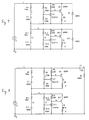
- Fig. 7 is a diagram showing a charge-limiting circuit consisting of two stages.
- Fig. 8 is a diagram showing a full charge-detecting circuit consisting of two stages.
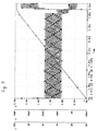
- Fig. 9 shows the results of an analysis made by simulating the full charge-detecting circuit shown in Fig. 8.
- a charge-limiting circuit and a differentiating circuit consisting of CT and RT are connected in parallel with an electric double layer capacitor C1 having an internal resistance of R1.
- the charge-limiting circuit comprises a three-terminal shunt regulator ICX1, a transistor Q1, a Schottky diode D1, and resistors R2-R5.
- the charge-limiting circuit causes the current to bypass the capacitor. This fully charged condition is detected by the differentiating circuit. This detection is performed by superimposing an AC waveform on the charging power supply I1.
- Fig. 6 shows waveforms during the charge process of an electric double layer capacitor used in power applications.
- the capacitor with an electrostatic capacitance of 300F, maximum working voltage of 50V, and an electric capacity of 100WH, is charged from completely discharged condition by a charging current of 2 A.
- the voltage across the terminal of capacitor is indicated by V(1) and the current through the resister R5 in the charge-limiting circuit is I(R5).
- the terminal voltage at the at the resistor RT in the differentiating circuit is indicated by V(9) in Fig. 6.
- a ripple current having a frequency of 10 MHz and an amplitude of 0.5 A is superimposed. This extraordinary low ripple frequency permits the waveform showing the result of an analysis clearly in those figures.
- ripple current from a rectifier circuit used for AC power line can be used.
- the charging voltage approaches 50 V when a charging operation persists for 7400 seconds.
- the current I(5) flowing through the resistor R5 and the terminal voltage V(9) at the resistor RT change violently. Therefore, a fully charged condition can be easily known by detecting these changes.
- the configuration shown in Fig. 7 is built for electrical power applications as described below.
- the electric double layer capacitors C1 and C11 are connected in series.
- the charge-limiting circuit consisting of the components R2-R5, X1, Q1, and D11 and the charge-limiting circuit consisting of components R12-15, X11, Q11, and D11 are connected with the capacitors, respectively.
- the charge-limiting circuit connected with the capacitor turns on the bypass circuit.
- all the capacitors are prevented from being applied with a voltage exceeding the rated value.
- the voltages of the cells are monitored and can be made uniform. Consequently, the power supply can be used up to the rated value safely.
- the fully charged condition can be detected precisely by detecting the condition in which all the charge-limiting circuits connected in series via the differentiating circuit consisting of CT and RT as shown in Fig. 8 have been operated.
- the following methods can be used to sense that a storage capacitor power supply having a plurality of electric double layer capacitors connected in series, in parallel or in any combination of series and parallel has been fully charged.
- signals are taken from all the charge-limiting circuits connected with the capacitors. These signals are ANDed to sense that all the capacitors have reached their rated conditions. In this state, the power supply is regarded as being fully charged.
- the operating points of all the charge-limiting circuits connected with the capacitors are previously set within a given tolerance, e.g., 5%, using techniques of inspection and quality control. One of the capacitors is selected.
- the power supply is regarded as being fully charged.
- an AC waveform or a pulse waveform issuperimposed on the currents produced from current regulation circuits or pseudo-current regulation circuits used for the charging of the capacitors.
- the amplitudes are monitored to detect the fully charged condition.
- the amplitudes decrease suddenly when all the capacitors connected as loads are fully charged and all the charge-limiting circuits turn on the bypass circuits. This point is detected to detect the fully charged condition of the power supply.
- the novel storage capacitor power supply rarely employs only one electric double layer capacitor.
- plural electric double layer capacitors are connected in series to form a block.
- such series combinations of the capacitors are connected in parallel to form a block.
- Ca is the capacitance of the capacitor block A
- Va is the voltage developed across the capacitor block
- Cb is the capacitance of the capacitor block B
- Vb is the voltage developed across the capacitor block B.
- Fig. 10 shows a residual electricity-detecting circuit used in the novel storage capacitor power supply.
- Fig. 11 shows the results of an analysis performed by simulating charging-and-discharging characteristics.
- Fig. 10(A) shows a circuit comprising a multiplier X1 and an operational amplifier U2.
- the multiplier X1 calculates the square of V.
- the calculated square is multiplied by a constant factor by means of the operational amplifier U2.
- the circuit produces a signal indicating the residual capacity.
- the multiplier X1 and a resistor R2 are provided for each capacitor or each capacitor block and connected with a node 3.
- a signal indicating the sum of the residual electric powers can be taken from the outputs from the operational amplifiers U2.
- a resistor R5, a light-emitting diode D1, and a zener diode D2 are connected in series with an electric double layer capacitor C2 and its internal resistance R4 to roughly represent the residual electric power by means of a light quantity.
- the resistor R5 is used as a current-limiting resistor which adjusts the gradient, or the brightness of the light-emitting diode D1.
- an indicator can be used instead of the light-emitting diode D1.
- any other voltage regulation device or constant-voltage source can be used as long as it forms a voltage regulator circuit.
- the line A of Fig. 11 indicates the voltage developed across the terminals of an electric double layer capacitor having an electrostatic capacitance of 300 F, a maximum working voltage of 50 V, and an electric energy of about 100 WH. At the beginning, the capacitor is fully discharged. Then, it is charged with a current of 2 A.
- the line B of Fig. 11 indicates the residual electric power calculated, using the equation described above.
- the line C of Fig. 11 is obtained by superimposing a straight line on the line B. This characteristic is derived by connecting a zener diode of about 18 V in series with the terminal voltage V(1). It can be seen that the residual electric power can be measured with practical accuracy from the fully charged condition to about 3/4 of the range downwardly.
- the present invention is not limited to the above-described embodiments and that various changes and modifications are possible.
- the means which turns on and off the circuit is merely a switch.
- a semiconductor switching device such as a thyristor or a transistor or other switching device may be used.
- the application of the novel electric double layer capacitor is not limited to the power supply of an electric vehicle.
- the novel power supply can also be used as the power supply of an electric welder or other electrically powered machine, as the power supply of a portable electrical appliance such as a flash lamp, radio receiver, television receiver, or video camera.
- the charging of each capacitor is controlled to the full charge level by the voltage across the terminals of the capacitor. Therefore, the electrical energy can be stored effectively. Also, the efficiency at which the storage capacitor power supply supplies electric power can be enhanced. Furthermore, the capacitors can be prevented from being applied with voltages exceeding the rated voltage. Consequently, where the power supply is used to store electricity, decreases in the capacitances of the capacitors, increase in the leakage current, and other problems can be prevented.
Priority Applications (1)
| Application Number | Priority Date | Filing Date | Title |
|---|---|---|---|
| EP96202256A EP0744809B1 (fr) | 1992-04-03 | 1993-03-24 | Alimentation d'énergie avec condensateur de stockage |
Applications Claiming Priority (6)
| Application Number | Priority Date | Filing Date | Title |
|---|---|---|---|
| JP82174/92 | 1992-04-03 | ||
| JP82173/92 | 1992-04-03 | ||
| JP4082174A JPH05292684A (ja) | 1992-04-03 | 1992-04-03 | 動力用蓄電電源装置 |
| JP4082173A JPH05292683A (ja) | 1992-04-03 | 1992-04-03 | 動力用蓄電電源装置 |
| JP04346793A JP3764175B2 (ja) | 1993-03-04 | 1993-03-04 | 蓄電電源装置 |
| JP43467/93 | 1993-03-04 |
Related Child Applications (2)
| Application Number | Title | Priority Date | Filing Date |
|---|---|---|---|
| EP96202256A Division EP0744809B1 (fr) | 1992-04-03 | 1993-03-24 | Alimentation d'énergie avec condensateur de stockage |
| EP96202256.2 Division-Into | 1996-08-10 |
Publications (3)
| Publication Number | Publication Date |
|---|---|
| EP0564149A2 true EP0564149A2 (fr) | 1993-10-06 |
| EP0564149A3 EP0564149A3 (en) | 1994-08-24 |
| EP0564149B1 EP0564149B1 (fr) | 1997-09-24 |
Family
ID=27291555
Family Applications (2)
| Application Number | Title | Priority Date | Filing Date |
|---|---|---|---|
| EP93302233A Expired - Lifetime EP0564149B1 (fr) | 1992-04-03 | 1993-03-24 | Alimentation d'énergie avec condensateur de stockage |
| EP96202256A Expired - Lifetime EP0744809B1 (fr) | 1992-04-03 | 1993-03-24 | Alimentation d'énergie avec condensateur de stockage |
Family Applications After (1)
| Application Number | Title | Priority Date | Filing Date |
|---|---|---|---|
| EP96202256A Expired - Lifetime EP0744809B1 (fr) | 1992-04-03 | 1993-03-24 | Alimentation d'énergie avec condensateur de stockage |
Country Status (3)
| Country | Link |
|---|---|
| US (3) | US5783928A (fr) |
| EP (2) | EP0564149B1 (fr) |
| DE (2) | DE69314079T2 (fr) |
Cited By (21)
| Publication number | Priority date | Publication date | Assignee | Title |
|---|---|---|---|---|
| EP0657985A1 (fr) * | 1993-12-10 | 1995-06-14 | Csee-Defense | Système pour alimenter une charge en énergie électrique à partir d'une source principale et d'une source auxiliaire |
| US5604426A (en) * | 1993-06-30 | 1997-02-18 | Asahi Glass Company Ltd. | Electric apparatus with a power supply including an electric double layer capacitor |
| DE19618039A1 (de) * | 1996-05-04 | 1997-11-06 | Walter Ing Grad Markert | Schaltungsanordnung mit elektrischem Kurzzeitspeicher zum Antrieb von Pumpen und Ventilatoren mittels elektrischem Strom aus Solar- und/oder Windgeneratoren |
| EP1035627A1 (fr) * | 1999-03-09 | 2000-09-13 | Asahi Glass Company Ltd. | Appareil comprenant plusieurs condensateurs électriques à double couche et méthode pour ajuster les tensions des condensateurs |
| FR2796216A1 (fr) * | 1999-07-06 | 2001-01-12 | Jean Marc Boutet | Systeme de stockage d'energie electrique |
| WO2001061821A1 (fr) * | 2000-02-18 | 2001-08-23 | Epcos Ag | Circuit comportant une chaine de condensateurs |
| EP1153788A1 (fr) * | 1998-12-18 | 2001-11-14 | Nissan Diesel Co., Ltd. | Systeme d'entrainement hybride |
| WO2002081255A1 (fr) * | 2001-04-05 | 2002-10-17 | Electrovaya Inc. | Dispositif de stockage d'energie pour des charges a variation de l'electricite fournie |
| EP1291999A1 (fr) * | 2000-04-13 | 2003-03-12 | Makita Corporation | Adaptateur pour chargeur de batterie |
| WO2005027345A1 (fr) * | 2003-09-15 | 2005-03-24 | Electrovaya Inc. | Dispositif de stockage d'energie pour des charges a consommation de puissance variable |
| DE10036519B4 (de) * | 2000-07-27 | 2005-09-01 | Forschungszentrum Karlsruhe Gmbh | Verfahren zur Steuerung einer steuerbaren Stromquelle und einer steuerbaren Spannungsquelle zum Laden der Energiespeicher eines Leistungsmodulators |
| EP1775154A2 (fr) * | 2001-04-05 | 2007-04-18 | Electrovaya Inc. | Dispositif de stockage d'énergie pour des charges à puissance variable |
| EP1843423A2 (fr) * | 1998-07-01 | 2007-10-10 | Relion, Inc. | Procédé de contournement d'une pile à combustible défectueuse |
| FR2925783A1 (fr) * | 2007-12-21 | 2009-06-26 | Peugeot Citroen Automobiles Sa | Systeme de charge/decharge d'au moins une cellule de stockage |
| US8269469B2 (en) | 2008-08-12 | 2012-09-18 | Ivus Industries, Llc | Equalizing method and circuit for ultracapacitors |
| CN104769827A (zh) * | 2012-11-07 | 2015-07-08 | 沃尔沃卡车公司 | 电源装置 |
| EP2206125B1 (fr) * | 2007-10-29 | 2016-02-17 | Egon Evertz K.G. (GmbH & CO) | Aimant de levage de charges et procede d'alimentation electrique de secours |
| CN105539183A (zh) * | 2015-12-30 | 2016-05-04 | 河南顺之航能源科技有限公司 | 全智能化电池组管理系统 |
| CN106299496A (zh) * | 2015-06-01 | 2017-01-04 | 鑫汎股份有限公司 | 铅酸蓄电池硫化储电失效的再生修复方法 |
| CN110745026A (zh) * | 2019-11-04 | 2020-02-04 | 武昌首义学院 | 一种智能充电桩 |
| EP3842277A1 (fr) * | 2019-12-24 | 2021-06-30 | Vito NV | Machine électrique dotée de dispositifs de stockage d'énergie hybride |
Families Citing this family (124)
| Publication number | Priority date | Publication date | Assignee | Title |
|---|---|---|---|---|
| US5977748A (en) * | 1992-04-03 | 1999-11-02 | Jeol Ltd. | Storage capacitor power supply and method of operating same |
| FR2743953B1 (fr) * | 1996-01-19 | 1998-04-10 | Sgs Thomson Microelectronics | Circuit d'alimentation a condensateur de stockage |
| US5734205A (en) * | 1996-04-04 | 1998-03-31 | Jeol Ltd. | Power supply using batteries undergoing great voltage variations |
| JPH1094182A (ja) * | 1996-09-13 | 1998-04-10 | Honda Motor Co Ltd | 電源装置および電気自動車 |
| US5742150A (en) * | 1996-09-16 | 1998-04-21 | Khuwatsamrit; Thakoengdet | Power supply and method of protecting batteries therein |
| US5786685A (en) * | 1997-01-15 | 1998-07-28 | Lockheed Martin Corporation | Accurate high voltage energy storage and voltage limiter |
| JPH10271611A (ja) * | 1997-03-25 | 1998-10-09 | Nissan Diesel Motor Co Ltd | 電気自動車の電源システム |
| US6034492A (en) * | 1997-04-30 | 2000-03-07 | Nec Corporation | Motor-generator |
| JPH1118322A (ja) * | 1997-06-24 | 1999-01-22 | Okamura Kenkyusho:Kk | ターンオン機能を持つ並列モニタ |
| JPH1127859A (ja) * | 1997-06-30 | 1999-01-29 | Nec Corp | 電源回路 |
| US5982144A (en) * | 1997-07-14 | 1999-11-09 | Johnson Research & Development Company, Inc. | Rechargeable battery power supply overcharge protection circuit |
| US6387556B1 (en) | 1997-11-20 | 2002-05-14 | Avista Laboratories, Inc. | Fuel cell power systems and methods of controlling a fuel cell power system |
| WO1999048184A1 (fr) * | 1998-03-19 | 1999-09-23 | Seiko Epson Corporation | Procede de prevention des surcharges, circuit chargeur, dispositif electronique et compteur de temps |
| US6157167A (en) * | 1998-04-29 | 2000-12-05 | The Johns Hopkins University | Topology for individual battery cell charge control in a rechargeable battery cell array |
| JP3410022B2 (ja) * | 1998-05-20 | 2003-05-26 | 本田技研工業株式会社 | ハイブリッド車両の制御装置 |
| FR2780684B1 (fr) * | 1998-07-02 | 2002-02-01 | Anf Ind | Reseau de transport en commun avec vehicules electriques |
| DE19832874C2 (de) * | 1998-07-22 | 2000-10-26 | Daimler Chrysler Ag | Energieversorgungseinrichtung für eine elektromagnetische Ventilsteuerung einer Brennkraftmaschine |
| US6087811A (en) * | 1998-12-09 | 2000-07-11 | Analog Modules, Inc. | Pulsed-output power supply with high power factor |
| IL127932A (en) | 1999-01-05 | 2004-03-28 | Rafael Armanent Dev Authority | Melting resistors with an electrochemical capacitor as the source of the electric current |
| US6388392B1 (en) | 1999-03-23 | 2002-05-14 | Hubbell Incorporated | System for providing auxiliary power to lighting unit for heavy equipment having a direct current power supply and no uninterruptible power supply |
| US6398824B1 (en) | 1999-04-02 | 2002-06-04 | Excellatron Solid State, Llc | Method for manufacturing a thin-film lithium battery by direct deposition of battery components on opposite sides of a current collector |
| US6242129B1 (en) | 1999-04-02 | 2001-06-05 | Excellatron Solid State, Llc | Thin lithium film battery |
| BG103377A (en) * | 1999-04-30 | 2001-04-30 | Христо РИБАРЕВ | Device for energy accumulation and recuperation in electrically driven motor transport vehicles |
| US6615147B1 (en) | 1999-08-09 | 2003-09-02 | Power Measurement Ltd. | Revenue meter with power quality features |
| JP3373459B2 (ja) * | 1999-09-07 | 2003-02-04 | 本田技研工業株式会社 | ハイブリッド自動車の制御装置 |
| US6511516B1 (en) | 2000-02-23 | 2003-01-28 | Johnson Research & Development Co., Inc. | Method and apparatus for producing lithium based cathodes |
| US6582481B1 (en) | 1999-11-23 | 2003-06-24 | Johnson Research & Development Company, Inc. | Method of producing lithium base cathodes |
| JP3507384B2 (ja) * | 1999-12-28 | 2004-03-15 | 株式会社岡村研究所 | 初期化機能付きキャパシタ蓄電装置 |
| US6654228B1 (en) | 2000-03-08 | 2003-11-25 | Eveready Battery Company, Inc. | Energy storage device having DC voltage converter |
| FR2806673B1 (fr) * | 2000-03-27 | 2002-06-14 | De Villemeur Philippe Billette | Moyen de transport collectif urbain electrique a itineraire multiple alimente par le reseau general |
| US6387563B1 (en) | 2000-03-28 | 2002-05-14 | Johnson Research & Development, Inc. | Method of producing a thin film battery having a protective packaging |
| IL151275A0 (en) * | 2000-03-31 | 2003-04-10 | Inventio Ag | Device and method for reducing the power of the supply connection in lift systems |
| US6423106B1 (en) | 2000-04-05 | 2002-07-23 | Johnson Research & Development | Method of producing a thin film battery anode |
| US6428918B1 (en) | 2000-04-07 | 2002-08-06 | Avista Laboratories, Inc. | Fuel cell power systems, direct current voltage converters, fuel cell power generation methods, power conditioning methods and direct current power conditioning methods |
| AUPQ750500A0 (en) * | 2000-05-15 | 2000-06-08 | Energy Storage Systems Pty Ltd | A power supply |
| AUPQ750400A0 (en) * | 2000-05-15 | 2000-06-08 | Energy Storage Systems Pty Ltd | A power supply |
| DE10025834B4 (de) * | 2000-05-25 | 2005-07-14 | Hilti Ag | Einrichtung zur Erzeugung einer rauscharmen geregelten Hochspannung aus einer Niedervolt-Versorgungsquelle |
| FR2810278B1 (fr) * | 2000-06-19 | 2002-10-11 | Renault Vehicules Ind | Systeme d'alimentation en energie de vehicules a traction electrique |
| US20020110733A1 (en) * | 2000-08-07 | 2002-08-15 | Johnson Lonnie G. | Systems and methods for producing multilayer thin film energy storage devices |
| US6402796B1 (en) | 2000-08-07 | 2002-06-11 | Excellatron Solid State, Llc | Method of producing a thin film battery |
| JP3526028B2 (ja) * | 2000-10-18 | 2004-05-10 | Necトーキン株式会社 | 電源回路、電源回路の制御方法、及びこの電源回路を用いた電子機器 |
| JP3898889B2 (ja) * | 2000-12-19 | 2007-03-28 | ペンタックス株式会社 | 電源補助ユニット及び携帯機器システム |
| US6998822B2 (en) * | 2001-05-15 | 2006-02-14 | Energy Storage Systems Pty Ltd | Power supply for a pulsed load |
| US6630259B2 (en) | 2001-05-23 | 2003-10-07 | Avista Laboratories, Inc. | Fuel cell power system performing AC inversion, method of distributing AC power, and method of operating a fuel cell power system |
| US6497974B2 (en) * | 2001-05-23 | 2002-12-24 | Avista Laboratories, Inc. | Fuel cell power system, method of distributing power, and method of operating a fuel cell power system |
| JP2003032908A (ja) * | 2001-07-19 | 2003-01-31 | Nisshinbo Ind Inc | キャパシタ組電池、その制御方法、その制御装置及び自動車用蓄電システム |
| US6628107B1 (en) * | 2001-10-31 | 2003-09-30 | Symbol Technologies, Inc. | Power management for a portable electronic device |
| US6703155B2 (en) | 2001-11-13 | 2004-03-09 | Avista Laboratories, Inc. | Power tap device, fuel cell stack, and method of dividing a fuel cell stack |
| US20070094865A1 (en) * | 2002-01-10 | 2007-05-03 | Ji-Guang Zhang | Packaged thin film batteries and methods of packaging thin film batteries |
| US7204862B1 (en) | 2002-01-10 | 2007-04-17 | Excellatron Solid State, Llc | Packaged thin film batteries and methods of packaging thin film batteries |
| US7960054B2 (en) * | 2002-01-10 | 2011-06-14 | Excellatron Solid State Llc | Packaged thin film batteries |
| US20030184926A1 (en) * | 2002-04-01 | 2003-10-02 | Uis Abler Electronics Co., Ltd. | Hybrid switch module for an AC power capacitor |
| EP1523222B1 (fr) * | 2002-07-12 | 2015-05-06 | Ricoh Company, Ltd. | Appareil de chauffage, appareil et systeme d'alimentation electrique auxiliaire, appareil de fixation et appareil de formation d'images mobiles |
| JP2004056881A (ja) * | 2002-07-18 | 2004-02-19 | Denso Corp | 車両用発電機の制御装置および車両用電源システム |
| DE10244508A1 (de) * | 2002-09-25 | 2004-04-08 | Hilti Ag | Handgeführtes Arbeitsgerät, insbesondere brennkraftbetriebenes Setzgerät |
| US6960838B2 (en) * | 2002-11-15 | 2005-11-01 | Sprint Communications Company L.P. | Power system for a telecommunication facility |
| US7275501B1 (en) * | 2003-07-03 | 2007-10-02 | Laceky William P | System and method using capacitors to power an automatic feeder system |
| US8525469B1 (en) | 2003-07-03 | 2013-09-03 | Battery-Free Outdoors, Llc | System and method using capacitors to power a camera having a motion sensor |
| DE10331084A1 (de) * | 2003-07-09 | 2005-03-24 | Aloys Wobben | Kraftfahrzeug |
| US6886240B2 (en) * | 2003-07-11 | 2005-05-03 | Excellatron Solid State, Llc | Apparatus for producing thin-film electrolyte |
| US6852139B2 (en) | 2003-07-11 | 2005-02-08 | Excellatron Solid State, Llc | System and method of producing thin-film electrolyte |
| AU2004314847A1 (en) * | 2004-01-29 | 2005-08-11 | Bozidar Konjevic Lisac | Method and device for supplying a charge with electric energy recovery |
| US20080070087A1 (en) * | 2004-02-20 | 2008-03-20 | Excellatron Solid State, Llc | Non-volatile cathodes for lithium oxygen batteries and method of producing same |
| US10566669B2 (en) | 2004-02-20 | 2020-02-18 | Johnson Ip Holding, Llc | Lithium oxygen batteries having a carbon cloth current collector and method of producing same |
| US7691536B2 (en) * | 2004-02-20 | 2010-04-06 | Excellatron Solid State, Llc | Lithium oxygen batteries and method of producing same |
| US7731765B2 (en) | 2004-02-20 | 2010-06-08 | Excellatron Solid State, Llc | Air battery and manufacturing method |
| JP4721647B2 (ja) * | 2004-03-18 | 2011-07-13 | 東芝エレベータ株式会社 | エレベータ制御装置 |
| JP4078650B2 (ja) * | 2004-03-30 | 2008-04-23 | 株式会社リコー | 並列モニタ回路およびそれを用いた半導体装置 |
| US6972921B1 (en) | 2004-04-05 | 2005-12-06 | Marvell International Ltd. | Circuit and method for protecting emergency head-retract |
| FR2869469B1 (fr) * | 2004-04-23 | 2006-10-20 | Peugeot Citroen Automobiles Sa | Dispositif de protection de reseau de bord |
| US7696089B1 (en) | 2004-05-11 | 2010-04-13 | Johnson Research & Development Co., Inc. | Passivated thin film and method of producing same |
| JP4378224B2 (ja) * | 2004-06-04 | 2009-12-02 | 株式会社ミクニ | 電源装置 |
| US7481728B2 (en) | 2004-06-29 | 2009-01-27 | Siemens Energy & Automation, Inc. | System and apparatus for driving a track mounted robot |
| US8568921B1 (en) | 2004-08-18 | 2013-10-29 | Excellatron Solid State Llc | Regenerative ion exchange fuel cell |
| US7323849B1 (en) * | 2004-10-22 | 2008-01-29 | Robinett Mark I | Rechargeable portable light with multiple charging systems |
| US20080174989A1 (en) * | 2004-10-22 | 2008-07-24 | Mark Robinett | Rechargeable Portable Light with Multiple Charging Systems |
| JP4218050B2 (ja) * | 2004-11-30 | 2009-02-04 | 本田技研工業株式会社 | 電圧測定装置および電圧測定方法 |
| US7425834B2 (en) * | 2005-08-26 | 2008-09-16 | Power Integrations, Inc. | Method and apparatus to select a parameter/mode based on a time measurement |
| KR20080087782A (ko) * | 2005-10-11 | 2008-10-01 | 엑셀라트론 솔리드 스테이트 엘엘씨 | 리튬 배터리 제조 방법 |
| US20070087241A1 (en) * | 2005-10-18 | 2007-04-19 | General Hydrogen Corporation | Fuel cell power pack |
| US7477505B2 (en) * | 2005-10-18 | 2009-01-13 | General Hydrogen Corporation | Capacitor bank for electrical generator |
| US20070087239A1 (en) * | 2005-10-18 | 2007-04-19 | General Hydrogen Corporation | Fuel cell fluid management system |
| JP4864427B2 (ja) * | 2005-11-16 | 2012-02-01 | ローム株式会社 | 電気二重層コンデンサの製造方法 |
| US20070141428A1 (en) * | 2005-12-16 | 2007-06-21 | Skidmore Dustan L | Preventing backfeeding of current to a fuel cell stack from energy storage |
| US7915854B2 (en) * | 2005-12-16 | 2011-03-29 | Plug Power Inc. | Maximizing energy storage life in a fuel cell system using active temperature compensation |
| US20070141429A1 (en) * | 2005-12-16 | 2007-06-21 | Robertson David M | Storing energy in a fuel cell system |
| JP4568736B2 (ja) | 2007-02-27 | 2010-10-27 | 三菱重工業株式会社 | 架線レス交通システム及びその充電方法 |
| TW200847580A (en) * | 2007-04-04 | 2008-12-01 | Cooper Technologies Co | System and method for boosting battery output |
| US20120196189A1 (en) | 2007-06-29 | 2012-08-02 | Johnson Ip Holding, Llc | Amorphous ionically conductive metal oxides and sol gel method of preparation |
| US8211496B2 (en) * | 2007-06-29 | 2012-07-03 | Johnson Ip Holding, Llc | Amorphous lithium lanthanum titanate thin films manufacturing method |
| US9034525B2 (en) * | 2008-06-27 | 2015-05-19 | Johnson Ip Holding, Llc | Ionically-conductive amorphous lithium lanthanum zirconium oxide |
| US20090092903A1 (en) * | 2007-08-29 | 2009-04-09 | Johnson Lonnie G | Low Cost Solid State Rechargeable Battery and Method of Manufacturing Same |
| WO2009027962A2 (fr) * | 2007-09-02 | 2009-03-05 | Orziv - Design And Development | Système de rattrapage pour interrupteur électrique télécommandé |
| US20090239132A1 (en) * | 2008-03-20 | 2009-09-24 | Excellatron Solid State, Llc | Oxygen battery system |
| CN101561469A (zh) * | 2008-04-18 | 2009-10-21 | 鸿富锦精密工业(深圳)有限公司 | 充电器负载模拟装置 |
| US20090309538A1 (en) * | 2008-06-16 | 2009-12-17 | Jian Xu | Energy storage and management circuit |
| TWI472120B (zh) * | 2008-07-23 | 2015-02-01 | Koninkl Philips Electronics Nv | 用於對超級電容器充電之方法及充電器 |
| US8116106B2 (en) * | 2008-09-19 | 2012-02-14 | Power Integrations, Inc. | Method and apparatus to select a parameter/mode based on a measurement during an initialization period |
| JP4914417B2 (ja) * | 2008-10-15 | 2012-04-11 | 株式会社エヌ・ピー・シー | ソーラーシミュレータ |
| ITMI20090373A1 (it) * | 2009-03-12 | 2010-09-13 | Maria Chiara Nicolo' | Dispositivo e procedimento atto a generare energia elettrica che utilizza soluzioni con differente concentrazione ionica |
| CN102449872B (zh) * | 2009-06-29 | 2016-07-06 | 飞思卡尔半导体公司 | 电池充电电路以及电子装置 |
| DE102009031295A1 (de) * | 2009-06-30 | 2011-01-05 | Fev Motorentechnik Gmbh | Energiespeichervorrichtung |
| WO2011038392A1 (fr) * | 2009-09-28 | 2011-03-31 | A123 Systems, Inc. | Contre-mesure basée sur le stockage d'énergie pour le retard de rétablissement de la tension |
| JP2011087448A (ja) * | 2009-10-19 | 2011-04-28 | Nisshinbo Holdings Inc | 蓄電モジュール制御装置 |
| DE102010025198A1 (de) * | 2010-06-26 | 2011-12-29 | Volkswagen Ag | Kraftfahrzeug-Bordnetz und Verfahren zum Betreiben eines Kraftfahrzeug-Bordnetzes |
| EP2423694B1 (fr) * | 2010-08-31 | 2015-07-01 | ST-Ericsson SA | Procédé pour l'auto-test d'une batterie entièrement déchargée, une telle batterie de condensateur à double couche et circuit correspondant |
| EP2456040A1 (fr) * | 2010-11-19 | 2012-05-23 | Flextronic Int.Kft | Commutateur destiné à stocker une énergie électrique |
| WO2012087895A1 (fr) | 2010-12-22 | 2012-06-28 | Converteam Technology Ltd. | Circuit d'équilibrage de condensateurs et procédé de commande de dispositif électronique tel un onduleur de puissance à plusieurs niveaux |
| BR112013015890A2 (pt) | 2010-12-22 | 2017-09-19 | Ge Energy Power Conversion Technology Ltd | arranjo mecânico de um circuito conversor de potência multinível. |
| US20130015711A1 (en) * | 2011-01-18 | 2013-01-17 | Battery-Free Outdoors, Llc | System and method for using capacitors in remote operations |
| KR20120120706A (ko) * | 2011-04-25 | 2012-11-02 | 삼성전자주식회사 | 보조 전원 장치 및 보조 전원 장치를 포함하는 사용자 장치 |
| JP5942083B2 (ja) * | 2011-12-15 | 2016-06-29 | パナソニックIpマネジメント株式会社 | キャパシタ装置 |
| WO2013131005A2 (fr) | 2012-03-01 | 2013-09-06 | Excellatron Solid State, Llc | Cathode composite à semi-conducteur à haute capacité, séparateur composite à semi-conducteur, pile au lithium rechargeable à semi-conducteur et procédés de fabrication associés |
| DE102012015961A1 (de) * | 2012-08-11 | 2014-02-13 | Udo Sorgatz | Vorrichtung zum Antrieb einer Maschine mit instationärem Leistungsbedarf |
| US10084168B2 (en) | 2012-10-09 | 2018-09-25 | Johnson Battery Technologies, Inc. | Solid-state battery separators and methods of fabrication |
| US9627912B2 (en) | 2012-12-18 | 2017-04-18 | Welch Allyn, Inc. | Mobile cart with capacitive power supply |
| SG11201702267WA (en) | 2014-09-23 | 2017-04-27 | Switchbee Ltd | A method and apparatus for controlling a load |
| US10069468B2 (en) | 2014-12-24 | 2018-09-04 | Panasonic Intellectual Property Management Co., Ltd. | Audio signal amplification device, power supply device, and power supply control method |
| CN114551990A (zh) | 2015-12-21 | 2022-05-27 | 约翰逊Ip控股有限公司 | 固态电池、隔板、电极和制造方法 |
| US10218044B2 (en) | 2016-01-22 | 2019-02-26 | Johnson Ip Holding, Llc | Johnson lithium oxygen electrochemical engine |
| CN106274508A (zh) * | 2016-08-30 | 2017-01-04 | 中车株洲电力机车有限公司 | 一种内燃动车组及其供电系统及牵引控制方法 |
| CN106809041A (zh) * | 2016-12-28 | 2017-06-09 | 广州杰赛科技股份有限公司 | 一种多功能路灯充电桩 |
| CN111164871A (zh) * | 2017-10-09 | 2020-05-15 | 技术创新动力基金(以色列)有限合伙公司 | 虚拟无限电容器的即插即用实现 |
| CN111284362B (zh) * | 2020-03-17 | 2021-08-31 | 南京四象新能源科技有限公司 | 电池管理系统bms的控制电路、电池管理系统及用电设备 |
Citations (3)
| Publication number | Priority date | Publication date | Assignee | Title |
|---|---|---|---|---|
| EP0101017A2 (fr) * | 1982-08-17 | 1984-02-22 | Siemens Aktiengesellschaft | Commutateur temporisateur électronique |
| EP0410559A2 (fr) * | 1989-07-27 | 1991-01-30 | Isuzu Motors Limited | Dispositif d'alimentation électrique |
| WO1992007371A1 (fr) * | 1990-10-12 | 1992-04-30 | Motorola, Inc. | Source d'alimentation capacitive |
Family Cites Families (15)
| Publication number | Priority date | Publication date | Assignee | Title |
|---|---|---|---|---|
| SU608274A1 (ru) * | 1976-01-04 | 1978-05-25 | Предприятие П/Я Г-4147 | Устройство дл питани импульсных газоразр дных ламп |
| US4303877A (en) * | 1978-05-05 | 1981-12-01 | Brown, Boveri & Cie Aktiengesellschaft | Circuit for protecting storage cells |
| DE3045445A1 (de) * | 1980-12-02 | 1982-07-01 | Siemens AG, 1000 Berlin und 8000 München | Schaltungsanordnung zur strom- und spannungsversorgung bei netzausfall |
| US4364396A (en) * | 1981-06-15 | 1982-12-21 | Medtronic, Inc. | Circuit and method for measuring PSA output and energy |
| JPS58201534A (ja) * | 1982-05-18 | 1983-11-24 | 三菱電機株式会社 | 車両用充電制御マイクロコンピユ−タ装置 |
| US4591782A (en) * | 1984-04-12 | 1986-05-27 | General Electric Company | Power supply and power monitor for electric meter |
| US4709200A (en) * | 1985-10-21 | 1987-11-24 | Seiko Instruments & Electronics Ltd. | Power source circuit |
| CH677048A5 (fr) * | 1987-12-10 | 1991-03-28 | Weber Hans R | |
| US5397991A (en) * | 1988-07-13 | 1995-03-14 | Electronic Development Inc. | Multi-battery charging system for reduced fuel consumption and emissions in automotive vehicles |
| JPH0255535A (ja) * | 1988-08-19 | 1990-02-23 | Michiko Takahashi | 静電コンデンサの電源回路 |
| US4937528A (en) * | 1988-10-14 | 1990-06-26 | Allied-Signal Inc. | Method for monitoring automotive battery status |
| US5256956A (en) * | 1988-12-27 | 1993-10-26 | Isuzu Motors Limited | Power supply apparatus for automotive vehicles |
| US5187640A (en) * | 1990-10-12 | 1993-02-16 | Motorola, Inc. | Capacitive power supply |
| JP2685977B2 (ja) * | 1990-11-01 | 1997-12-08 | 株式会社東芝 | 電池電力貯蔵システム制御装置 |
| US5392205A (en) * | 1991-11-07 | 1995-02-21 | Motorola, Inc. | Regulated charge pump and method therefor |
-
1993
- 1993-03-24 EP EP93302233A patent/EP0564149B1/fr not_active Expired - Lifetime
- 1993-03-24 EP EP96202256A patent/EP0744809B1/fr not_active Expired - Lifetime
- 1993-03-24 DE DE69314079T patent/DE69314079T2/de not_active Expired - Fee Related
- 1993-03-24 DE DE69330799T patent/DE69330799T2/de not_active Expired - Lifetime
- 1993-04-02 US US08/041,543 patent/US5783928A/en not_active Expired - Lifetime
-
1995
- 1995-05-31 US US08/454,706 patent/US6424156B1/en not_active Expired - Lifetime
- 1995-05-31 US US08/454,841 patent/US5532572A/en not_active Expired - Lifetime
Patent Citations (3)
| Publication number | Priority date | Publication date | Assignee | Title |
|---|---|---|---|---|
| EP0101017A2 (fr) * | 1982-08-17 | 1984-02-22 | Siemens Aktiengesellschaft | Commutateur temporisateur électronique |
| EP0410559A2 (fr) * | 1989-07-27 | 1991-01-30 | Isuzu Motors Limited | Dispositif d'alimentation électrique |
| WO1992007371A1 (fr) * | 1990-10-12 | 1992-04-30 | Motorola, Inc. | Source d'alimentation capacitive |
Non-Patent Citations (2)
| Title |
|---|
| PATENT ABSTRACTS OF JAPAN vol. 16, no. 472 (E-1272) 30 September 1992 & JP-A-04 168 939 (TOSHIBA) 17 June 1992 * |
| SOVIET INVENTIONS ILLUSTRATED Week 7915, 23 May 1979 Derwent Publications Ltd., London, GB; AN 79-D2705B BOMKO 'supply system for pulse gas-discharge lamp with control voltage limiter and inductance capacitance network energy measuring system to reduce charging current interval' & SU-A-608 274 (BOMKO A.G.) 17 May 1978 * |
Cited By (33)
| Publication number | Priority date | Publication date | Assignee | Title |
|---|---|---|---|---|
| US5604426A (en) * | 1993-06-30 | 1997-02-18 | Asahi Glass Company Ltd. | Electric apparatus with a power supply including an electric double layer capacitor |
| EP0657985A1 (fr) * | 1993-12-10 | 1995-06-14 | Csee-Defense | Système pour alimenter une charge en énergie électrique à partir d'une source principale et d'une source auxiliaire |
| FR2713842A1 (fr) * | 1993-12-10 | 1995-06-16 | Csee Defense Sa | Système pour alimenter une charge en énergie électrique à partir d'une source principale et d'une source auxiliaire. |
| DE19618039A1 (de) * | 1996-05-04 | 1997-11-06 | Walter Ing Grad Markert | Schaltungsanordnung mit elektrischem Kurzzeitspeicher zum Antrieb von Pumpen und Ventilatoren mittels elektrischem Strom aus Solar- und/oder Windgeneratoren |
| EP1843423A3 (fr) * | 1998-07-01 | 2007-10-17 | Relion, Inc. | Procédé de contournement d'une pile à combustible défectueuse |
| EP1843423A2 (fr) * | 1998-07-01 | 2007-10-10 | Relion, Inc. | Procédé de contournement d'une pile à combustible défectueuse |
| EP1153788A1 (fr) * | 1998-12-18 | 2001-11-14 | Nissan Diesel Co., Ltd. | Systeme d'entrainement hybride |
| EP1153788A4 (fr) * | 1998-12-18 | 2003-05-21 | Nissan Diesel | Systeme d'entrainement hybride |
| US6316917B1 (en) | 1999-03-09 | 2001-11-13 | Asahi Glass Company, Limited | Apparatus having plural electric double layer capacitors and method for adjusting voltages of the capacitors |
| EP1035627A1 (fr) * | 1999-03-09 | 2000-09-13 | Asahi Glass Company Ltd. | Appareil comprenant plusieurs condensateurs électriques à double couche et méthode pour ajuster les tensions des condensateurs |
| FR2796216A1 (fr) * | 1999-07-06 | 2001-01-12 | Jean Marc Boutet | Systeme de stockage d'energie electrique |
| WO2001061821A1 (fr) * | 2000-02-18 | 2001-08-23 | Epcos Ag | Circuit comportant une chaine de condensateurs |
| EP1291999A1 (fr) * | 2000-04-13 | 2003-03-12 | Makita Corporation | Adaptateur pour chargeur de batterie |
| EP1291999A4 (fr) * | 2000-04-13 | 2004-07-14 | Makita Corp | Adaptateur pour chargeur de batterie |
| DE10036519B4 (de) * | 2000-07-27 | 2005-09-01 | Forschungszentrum Karlsruhe Gmbh | Verfahren zur Steuerung einer steuerbaren Stromquelle und einer steuerbaren Spannungsquelle zum Laden der Energiespeicher eines Leistungsmodulators |
| CN1304217C (zh) * | 2001-04-05 | 2007-03-14 | 伊莱克特罗维亚公司 | 用于具有可变功率的负载的能量储存装置 |
| EP1775154A2 (fr) * | 2001-04-05 | 2007-04-18 | Electrovaya Inc. | Dispositif de stockage d'énergie pour des charges à puissance variable |
| WO2002081255A1 (fr) * | 2001-04-05 | 2002-10-17 | Electrovaya Inc. | Dispositif de stockage d'energie pour des charges a variation de l'electricite fournie |
| US7570012B2 (en) | 2001-04-05 | 2009-08-04 | Electrovaya Inc. | Energy storage device for loads having variable power rates |
| EP1775154A3 (fr) * | 2001-04-05 | 2014-05-07 | Electrovaya Inc. | Dispositif de stockage d'énergie pour des charges à puissance variable |
| RU2294851C2 (ru) * | 2001-04-05 | 2007-03-10 | Электровайа Инк. | Устройство для хранения электрической энергии и питание ею потребителей непостоянной мощности |
| WO2005027345A1 (fr) * | 2003-09-15 | 2005-03-24 | Electrovaya Inc. | Dispositif de stockage d'energie pour des charges a consommation de puissance variable |
| EP2206125B1 (fr) * | 2007-10-29 | 2016-02-17 | Egon Evertz K.G. (GmbH & CO) | Aimant de levage de charges et procede d'alimentation electrique de secours |
| FR2925783A1 (fr) * | 2007-12-21 | 2009-06-26 | Peugeot Citroen Automobiles Sa | Systeme de charge/decharge d'au moins une cellule de stockage |
| US8269469B2 (en) | 2008-08-12 | 2012-09-18 | Ivus Industries, Llc | Equalizing method and circuit for ultracapacitors |
| CN104769827A (zh) * | 2012-11-07 | 2015-07-08 | 沃尔沃卡车公司 | 电源装置 |
| CN106299496A (zh) * | 2015-06-01 | 2017-01-04 | 鑫汎股份有限公司 | 铅酸蓄电池硫化储电失效的再生修复方法 |
| CN106299496B (zh) * | 2015-06-01 | 2018-11-23 | 烽曜股份有限公司 | 铅酸蓄电池硫化储电失效的再生修复方法 |
| CN105539183A (zh) * | 2015-12-30 | 2016-05-04 | 河南顺之航能源科技有限公司 | 全智能化电池组管理系统 |
| CN110745026A (zh) * | 2019-11-04 | 2020-02-04 | 武昌首义学院 | 一种智能充电桩 |
| CN110745026B (zh) * | 2019-11-04 | 2021-04-02 | 武昌首义学院 | 一种智能充电桩 |
| EP3842277A1 (fr) * | 2019-12-24 | 2021-06-30 | Vito NV | Machine électrique dotée de dispositifs de stockage d'énergie hybride |
| WO2021130174A1 (fr) * | 2019-12-24 | 2021-07-01 | Vito Nv | Machine électrique dotée de dispositifs de stockage d'énergie hybride |
Also Published As
| Publication number | Publication date |
|---|---|
| EP0744809B1 (fr) | 2001-09-19 |
| US6424156B1 (en) | 2002-07-23 |
| EP0564149B1 (fr) | 1997-09-24 |
| DE69330799D1 (de) | 2001-10-25 |
| EP0564149A3 (en) | 1994-08-24 |
| US5783928A (en) | 1998-07-21 |
| DE69314079D1 (de) | 1997-10-30 |
| EP0744809A3 (fr) | 1997-06-04 |
| DE69330799T2 (de) | 2002-05-29 |
| US5532572A (en) | 1996-07-02 |
| DE69314079T2 (de) | 1998-03-26 |
| EP0744809A2 (fr) | 1996-11-27 |
Similar Documents
| Publication | Publication Date | Title |
|---|---|---|
| EP0564149B1 (fr) | Alimentation d'énergie avec condensateur de stockage | |
| US6809433B2 (en) | Capacitor unit with electric double layer capacitors, control method and control apparatus for the same, and accumulator system for motor vehicles | |
| US6982540B2 (en) | Energy management system for a motor vehicle electrical system | |
| CA2538299C (fr) | Dispositif de stockage d'energie pour des charges a consommation de puissance variable | |
| CN101385186B (zh) | 高效运行的混合型电池组 | |
| EP2702662A2 (fr) | Système de batterie et son procédé de commande | |
| JPH06283210A (ja) | 蓄電装置及び電力システム | |
| US5977748A (en) | Storage capacitor power supply and method of operating same | |
| EP1296435A2 (fr) | Accumulateur et méthode de contrôle de la charge d'un bloc accumulateur | |
| Andreev | An overview of supercapacitors as new power sources in hybrid energy storage systems for electric vehicles | |
| CN110884364A (zh) | 一种基于功率跟踪的电动汽车混合电源控制方法 | |
| CN105794073A (zh) | 充放电系统 | |
| JP3764175B2 (ja) | 蓄電電源装置 | |
| CN113479076B (zh) | 燃料电池增程式混合电动汽车供电系统 | |
| KR101567557B1 (ko) | 이차 전지 셀의 전압 벨런싱 장치 및 방법 | |
| CN110293849A (zh) | 电动汽车 | |
| JP3994812B2 (ja) | 電源システム | |
| CN110024212B (zh) | 复合电池、具备其的机动车及铁道再生电力储存装置 | |
| CN111204225B (zh) | 机车电容在线检测及监控装置 | |
| JPH05292683A (ja) | 動力用蓄電電源装置 | |
| Nomoto et al. | Back-up Performance of Electric Double-Layer Capacitors for Rechargeable Batteries | |
| Babar et al. | Hybrid Energy Control for an Electric Vehicle Using Super Capacitor and Battery | |
| Lencwe et al. | Towards performance enhancement of lead-acid battery for modern transport vehicles | |
| Nair et al. | A novel fast charging technique using supercapacitors | |
| Swarnkar et al. | Performance analysis of hybrid fuel cell/battery/supercapacitor electric vehicle for different battery state of charge levels |
Legal Events
| Date | Code | Title | Description |
|---|---|---|---|
| PUAI | Public reference made under article 153(3) epc to a published international application that has entered the european phase |
Free format text: ORIGINAL CODE: 0009012 |
|
| AK | Designated contracting states |
Kind code of ref document: A2 Designated state(s): DE FR GB IT |
|
| PUAL | Search report despatched |
Free format text: ORIGINAL CODE: 0009013 |
|
| AK | Designated contracting states |
Kind code of ref document: A3 Designated state(s): DE FR GB IT |
|
| 17P | Request for examination filed |
Effective date: 19940902 |
|
| 17Q | First examination report despatched |
Effective date: 19960105 |
|
| GRAG | Despatch of communication of intention to grant |
Free format text: ORIGINAL CODE: EPIDOS AGRA |
|
| GRAH | Despatch of communication of intention to grant a patent |
Free format text: ORIGINAL CODE: EPIDOS IGRA |
|
| GRAH | Despatch of communication of intention to grant a patent |
Free format text: ORIGINAL CODE: EPIDOS IGRA |
|
| GRAA | (expected) grant |
Free format text: ORIGINAL CODE: 0009210 |
|
| ITF | It: translation for a ep patent filed |
Owner name: BARZANO' E ZANARDO ROMA S.P.A. |
|
| AK | Designated contracting states |
Kind code of ref document: B1 Designated state(s): DE FR GB IT |
|
| XX | Miscellaneous (additional remarks) |
Free format text: TEILANMELDUNG 96202256.2 EINGEREICHT AM 10/08/96. |
|
| ET | Fr: translation filed | ||
| REF | Corresponds to: |
Ref document number: 69314079 Country of ref document: DE Date of ref document: 19971030 |
|
| PLBE | No opposition filed within time limit |
Free format text: ORIGINAL CODE: 0009261 |
|
| STAA | Information on the status of an ep patent application or granted ep patent |
Free format text: STATUS: NO OPPOSITION FILED WITHIN TIME LIMIT |
|
| 26N | No opposition filed | ||
| REG | Reference to a national code |
Ref country code: GB Ref legal event code: IF02 |
|
| REG | Reference to a national code |
Ref country code: GB Ref legal event code: 732E |
|
| REG | Reference to a national code |
Ref country code: FR Ref legal event code: TP |
|
| REG | Reference to a national code |
Ref country code: DE Ref legal event code: R409 Ref document number: 69314079 Country of ref document: DE Ref country code: DE Ref legal event code: R119 Ref document number: 69314079 Country of ref document: DE |
|
| REG | Reference to a national code |
Ref country code: DE Ref legal event code: R409 Ref document number: 69314079 Country of ref document: DE |
|
| PGFP | Annual fee paid to national office [announced via postgrant information from national office to epo] |
Ref country code: FR Payment date: 20120319 Year of fee payment: 20 |
|
| PGFP | Annual fee paid to national office [announced via postgrant information from national office to epo] |
Ref country code: IT Payment date: 20120317 Year of fee payment: 20 Ref country code: GB Payment date: 20120321 Year of fee payment: 20 |
|
| PGFP | Annual fee paid to national office [announced via postgrant information from national office to epo] |
Ref country code: DE Payment date: 20120411 Year of fee payment: 20 |
|
| REG | Reference to a national code |
Ref country code: DE Ref legal event code: R071 Ref document number: 69314079 Country of ref document: DE |
|
| REG | Reference to a national code |
Ref country code: DE Ref legal event code: R071 Ref document number: 69314079 Country of ref document: DE |
|
| REG | Reference to a national code |
Ref country code: GB Ref legal event code: PE20 Expiry date: 20130323 |
|
| PG25 | Lapsed in a contracting state [announced via postgrant information from national office to epo] |
Ref country code: DE Free format text: LAPSE BECAUSE OF EXPIRATION OF PROTECTION Effective date: 20130326 Ref country code: GB Free format text: LAPSE BECAUSE OF EXPIRATION OF PROTECTION Effective date: 20130323 |