EP0563869B1 - Filtersackmuffe für einen Schmutzsauger - Google Patents
Filtersackmuffe für einen Schmutzsauger Download PDFInfo
- Publication number
- EP0563869B1 EP0563869B1 EP93105203A EP93105203A EP0563869B1 EP 0563869 B1 EP0563869 B1 EP 0563869B1 EP 93105203 A EP93105203 A EP 93105203A EP 93105203 A EP93105203 A EP 93105203A EP 0563869 B1 EP0563869 B1 EP 0563869B1
- Authority
- EP
- European Patent Office
- Prior art keywords
- bag
- sleeve
- filter bag
- flange part
- head part
- Prior art date
- Legal status (The legal status is an assumption and is not a legal conclusion. Google has not performed a legal analysis and makes no representation as to the accuracy of the status listed.)
- Expired - Lifetime
Links
Images
Classifications
-
- A—HUMAN NECESSITIES
- A47—FURNITURE; DOMESTIC ARTICLES OR APPLIANCES; COFFEE MILLS; SPICE MILLS; SUCTION CLEANERS IN GENERAL
- A47L—DOMESTIC WASHING OR CLEANING; SUCTION CLEANERS IN GENERAL
- A47L9/00—Details or accessories of suction cleaners, e.g. mechanical means for controlling the suction or for effecting pulsating action; Storing devices specially adapted to suction cleaners or parts thereof; Carrying-vehicles specially adapted for suction cleaners
- A47L9/10—Filters; Dust separators; Dust removal; Automatic exchange of filters
- A47L9/14—Bags or the like; Rigid filtering receptacles; Attachment of, or closures for, bags or receptacles
- A47L9/1427—Means for mounting or attaching bags or filtering receptacles in suction cleaners; Adapters
- A47L9/1436—Connecting plates, e.g. collars, end closures
- A47L9/1445—Connecting plates, e.g. collars, end closures with closure means
-
- A—HUMAN NECESSITIES
- A47—FURNITURE; DOMESTIC ARTICLES OR APPLIANCES; COFFEE MILLS; SPICE MILLS; SUCTION CLEANERS IN GENERAL
- A47L—DOMESTIC WASHING OR CLEANING; SUCTION CLEANERS IN GENERAL
- A47L9/00—Details or accessories of suction cleaners, e.g. mechanical means for controlling the suction or for effecting pulsating action; Storing devices specially adapted to suction cleaners or parts thereof; Carrying-vehicles specially adapted for suction cleaners
- A47L9/10—Filters; Dust separators; Dust removal; Automatic exchange of filters
- A47L9/14—Bags or the like; Rigid filtering receptacles; Attachment of, or closures for, bags or receptacles
- A47L9/1427—Means for mounting or attaching bags or filtering receptacles in suction cleaners; Adapters
- A47L9/1436—Connecting plates, e.g. collars, end closures
Definitions
- the invention relates to a filter bag sleeve for a vacuum cleaner, a paper bag and an enveloping film bag being applied to connecting pieces that are aligned with the inside of a vacuum cleaner in connection with mutually aligned openings.
- the filter bag sleeve according to the invention is so far attached to a two-part filter bag arrangement consisting of a film bag and a paper bag and is from the inside of the vacuum cleaner to the outside acting inlet, which merges into a nozzle in the interior of the vacuum cleaner postponed.
- the object of the invention is therefore to develop a filter bag sleeve of the type mentioned in such a way that the filter bag is connected to the inlet fitting in a reliable manner and, in addition, contamination of the operator is excluded.
- the invention is characterized by the technical teaching of claim 1.
- a slide is integrated in the filter bag sleeve, which is designed as a film slide.
- the slide is closed, ie it is moved laterally and also engages in its end position, so that the slide valve can no longer be opened automatically.
- the filter bag sleeve as such is further designed so that it has an additional catch on the cylindrical part of the inlet fitting.
- additional locking tongues are designed so that they snap into a groove in the inlet fitting.
- the filter bag sleeve is thus snapped onto the inlet fitting, which has the advantage that a form-fitting and thus also mechanically safe and yet easily manually detachable connection is achieved, the function of the seal between the inlet fitting and the filter bag sleeve being additionally sealed into a groove on the inlet fitting nozzle , inserted sealing ring (O-ring). It is also essential that the film slide is guided in a sealed manner in the space between the flange part and the head part.
- the sealing is preferably carried out via lip seals which are arranged opposite one another on the circumference of the recess in the flange and head part. These lip seals come into contact with the slide valve from both sides and seal it.
- the film slide is operated manually by pulling it over the opening of the filter bag sleeve in the manner of a film seal.
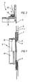
- Figure 1 shows the filter bag sleeve in section.
- Figure 2 shows the flange part enlarged, partly in section.
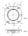
- Figure 3 shows the flange part in plan view.
- Figure 4 shows the flange part in side view.
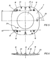
- Figure 5 shows the headboard in plan view.
- Figure 6 shows the head part, partly in section, in a side view.
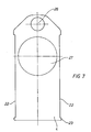
- Figure 7 shows the slide valve in plan view.
- FIG 1 it can be seen that a head part 7 according to Figure 5 and Figure 6 is glued to the outside of the filter bag 6, which in turn can be covered on the outside by a slide 4 according to Figure 7.
- This slide 4 is slidably guided along latching feet 18 on the head part 7, the guide on the other side being formed by a corresponding surface of a flange part 5.
- the flange part 5 and the head part 7 are held together by snap connections.
- the flange part 5 according to FIG. 1 forms an opening 14 through which the dirt is let into the filter bag 6.
- the flange part 5 has a tubular extension, on the inside of which two detents 8 are arranged, distributed around the circumference, with which the flange part 5 is snapped onto an associated groove in the region of the inlet fitting, not shown.
- an O-ring is also arranged in a manner known per se, which lies against the inside of the tubular flange part 5.
- the flange part 5 On the outer circumference, the flange part 5 according to FIG. 2 has a groove 12 in which a plastic bag 10 is held. The mounting is done in that a clamping ring 13 engages in this groove and clamps the plastic bag 10.
- the head part 7 according to FIGS. 5 to 6 consists of a pre-bent part, which should adapt to the shape of the flange part 5 as far as possible in order to ensure that the film slide 4 fits snugly against this leaf-shaped head part 7.
- the pre-bend also makes the necessary dust tightness between the head part 7 and the slide 4 achieved, as well as an inhibiting effect that prevents the slide valve from being accidentally moved.
- the pre-bending also results in a permanent prestress for the snap-in connection of flange part 5 and head part 7.
- the head part defines an inner opening 17 which is substantially aligned with the opening 14 of the flange part 5.
- latching feet 18 are formed on one side of the head part 7.
- latching feet have hook-shaped lugs which engage in associated recesses 19 in the flange part 5 according to FIG. 3.
- a dome 25 is attached, which cooperates with the grip hole 26 of the slide 4. So that in addition to the clamping effect by the pre-bending of the head part 7 accidental and unintentional closing of the slide 4 prevented and the slide 4 of Figure 5 is thus locked in the open position on the head part 7 of Figure 5.
- the entire filter bag sleeve consisting of the head part 7, the flange part 5 and the film slide 4, consists of a plastic material that can be optimally glued to the paper material of the filter bag 6.
- lip seals 9 (FIG. 1, 2) are present, which are arranged on the circumference of the recess in the head part 7 and the flange part 5 and which seal (frictionally) from both sides against the film slide 4.
Landscapes
- Engineering & Computer Science (AREA)
- Mechanical Engineering (AREA)
- Filters For Electric Vacuum Cleaners (AREA)
Description
- Die Erfindung bezieht sich auf eine Filtersackmuffe für einen Schmutzsauger, wobei auf den innenseitigen Stutzen eines Schmutzsaugers in Verbindung mit miteinander fluchtenden Öffnungen ein Papiersack und ein umhüllender Foliensack über staubdicht wirkende Verbindungsteile aufgebracht wird.
- Die Filtersackmuffe nach der Erfindung ist insoweit an einer zweiteilig wirkenden Filtersackanordnung, bestehend aus einem Foliensack und aus einem Papiersack, befestigt und wird von der Innenseite des Schmutzsaugers her auf den von außen wirkenden Einlaß, der in den Innenbereich des Schmutzsaugers in einen Stutzen übergeht, vollständig aufgeschoben.
- Nach dem Stand der Technik war bisher am Filtersack eine einfache, ringförmige Muffe vorgesehen, die konisch ausgeführt war und die auf einem konischen Hals einfach aufgesteckt war. Diese Ausführungsform hatte den Nachteil, daß bei nicht maßgenauen Teilen, wenn z.B. die Filtersackmuffe maßlich Übermaß hatte, keine sichere Befestigung am Einlaßfitting sichergestellt war. Der dritte Nachteil dieser bekannten Muffe war, daß vor dem Abziehen der Filtersackmuffe vom Einlaßfitting die Filtersackmuffe nicht verschlossen werden konnte und wenn in diesem Filtersack gesundheitsgefährlicher Staub oder giftiger Staub eingesogen war, dann konnte beim Abziehen der Muffe vom Einlaß dieser gesundheitsgefährliche Staub austreten und somit die Bedienperson damit beeinträchtigen.
- Der zweite Nachteil dieser kraftschlüssigen Ausführungsform war, daß zum Aufstecken der Muffe hohe Kräfte angewendet werden mußten, um einen sicheren Halt auf dem Stutzen zu gewährleisten. Die Betriebssicherheit war also nicht konstruktionsbedingt, sondern abhängig von der Bedienperson.
- Die Aufgabe der Erfindung liegt deshalb darin, eine Filtersackmuffe der genannten Art so weiterzubilden, daß der Filtersack auf betriebssichere Weise mit dem Einlaßfitting verbunden wird, und außerdem eine Kontamination der Bedienperson ausgeschlossen wird.
- Zur Lösung der gestellten Aufgabe ist die Erfindung durch die technische Lehre des Anspuches 1 gekennzeichnet.
- Ein weiteres wesentliches Merkmal der Erfindung ist, daß in die Filtersackmuffe ein Schieber integriert ist, der als Folienschieber ausgebildet ist. Bevor die Filtersackmuffe vom Einlaßfitting genommen wird, wird der Schieber geschlossen, d.h. er wird seitlich verschoben und rastet in seiner Endstellung noch zusätzlich ein, so daß ein selbsttätiges Öffnen des Folienschiebers nicht mehr möglich ist. Die Filtersackmuffe als solche ist im weiteren so ausgebildet, daß sie einen zusätzlichen Rast auf dem zylindrisch ausgebildeten Teil des Einlaßfittings hat. Dazu sind zusätzliche Rastzungen so ausgebildet, daß sie in eine Nut des Einlaßfittings einrasten. Die Filtersackmuffe wird also an dem Einlaßfitting eingerastet, womit der Vorteil besteht, daß eine formschlüssige und damit auch mechanisch sichere und doch manuell leicht lösbare Verbindung erzielt wird, wobei die Funktion der Abdichtung zwischen Einlaßfitting und Filtersackmuffe von einem zusätzlich, in eine Nut auf dem Einlaßfittingstutzen, eingelegten Dichtring (O-Ring) übernommen wird. Weiterhin ist wesentlich, daß der Folienschieber abgedichtet im Zwischenraum zwischen dem Flanschteil und dem Kopfteil verschiebbar geführt ist. Die Abdichtung erfolgt bevorzugt über Lippendichtungen, die einander gegenüberliegend am Umfang der Ausnehmung im Flansch- und Kopfteil angeordnet sind. Diese Lippendichtungen legen sich von beiden Seiten her an den Folienschieber an und dichten diesen ab.
- Der Folienschieber wird handbetätigt, indem er nach Art eines Folienverschlusses über die öffnung der Filtersackmuffe gezogen wird.
- Im folgenden wird die Erfindung anhand von lediglich einen Ausführungsweg darstellende Zeichnungen näher erläutert. Hierbei gehen aus den Zeichnungen und ihrer Beschreibung weitere wesentliche Merkmale und Vorteile der Erfindung hervor.
- Figur 1 zeigt hierbei die Filtersackmuffe im Schnitt.
- Figur 2 zeigt das Flanschteil vergrößert, teilweise im Schnitt.
- Figur 3 zeigt das Flanschteil in Draufsicht.
- Figur 4 zeigt das Flanschteil in Seitenansicht.
- Figur 5 zeigt das Kopfteil in Draufsicht.
- Figur 6 zeigt das Kopfteil teilweise im Schnitt in Seitenansicht.
- Figur 7 zeigt den Folienschieber in Draufsicht.
- In Figur 1 ist erkennbar, daß auf der Außenseite des Filtersackes 6 ein Kopfteil 7 nach Figur 5 und Figur 6 aufgeklebt ist, welches wiederum an seiner Außenseite von einem Folienschieber 4 nach Figur 7 abdeckbar ist. Dieser Folienschieber 4 ist verschiebbar entlang Rastfüßen 18 auf dem Kopfteil 7 geführt, wobei die Führung auf der anderen Seite durch eine entsprechende Fläche eines Flanschteiles 5 gebildet ist.
- Das Flanschteil 5 und das Kopfteil 7 werden durch Schnappverbindungen zusammengehalten.
- Das Flanschteil 5 nach Figur 1 bildet eine Öffnung 14, durch welche der Schmutz in den Filtersack 6 eingelassen wird.
- Das Flanschteil 5 hat einen rohrförmigen Ansatz, an dem im Innenbereich zwei, am Umfang verteilt angeordnete, Rastnasen 8 angeordnet sind, mit denen das Flanschteil 5 auf eine zugeordnete Nut im Bereich des nicht dargestellten Einlaßfittings aufgeschnappt wird.
- Im Mantelbereich des Einlaßes ist ferner in ansich bekannter Weise ein O-Ring angeordnet, der sich an die Innenseite des rohrförmigen Flanschteils 5 anlegt.
- Am Außenumfang weist das Flanschteil 5 nach Figur 2 eine Nut 12 auf, in welcher ein Kunststoffsack 10 gehalten wird. Die Halterung erfolgt hierbei dadurch, daß in diese Nut ein Spannring 13 eingreift und hierbei den Kunststoffsack 10 verklammert.
- Damit ist es möglich, zusätzlich zu dem in der Regel aus Papier bestehenden Filtersack 6 noch einen Kunststoffsack 10 zu verwenden, der eine staubfreie Entsorgung des Filtersackes 6 gewährleistet.
- Die Verklammerung zwischen dem Flanschteil 5 und dem Kopfteil 7 erfolgt durch entsprechende Rastverbindungen, die anhand der Figuren 3 bis 6 näher beschrieben werden.
- In Figur 4 ist die Seitenansicht des Flanschteils 5 dargestellt, wo eine Rastnase 8 definiert wird, die durch eine entsprechende Freistanzung herausgestellt ist.
- Das Kopfteil 7 gemäss den Figuren 5 bis 6 besteht aus einem vorgebogenen Teil, welches sich möglichst der Formgebung des Flanschteils 5 anpassen soll, um eine satte Anlage des Folienschiebers 4 an diesem blattförmigen Kopfteil 7 zu gewährleisten. Durch die Vorbiegung wird außerdem die notwendige Staubdichtheit zwischen Kopfteil 7 und Folienschieber 4 erreicht, sowie eine Hemmwirkung, die ein versehentliches Verschieben des Folienschiebers verhindert. Durch die Vorbiegung ergibt sich außerdem eine dauerhafte Vorspannung für die Rastverbindung von Flanschteil 5 und Kopfteil 7.
- Das Kopfteil definiert hierbei eine innere Öffnung 17, die mit der Öffnung 14 des Flanschteiles 5 im wesentlichen fluchtet.
- An der einen Seite des Kopfteils 7 sind hierbei Rastfüße 18 angeformt.
- Diese Rastfüße weisen hakenförmige Ansätze auf, die in zugeordnete Ausnehmungen 19 im Flanschteil 5 nach Figur 3 eingreifen.
- Zur Montage sind Fixierzapfen 20 nach Figur 6 vorhanden, die in entsprechende Bohrungen 21 im Flanschteil 5 eingreifen. Die Führung des Folienschiebers 4, der in Figur 7 in Draufsicht gezeigt ist, erfolgt nun so, daß er zwischen den Rastnasen 18 gerade geführt wird, und zwar in Pfeilrichtung 21a. Der Folienschieber 4 liegt also mit seinen seitlichen Kanten 22 an der Innenseite der Rastfüße 18 an. Es ist hierbei ein Anschlag 23 vorhanden, der verhindert, daß der Schieber vollständig aus der Führung zwischen dem Kopfteil 7 und dem Flanschteil 5 herausgezogen werden kann. Diese Anschläge 23 schlagen hierbei an den Rastfüßen 18 nach Figur 5 an. Zwei Verriegelungsnocken 24 auf dem Kopfteil 7 verhindern dann, daß der Folienschieber - wenn er einmal zugezogen ist - wieder aufgezogen werden kann, wodurch gesorgt wird, daß die Anschläge 23 im Zwischenraum zwischen der Nocke 24 und der jeweiligen Rastnase 18 zum Liegen kommen.
- Damit wird ein sicherer Verschluß der Filtersackmuffe bei einem einmal geschlossenen Folienschieber 4 gewährleistet.
- Auf der Oberfläche des Kopfteiles 7 ist eine Kuppe 25 angebracht, die mit dem Griffloch 26 des Folienschiebers 4 zusammenwirkt. Damit wird zusätzlich zu der Klemmwirkung durch die Vorbiegung des Kopfteils 7 ein zufälliges und unbeabsichtigtes Schließen des Folienschiebers 4 verhindert und der Folienschieber 4 nach Figur 5 wird somit in Offenstellung an dem Kopfteil 7 nach Figur 5 verrastet. Das heisst, die Öffnung 27 des Folienschiebers fluchtet in Öffnungsstellung mit der Öffnung 17 des Kopfteiles und ferner mit der Öffnung 14 des Flanschteiles.
- Die gesamte Filtersackmuffe, bestehend aus dem Kopfteil 7, dem Flanschteil 5 und dem Folienschieber 4, besteht aus einem Kunststoffmaterial, das sich optimal mit dem Papiermaterial des Filtersackes 6 verkleben lässt.
- Der Folienschieber 4 ist abgedichtet im Zwischenraum zwischen dem Flanschteil 5 und dem Kopfteil 7 geführt. Hierfür sind Lippendichtungen 9 (Figur 1,2) vorhanden, die am Umfang der Ausnehmung im Kopfteil 7 und Flanschteil 5 angeordnet sind und die sich abdichtend (reibschlüssig) von beiden Seiten her an dem Folienschieber 4 anlegen.
- Durch die gegebene formschlüssige Einrastverbindung der Filtersackmuffe an dem Einlaßfitting wird also ein sicherer Sitz erreicht, der durch eine an sich bekannte Dichtung staubdicht ausgebildet ist. Beim Stand der Technik waren lediglich kraftschlüssige Verbindungen, nämlich konische Steckverbindungen oder Verbindungen über Elastomermembranen, vorhanden, während jetzt nach der Erfindung eine formschlüssige Rastverbindung vorhanden ist. Diese formschlüssige Rastverbindung ist zwar beim gewollten Abnehmen verhältnismässig leicht lösbar, bietet jedoch im Betrieb genügend Sicherheit gegen unbeabsichtigtes Lösen durch Unterdruckkräfte und/oder Zugkräfte durch den befüllten Filtersack. Sie ist außerdem außerordentlich staubdicht und relativ unabhängig von Fertigungstoleranzen, wobei die zusätzliche Dichtung als O-Ring noch für eine zusätzliche Abdichtung sorgt.
-
- 4
- Folienschieber
- 5
- Flanschteil
- 6
- Filtersack
- 7
- Kopfteil
- 8
- Rastnase
- 9
- Lippendichtung
- 10
- Kunststoffsack
- 12
- Nut
- 13
- Spannring
- 14
- Öffnung
- 17
- Öffnung
- 18
- Rastfuß
- 19
- Ausnehmung
- 20
- Fixierzapfen
- 21
- Bohrung
- 22a
- Pfeilrichtung
- 22
- Kanten
- 23
- Anschlag
- 24
- Nocke
- 25
- Kuppe
- 26
- Griffloch
- 27
- Öffnung
Claims (6)
- Filtersackmuffe an einer zweiteiligen Filtersackanordnung, welche auf den innenseitigen Stutzen eines Schmutzsaugers über staubdicht wirkende Verbindungsteile aufgebracht werden kann, die einen Papiersack (6) und einen, diesen umhüllenden Foliensack (10) aufweist, wobei das mit dem Papiersack (6) verbundene, von der Innenseite des Papiersacks (6) auf den Flanschverbund aufrastende, Kopfteil (7) mit einem Flanschteil (5) rastend verbunden ist, welcher mittels eines Spannrings mit dem Foliensack (10) verbunden ist.
- Muffe nach Anspruch 1, dadurch gekennzeichnet, daß zwischen dem Flanschteil (5) und dem Kopfteil (7) ein schmaler Zwischenraum ausgebildet ist, in dem ein Verschlußschieber als Folienschieber (4) zwischen Rastungen angeordnet ist.
- Filtersackmuffe nach Anspruch 2, dadurch gekennzeichnet, daß das Flanschteil eine Rastanordnung nach Art einer Rastnase (8) aufweist.
- Filtersackmuffe nach einem der Ansprüche 1-3, dadurch gekennzeichnet, daß die Funktion der Abdichtung zwischen Einlaßfitting und Filtersackmuffe von einem zusätzlich, in eine Nut auf dem Einlaßfittingstutzen, eingelegten Dichtring, insbesondere O-Ring, übernommen wird.
- Filtermuffe nach Anspruch 2, dadurch gekennzeichnet, daß der als Folienschieber (4) ausgebildete Verschlußschieber abgedichtet in dem Zwischenraum zwischen dem Flanschteil (5) und dem Kopfteil (7) verschiebbar geführt ist.
- Filtermuffe nach Anspruch 5, dadurch gekennzeichnet, daß die Abdichtung des Folienschiebers (4) durch Lippendichtungen (9) erfolgt, die sich beidseitig an dem Folienschieber (4) anlegen und am umlaufenden Rand der Öffnungen im Flansch- (5) und Kopfteil (7) angeordnet sind.
Applications Claiming Priority (2)
| Application Number | Priority Date | Filing Date | Title |
|---|---|---|---|
| DE9204479U | 1992-04-02 | ||
| DE9204479U DE9204479U1 (de) | 1992-04-02 | 1992-04-02 | Filtersackmuffe für einen Schmutzsauger |
Publications (2)
| Publication Number | Publication Date |
|---|---|
| EP0563869A1 EP0563869A1 (de) | 1993-10-06 |
| EP0563869B1 true EP0563869B1 (de) | 1996-12-18 |
Family
ID=6878019
Family Applications (1)
| Application Number | Title | Priority Date | Filing Date |
|---|---|---|---|
| EP93105203A Expired - Lifetime EP0563869B1 (de) | 1992-04-02 | 1993-03-30 | Filtersackmuffe für einen Schmutzsauger |
Country Status (3)
| Country | Link |
|---|---|
| EP (1) | EP0563869B1 (de) |
| AT (1) | ATE146346T1 (de) |
| DE (2) | DE9204479U1 (de) |
Families Citing this family (4)
| Publication number | Priority date | Publication date | Assignee | Title |
|---|---|---|---|---|
| DE19911331C1 (de) * | 1999-03-15 | 2000-05-31 | Hartmut J Schneider | Staubsaugerbeutel |
| SE521544C2 (sv) * | 2002-03-08 | 2003-11-11 | Electrolux Ab | Anordning och förfarande för att samtidigt avskilja och försluta en tubformad bana i en dammsugare |
| DE102018211712A1 (de) * | 2018-07-13 | 2020-01-16 | Festool Gmbh | Verschlusseinrichtung, System, Partikelauffanganordnung und Saugvorrichtung |
| CN111084578A (zh) * | 2019-12-31 | 2020-05-01 | 杰之深(苏州)科技有限公司 | 一种吸尘器尘杯分离结构 |
Family Cites Families (4)
| Publication number | Priority date | Publication date | Assignee | Title |
|---|---|---|---|---|
| NL7115730A (de) * | 1971-11-16 | 1973-05-18 | ||
| NL7900622A (nl) * | 1979-01-26 | 1980-07-29 | Philips Nv | Stofzuiger. |
| EP0269592A3 (de) * | 1986-11-28 | 1988-10-19 | Aktiebolaget Electrolux | Vielschicht-Aussen- und Innenstaubsackfiltervorrichtung für einen Staubsauger |
| DE9114068U1 (de) * | 1991-11-11 | 1992-02-06 | Ringler, Bernhard, 7076 Waldstetten | Sammelbehälter |
-
1992
- 1992-04-02 DE DE9204479U patent/DE9204479U1/de not_active Expired - Lifetime
-
1993
- 1993-03-30 AT AT93105203T patent/ATE146346T1/de not_active IP Right Cessation
- 1993-03-30 DE DE59304776T patent/DE59304776D1/de not_active Expired - Fee Related
- 1993-03-30 EP EP93105203A patent/EP0563869B1/de not_active Expired - Lifetime
Also Published As
| Publication number | Publication date |
|---|---|
| DE9204479U1 (de) | 1993-05-19 |
| DE59304776D1 (de) | 1997-01-30 |
| EP0563869A1 (de) | 1993-10-06 |
| ATE146346T1 (de) | 1997-01-15 |
Similar Documents
| Publication | Publication Date | Title |
|---|---|---|
| DE69602594T2 (de) | Gehäuse für ein gasventil und verfahren zum verbinden von zwei gehäuseteilen | |
| DE2828100C2 (de) | Kindersicherer Verschluß | |
| DE10127823C1 (de) | Verschluss für eine Medikamentenflasche sowie Verfahren zu dessen Herstellung | |
| EP0421410A2 (de) | Behälter aus Kunststoff für die Entsorgung von medizinischen Einweg-Gegenständen und -Geräten | |
| DE3833799C2 (de) | Staubsauger mit einem Filter | |
| DE3538589A1 (de) | Oelfilter zum reinigen von schmieroel | |
| EP0316868A1 (de) | Verschluss zum Verschliessen von Kunststoffbeuteln und dergleichen | |
| EP1000632A2 (de) | Verschlusselement | |
| DE3622501A1 (de) | Rastvorrichtung zur versiegelung | |
| EP3749137B1 (de) | Verschluss für eine trinkflasche | |
| DE9016939U1 (de) | Filtereinrichtung für einen Staubsauger | |
| EP0021406A1 (de) | Filmkassette mit einem Fenster zum Einbelichten von Daten | |
| DE20005448U1 (de) | Halteplatte eines Staubsauger-Filterbeutels | |
| EP0563869A1 (de) | Filtersackmuffe für einen Schmutzsauger | |
| WO1991007794A1 (de) | Strahlwassergeschütztes anschlussgehäuse für elektrische verbraucher | |
| EP0803225B1 (de) | Anordnung zum lösbaren Verbinden eines Saugstutzens mit der Saugöffnung eines Staubsaugers | |
| EP0655217A1 (de) | Elektro-Staubsauger mit einer Aufnahmekammer für einen Staubbeutel | |
| DE19651027A1 (de) | Vorrichtung zur Bodenreinigung | |
| DE69300779T2 (de) | Verbesserungen an Rohrverbindungen. | |
| EP0089685A2 (de) | Chemikalienbehälter | |
| DE8907662U1 (de) | Verpackungsbehälter | |
| EP0153999B1 (de) | Entlüftungsventil insbesondere zum Entlüften von Heizsystemen | |
| EP3749161B1 (de) | Verschlusseinrichtung, system, partikelauffanganordnung und saugvorrichtung | |
| EP1431113B1 (de) | Formteil zur Halterung und Versteifung eines laschenförmigen Ausschnittteils in einem flächigen Gut | |
| DE8804303U1 (de) | Becherförmiger Behälter |
Legal Events
| Date | Code | Title | Description |
|---|---|---|---|
| PUAI | Public reference made under article 153(3) epc to a published international application that has entered the european phase |
Free format text: ORIGINAL CODE: 0009012 |
|
| AK | Designated contracting states |
Kind code of ref document: A1 Designated state(s): AT BE CH DE DK ES FR GB GR IE IT LI LU MC NL PT SE |
|
| 17P | Request for examination filed |
Effective date: 19940125 |
|
| 17Q | First examination report despatched |
Effective date: 19950314 |
|
| GRAG | Despatch of communication of intention to grant |
Free format text: ORIGINAL CODE: EPIDOS AGRA |
|
| GRAH | Despatch of communication of intention to grant a patent |
Free format text: ORIGINAL CODE: EPIDOS IGRA |
|
| GRAH | Despatch of communication of intention to grant a patent |
Free format text: ORIGINAL CODE: EPIDOS IGRA |
|
| GRAA | (expected) grant |
Free format text: ORIGINAL CODE: 0009210 |
|
| AK | Designated contracting states |
Kind code of ref document: B1 Designated state(s): AT BE CH DE DK ES FR GB GR IE IT LI LU MC NL PT SE |
|
| PG25 | Lapsed in a contracting state [announced via postgrant information from national office to epo] |
Ref country code: GR Free format text: LAPSE BECAUSE OF FAILURE TO SUBMIT A TRANSLATION OF THE DESCRIPTION OR TO PAY THE FEE WITHIN THE PRESCRIBED TIME-LIMIT Effective date: 19961218 Ref country code: ES Free format text: THE PATENT HAS BEEN ANNULLED BY A DECISION OF A NATIONAL AUTHORITY Effective date: 19961218 Ref country code: DK Effective date: 19961218 |
|
| REF | Corresponds to: |
Ref document number: 146346 Country of ref document: AT Date of ref document: 19970115 Kind code of ref document: T |
|
| REF | Corresponds to: |
Ref document number: 59304776 Country of ref document: DE Date of ref document: 19970130 |
|
| REG | Reference to a national code |
Ref country code: IE Ref legal event code: FG4D Free format text: 71063 |
|
| REG | Reference to a national code |
Ref country code: CH Ref legal event code: NV Representative=s name: PATENTANWALTSBUERO JEAN HUNZIKER |
|
| ITF | It: translation for a ep patent filed | ||
| PG25 | Lapsed in a contracting state [announced via postgrant information from national office to epo] |
Ref country code: SE Effective date: 19970318 Ref country code: PT Effective date: 19970318 |
|
| PG25 | Lapsed in a contracting state [announced via postgrant information from national office to epo] |
Ref country code: LU Free format text: LAPSE BECAUSE OF NON-PAYMENT OF DUE FEES Effective date: 19970331 Ref country code: BE Effective date: 19970331 |
|
| ET | Fr: translation filed | ||
| GBT | Gb: translation of ep patent filed (gb section 77(6)(a)/1977) |
Effective date: 19970319 |
|
| PG25 | Lapsed in a contracting state [announced via postgrant information from national office to epo] |
Ref country code: MC Effective date: 19970930 |
|
| PLBE | No opposition filed within time limit |
Free format text: ORIGINAL CODE: 0009261 |
|
| 26N | No opposition filed | ||
| PGFP | Annual fee paid to national office [announced via postgrant information from national office to epo] |
Ref country code: CH Payment date: 20000308 Year of fee payment: 8 |
|
| PGFP | Annual fee paid to national office [announced via postgrant information from national office to epo] |
Ref country code: IE Payment date: 20000316 Year of fee payment: 8 |
|
| PGFP | Annual fee paid to national office [announced via postgrant information from national office to epo] |
Ref country code: NL Payment date: 20000329 Year of fee payment: 8 Ref country code: FR Payment date: 20000329 Year of fee payment: 8 |
|
| PGFP | Annual fee paid to national office [announced via postgrant information from national office to epo] |
Ref country code: AT Payment date: 20000331 Year of fee payment: 8 |
|
| PG25 | Lapsed in a contracting state [announced via postgrant information from national office to epo] |
Ref country code: IE Free format text: LAPSE BECAUSE OF NON-PAYMENT OF DUE FEES Effective date: 20010330 Ref country code: AT Free format text: LAPSE BECAUSE OF NON-PAYMENT OF DUE FEES Effective date: 20010330 |
|
| PG25 | Lapsed in a contracting state [announced via postgrant information from national office to epo] |
Ref country code: LI Free format text: LAPSE BECAUSE OF NON-PAYMENT OF DUE FEES Effective date: 20010331 Ref country code: CH Free format text: LAPSE BECAUSE OF NON-PAYMENT OF DUE FEES Effective date: 20010331 |
|
| PG25 | Lapsed in a contracting state [announced via postgrant information from national office to epo] |
Ref country code: NL Free format text: LAPSE BECAUSE OF NON-PAYMENT OF DUE FEES Effective date: 20011001 |
|
| REG | Reference to a national code |
Ref country code: CH Ref legal event code: PL |
|
| PG25 | Lapsed in a contracting state [announced via postgrant information from national office to epo] |
Ref country code: FR Free format text: LAPSE BECAUSE OF NON-PAYMENT OF DUE FEES Effective date: 20011130 |
|
| NLV4 | Nl: lapsed or anulled due to non-payment of the annual fee |
Effective date: 20011001 |
|
| REG | Reference to a national code |
Ref country code: FR Ref legal event code: ST |
|
| REG | Reference to a national code |
Ref country code: GB Ref legal event code: IF02 |
|
| REG | Reference to a national code |
Ref country code: IE Ref legal event code: MM4A |
|
| PGFP | Annual fee paid to national office [announced via postgrant information from national office to epo] |
Ref country code: GB Payment date: 20020304 Year of fee payment: 10 |
|
| PG25 | Lapsed in a contracting state [announced via postgrant information from national office to epo] |
Ref country code: GB Free format text: LAPSE BECAUSE OF NON-PAYMENT OF DUE FEES Effective date: 20030330 |
|
| GBPC | Gb: european patent ceased through non-payment of renewal fee |
Effective date: 20030330 |
|
| PGFP | Annual fee paid to national office [announced via postgrant information from national office to epo] |
Ref country code: DE Payment date: 20040216 Year of fee payment: 12 |
|
| PG25 | Lapsed in a contracting state [announced via postgrant information from national office to epo] |
Ref country code: IT Free format text: LAPSE BECAUSE OF NON-PAYMENT OF DUE FEES;WARNING: LAPSES OF ITALIAN PATENTS WITH EFFECTIVE DATE BEFORE 2007 MAY HAVE OCCURRED AT ANY TIME BEFORE 2007. THE CORRECT EFFECTIVE DATE MAY BE DIFFERENT FROM THE ONE RECORDED. Effective date: 20050330 |
|
| PG25 | Lapsed in a contracting state [announced via postgrant information from national office to epo] |
Ref country code: DE Free format text: LAPSE BECAUSE OF NON-PAYMENT OF DUE FEES Effective date: 20051001 |