EP0563459B1 - Schnurlose Wechselsprechanlage - Google Patents
Schnurlose Wechselsprechanlage Download PDFInfo
- Publication number
- EP0563459B1 EP0563459B1 EP92200960A EP92200960A EP0563459B1 EP 0563459 B1 EP0563459 B1 EP 0563459B1 EP 92200960 A EP92200960 A EP 92200960A EP 92200960 A EP92200960 A EP 92200960A EP 0563459 B1 EP0563459 B1 EP 0563459B1
- Authority
- EP
- European Patent Office
- Prior art keywords
- circuit
- battery
- transceiver
- wireless intercom
- output
- Prior art date
- Legal status (The legal status is an assumption and is not a legal conclusion. Google has not performed a legal analysis and makes no representation as to the accuracy of the status listed.)
- Expired - Lifetime
Links
- 239000003990 capacitor Substances 0.000 description 9
- 238000010586 diagram Methods 0.000 description 5
- 230000005236 sound signal Effects 0.000 description 5
- 230000010354 integration Effects 0.000 description 2
- 230000005540 biological transmission Effects 0.000 description 1
- 238000010276 construction Methods 0.000 description 1
- 230000007547 defect Effects 0.000 description 1
- 238000009434 installation Methods 0.000 description 1
- 238000012986 modification Methods 0.000 description 1
- 230000004048 modification Effects 0.000 description 1
Images


Classifications
-
- H—ELECTRICITY
- H04—ELECTRIC COMMUNICATION TECHNIQUE
- H04B—TRANSMISSION
- H04B1/00—Details of transmission systems, not covered by a single one of groups H04B3/00 - H04B13/00; Details of transmission systems not characterised by the medium used for transmission
- H04B1/38—Transceivers, i.e. devices in which transmitter and receiver form a structural unit and in which at least one part is used for functions of transmitting and receiving
- H04B1/40—Circuits
- H04B1/44—Transmit/receive switching
- H04B1/46—Transmit/receive switching by voice-frequency signals; by pilot signals
Definitions
- the present invention relates to a voice-controlled speaker microphone of a wireless intercom, especially to a voice-controlled speaker microphone of a wireless intercom having a self-feed function in order to achieve the objective to avoid the need for external power and to avoid fast consumption of batteries.
- the present invention is directed to a voice-controlled speaker microphone of a wireless intercom.
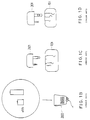
- a conventional wireless intercom is composed of a transceiver 100, a sound controlled speaker microphone 200 which is connecting to the transceiver 100 by inserting a plug 201 connecting with speaker microphone 200 into a receptacle 101 on the transceiver 100.
- the kinds of the design and disadvantages of the above mentioned voice-controlled are as follows:
- the present invention is firstly to provide a voice controlled speaker microphone of wireless intercom, it comprises a specified voice controlled circuit, by merely using the bias flowing through the manual switch (PTT) and condenser microphones, it can be used as electric energy needed by the voice controlled circuit of speaker microphone of the present invention, it then does not have the trouble of replacing batteries frequently, its economical effects are highly improved.
- PTT manual switch
- condenser microphones by merely using the bias flowing through the manual switch (PTT) and condenser microphones, it can be used as electric energy needed by the voice controlled circuit of speaker microphone of the present invention, it then does not have the trouble of replacing batteries frequently, its economical effects are highly improved.
- the speaker microphone of wireless intercom of the present invention can be used without the necessity for the transceiver to supply electric source for used as the electric energy required by voice controlled circuit. Then the input/output receptacle of transceiver is not necessary to consider the output of electric source. The special design is not necessary, if the pins of plug is able to insert into the receptacle, any kinds of transceiver can be replaced for uses, this is another object of the present invention.
- its voice controlled speaker microphone is able to obtain receiving & sending signals to control the receiving & sending conditions of voice controlled circuit.
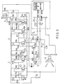
- Fig. 2 is a block diagram of the whole assembly of the present invention. It is clearly shown in said figure that the wireless intercom transceiver according to the invention mainly comprises a first condenser mic 81, an amplifying circuit 1, an integrating circuit 2, a switching characteristic booster circuit 3, a transistor switching circuit 4, a second condenser mic 82, a voltage multiplying rectifying circuit 5 , a transceiver control circuit 7 and a speaker 9, wherein the first condenser mic 81 is connected with the amplifying circuit 1 thereby the audio signal is amplified to the degree of ready for integration; the amplifying circuit 1 is output to the integrating circuit 2 for the purpose of integrating the audio signal output from the amplifying circuit to a hi-low signal; the output of which is in turn connected to a switching characteristic booster circuit 3 which may boosters the switching characteristics of the hi-low signal into a square wave; the latter is in turn via a resistor K10, a condenser C5 connected to the transistor switching circuit 4 which is output to
- the amplifying circuit 1 is composed of transistors Q7, Q8 in combined with capacitors C1, C2, C3 and resistors R1, R2, R17, R18, R19;
- the intergrating circuit 2 is composed of transistors Q1, Q2, and resistors R3, R4, R5, R6, R7 in combination with condenser C4 as will as a switch S2;
- the switching characteristic booster circuit 3 is mainly composed of transistors Q3, Q4 and resistors R8, R9;
- the switching circuit 4 is consisted of a transistor Q5, a resistor R20 and a capacitor C6;
- the voltage multipling rectifying circuit 5 is composed of a pair of diodes D1 and D2;
- the transceiver control circuit 7 consists of a transistor Q6, resistors R11, R12 and a condenser C7; additionally, which is provided with a diode D3 to prevent flow back through the transistor Q6.
- the audio signal received by the condenser mic 81 is amplified by the transistors Q7, Q8 of the amplifying circuit 1 to give a one hundred times of gain (the waveform thereof is as shown in Fig. 4A) and then sent to the transistor Q1 of the integrating circuit 2. Normally, said transistor Q1 is kept in saturation. While receiving, the transistor Q1 gets the pulse (the waveform thereof is as shown is Fig. 4B) of the audio signal by the collector thereof and sents to the transistor Q2, following integration to obtain a hi-low potential (its waveform is as shown in Fig.
- the hi-low potential's waveform is smoothed into a square wave (the waveform thereof is as shown in Fig. 4D) by means of the switching characteristic booster circuit 3 in order to drive the transistor Q5 in the switching circuit 4 to achieve the objective transmission.
- the second condenser mic 82 is connected in parallel with the resistor R16 and then to the microphone input node of the transceiver or wireless intercom main set 6.
- the bias current of the transceiver flows through the second condenser mic 82, the resistor R16 in parallel, and the transistor Q5, thereafter is filtered while passing through the capacitor C5 and then via R10 charging to the battery B to give a charging current I1 of 0.6mA to 1.0mA.
- the speaker 9 is driven by use of the couple capacitor output from the OTL amplifier inside of the transceiver 6 and the capacitor C8 connected in serial with the speaker 9 in the circuit of the invention.
- the divided voltage is taken as a DC level.
- the DC level is maintained through multiplying the audio signal by the diodes D1, D2 in the voltage multiplying rectifying circuit 5.
- the DC level via the resistor R13 is integrated by the capacitor C7 and then applied to the transistor Q6 of the transceiver control circuit 7 to control the base of the transistor Q2 in the integrating circuit 2 in such a manner that the audio control signal can be turned off upon receiving to make the transceiving smooth.
- This DC level passing through the diode D3 is further filtered by the resistor R15 and the capacitor C5 and charging to the battery via the resistor R10 to give a charging current I2 of 1mA to 30mA.
- the resistors R14, R15 have such a limitation effect that the voltage multiplying rectifying circuit 5 will not effect the receiving quality.
- the supplier current I1 and I2 provides to and is used by the voice-controllable transceiver of the invention (the working current is 0.3mA ), then the transceiver claimed has a self-feed function and no external power source is required. As shown is Fig.5, it is not necessary for the transceiver 6 to provide an electric source as the energy required by its sound controlled circuit.
- the input/output receptacle 11 of transceiver 6 then is not necessary to consider the output of electric sound, its special design is not necessary, if the pins of plug is able to insert into the receptacle, any kinds of wireless intercom transceiver manufactured by different companies can be replaced for uses.
- the wireless intercom of the present invention can really exert the effects of external powerless and self-feed and also elliminate the drawbacks such as, e.g. external power source required and frequent battery replacement of the conventional ones.
Landscapes
- Engineering & Computer Science (AREA)
- Computer Networks & Wireless Communication (AREA)
- Signal Processing (AREA)
- Transceivers (AREA)
- Interconnected Communication Systems, Intercoms, And Interphones (AREA)
Claims (1)
- Schnurlose Wechselsprechanlage mit einem schnurlosen Wechselsprechanlagen-Hauptapparat (6) und einer Sprachsteuerungsschaltung, wobei die genannte Sprachsteuerungsschaltung folgendes umfaßt:ein erstes Kondensatormikrophon (81);eine Verstärkungsschaltung (1), die mit dem ersten Kondensatormikrophon (81) verbunden ist;eine integrierte Schaltung (2), die mit einem Ausgangsknotenpunkt der Verstärkungsschaltung (1) verbunden ist;eine Zusatzschaltung (3) mit Schaltverhalten, die mit einem Ausgangsknotenpunkt der integrierten Schaltung (2) verbunden ist;ein Transistorschaltnetz (4), das mit einem Ausgangsknotenpunkt der ersten Zusatzschaltung (3) mit Schaltverhalten verbunden ist;ein zweites Kondensatormikrophon (82), das mit einem Ausgangsknotenpunkt des genannten ersten Transistorschaltnetzes (4) verbunden ist; undeine Spannungsvervielfacher-Gleichrichterschaltung (5), die mit dem genannten Ausgangsknotenpunkt der integrierten Schaltung (2) verbunden ist und einen Eingangsknotenpunkt aufweist, der mit einem Spannungsausgang des genannten Hauptgerätes (6) verbunden ist;eine Batterie (B), die mit Speisestrom für die Sprachsteuerungsschaltung verbunden ist;einen Lautsprecher (9), der über den genannten Eingangsknotenpunkt der Gleichrichterschaltung (5) mit dem genannten Treiberspannungsausgang des genannten Hauptgeräts (6) verbunden ist;ein Mittel zum Anlegen einer KondensatormikrophonRuhespannung von dem Hauptgerät (6) an das zweite Mikrophon (82) und an die Batterie (B), um der Batterie (B) einen Ladestrom zuzuführen, und ein Mittel zum Anlegen einer Treiberspannung an den Lautsprecher (9) und an die Batterie (B), um der Batterie (B) einen Ladestrom zuzuführen, so daß sich eine externe Stromversorgung und ein häufiges Auswechseln der Batterie (B) erübrigen.
Priority Applications (2)
| Application Number | Priority Date | Filing Date | Title |
|---|---|---|---|
| AT92200960T ATE159841T1 (de) | 1992-04-03 | 1992-04-03 | Schnurlose wechselsprechanlage |
| DE69222930T DE69222930D1 (de) | 1992-04-03 | 1992-04-03 | Schnurlose Wechselsprechanlage |
Applications Claiming Priority (1)
| Application Number | Priority Date | Filing Date | Title |
|---|---|---|---|
| US07/695,998 US5239687A (en) | 1991-05-06 | 1991-05-06 | Wireless intercom having a transceiver in which a bias current for the condenser microphone and the driving current for the speaker are used to charge a battery during transmission and reception, respectively |
Publications (2)
| Publication Number | Publication Date |
|---|---|
| EP0563459A1 EP0563459A1 (de) | 1993-10-06 |
| EP0563459B1 true EP0563459B1 (de) | 1997-10-29 |
Family
ID=24795303
Family Applications (1)
| Application Number | Title | Priority Date | Filing Date |
|---|---|---|---|
| EP92200960A Expired - Lifetime EP0563459B1 (de) | 1991-05-06 | 1992-04-03 | Schnurlose Wechselsprechanlage |
Country Status (2)
| Country | Link |
|---|---|
| US (1) | US5239687A (de) |
| EP (1) | EP0563459B1 (de) |
Families Citing this family (40)
| Publication number | Priority date | Publication date | Assignee | Title |
|---|---|---|---|---|
| JP2504516Y2 (ja) | 1992-04-17 | 1996-07-10 | 世中 陳 | 無線通信装置 |
| AU9104598A (en) * | 1997-08-14 | 1999-03-08 | Ericsson Inc. | Handset for half-duplex communications through a cellular terminal |
| US6104923A (en) * | 1997-10-03 | 2000-08-15 | Karen Kite | Remote operational screener |
| US7515896B1 (en) | 1998-10-21 | 2009-04-07 | Parkervision, Inc. | Method and system for down-converting an electromagnetic signal, and transforms for same, and aperture relationships |
| US6061551A (en) | 1998-10-21 | 2000-05-09 | Parkervision, Inc. | Method and system for down-converting electromagnetic signals |
| US7236754B2 (en) | 1999-08-23 | 2007-06-26 | Parkervision, Inc. | Method and system for frequency up-conversion |
| US6813485B2 (en) * | 1998-10-21 | 2004-11-02 | Parkervision, Inc. | Method and system for down-converting and up-converting an electromagnetic signal, and transforms for same |
| US6542722B1 (en) | 1998-10-21 | 2003-04-01 | Parkervision, Inc. | Method and system for frequency up-conversion with variety of transmitter configurations |
| US6370371B1 (en) | 1998-10-21 | 2002-04-09 | Parkervision, Inc. | Applications of universal frequency translation |
| US7321735B1 (en) | 1998-10-21 | 2008-01-22 | Parkervision, Inc. | Optical down-converter using universal frequency translation technology |
| US7039372B1 (en) | 1998-10-21 | 2006-05-02 | Parkervision, Inc. | Method and system for frequency up-conversion with modulation embodiments |
| US6879817B1 (en) | 1999-04-16 | 2005-04-12 | Parkervision, Inc. | DC offset, re-radiation, and I/Q solutions using universal frequency translation technology |
| US6853690B1 (en) | 1999-04-16 | 2005-02-08 | Parkervision, Inc. | Method, system and apparatus for balanced frequency up-conversion of a baseband signal and 4-phase receiver and transceiver embodiments |
| US6873836B1 (en) | 1999-03-03 | 2005-03-29 | Parkervision, Inc. | Universal platform module and methods and apparatuses relating thereto enabled by universal frequency translation technology |
| US7110435B1 (en) * | 1999-03-15 | 2006-09-19 | Parkervision, Inc. | Spread spectrum applications of universal frequency translation |
| US7110444B1 (en) | 1999-08-04 | 2006-09-19 | Parkervision, Inc. | Wireless local area network (WLAN) using universal frequency translation technology including multi-phase embodiments and circuit implementations |
| US7065162B1 (en) | 1999-04-16 | 2006-06-20 | Parkervision, Inc. | Method and system for down-converting an electromagnetic signal, and transforms for same |
| US7693230B2 (en) | 1999-04-16 | 2010-04-06 | Parkervision, Inc. | Apparatus and method of differential IQ frequency up-conversion |
| US8295406B1 (en) | 1999-08-04 | 2012-10-23 | Parkervision, Inc. | Universal platform module for a plurality of communication protocols |
| US7082171B1 (en) | 1999-11-24 | 2006-07-25 | Parkervision, Inc. | Phase shifting applications of universal frequency translation |
| DE29921758U1 (de) * | 1999-12-10 | 2000-02-24 | Wun, Yien Chen, Chungho, Taipeh | Sprachgesteuerte Mundmikrofoneinheit |
| US7010286B2 (en) | 2000-04-14 | 2006-03-07 | Parkervision, Inc. | Apparatus, system, and method for down-converting and up-converting electromagnetic signals |
| US7554508B2 (en) | 2000-06-09 | 2009-06-30 | Parker Vision, Inc. | Phased array antenna applications on universal frequency translation |
| US7454453B2 (en) | 2000-11-14 | 2008-11-18 | Parkervision, Inc. | Methods, systems, and computer program products for parallel correlation and applications thereof |
| US7010559B2 (en) * | 2000-11-14 | 2006-03-07 | Parkervision, Inc. | Method and apparatus for a parallel correlator and applications thereof |
| US7609027B2 (en) | 2001-11-09 | 2009-10-27 | Milwaukee Electric Tool Corporation | Electrical component, audio component, or electrical combination having a selectively connectable battery charger |
| US7072427B2 (en) | 2001-11-09 | 2006-07-04 | Parkervision, Inc. | Method and apparatus for reducing DC offsets in a communication system |
| CA2411303A1 (en) | 2001-11-09 | 2003-05-09 | Milwaukee Electric Tool Corporation | Battery charger |
| US7321640B2 (en) | 2002-06-07 | 2008-01-22 | Parkervision, Inc. | Active polyphase inverter filter for quadrature signal generation |
| US7460584B2 (en) | 2002-07-18 | 2008-12-02 | Parkervision, Inc. | Networking methods and systems |
| US7379883B2 (en) | 2002-07-18 | 2008-05-27 | Parkervision, Inc. | Networking methods and systems |
| US7835534B2 (en) | 2003-10-14 | 2010-11-16 | Robert Bosch Gmbh | Battery charging jobsite lunchbox |
| US8604752B2 (en) | 2003-10-14 | 2013-12-10 | Robert Bosch Gmbh | Portable battery charging and audio unit |
| US20060279405A1 (en) * | 2005-05-17 | 2006-12-14 | Erickson Randall T | Wireless system for alerting hearing-impaired person |
| US7741809B2 (en) | 2006-01-06 | 2010-06-22 | Milwaukee Electric Tool Corporation | Electrical component including a battery receptacle for including a battery |
| US7847658B2 (en) * | 2008-06-04 | 2010-12-07 | Alcatel-Lucent Usa Inc. | Light-weight low-thermal-expansion polymer foam for radiofrequency filtering applications |
| US8222641B2 (en) * | 2009-04-29 | 2012-07-17 | Bose Corporation | Intercom headset connection and disconnection responses |
| WO2012129193A1 (en) | 2011-03-22 | 2012-09-27 | Advanced Electroacoustics Private Limited | A communications apparatus |
| US9351060B2 (en) | 2014-02-14 | 2016-05-24 | Sonic Blocks, Inc. | Modular quick-connect A/V system and methods thereof |
| JP2019118149A (ja) * | 2019-04-17 | 2019-07-18 | 幹開発株式会社 | 通話ユニット、及び通話システム |
Family Cites Families (8)
| Publication number | Priority date | Publication date | Assignee | Title |
|---|---|---|---|---|
| US3980996A (en) * | 1973-09-12 | 1976-09-14 | Myron Greenspan | Self-sustaining alarm transmitter device |
| DE2641660A1 (de) * | 1976-09-16 | 1978-03-23 | Bosch Gmbh Robert | Sprechfunk-einrichtung mit einem funksende- und -empfangsgeraet |
| US4178548A (en) * | 1976-10-04 | 1979-12-11 | Geraldine E. Thompson | Voice actuated mobile radio |
| DE2806778C2 (de) * | 1978-02-17 | 1980-04-17 | Electrolert, Inc., Troy, Ohio (V.St.A.) | Mikrophonverstärker |
| GB2027566A (en) * | 1978-08-01 | 1980-02-20 | Hung Nien Electronics Ltd | Automatic intercom |
| US4426733A (en) * | 1982-01-28 | 1984-01-17 | General Electric Company | Voice-controlled operator-interacting radio transceiver |
| US4673861A (en) * | 1986-04-03 | 1987-06-16 | General Electric Company | Battery charger/remote control for portable radio devices |
| US4684870A (en) * | 1986-04-09 | 1987-08-04 | Uniden Corp. Of America | Transceiver battery charging apparatus and method |
-
1991
- 1991-05-06 US US07/695,998 patent/US5239687A/en not_active Expired - Fee Related
-
1992
- 1992-04-03 EP EP92200960A patent/EP0563459B1/de not_active Expired - Lifetime
Also Published As
| Publication number | Publication date |
|---|---|
| EP0563459A1 (de) | 1993-10-06 |
| US5239687A (en) | 1993-08-24 |
Similar Documents
| Publication | Publication Date | Title |
|---|---|---|
| EP0563459B1 (de) | Schnurlose Wechselsprechanlage | |
| US4304969A (en) | Power circuit for loudspeaker telephone | |
| KR890004531A (ko) | 송신기 회로, 전압-전류변환기 회로 및 전류 증폭기 회로 | |
| US4315109A (en) | Electronic ring sounder for a speaker telephone | |
| US5193107A (en) | Speakerphone test set | |
| US4857884A (en) | Paging system | |
| CA1057843A (en) | High power remote control ultrasonic transmitter | |
| US3461240A (en) | Amplifier with two separate channels | |
| JP2504516Y2 (ja) | 無線通信装置 | |
| US3763326A (en) | Telephone audio signalling arrangement | |
| JPS584856B2 (ja) | 伝送回路装置 | |
| KR910001680B1 (ko) | 키폰 시스템에 있어서 도어폰 인터페이스회로 | |
| WO1988006386A1 (en) | Telephone network coupler | |
| JPH046281Y2 (de) | ||
| CN2126752Y (zh) | 一种无线电对讲机的声控收发话器 | |
| JPS6336757Y2 (de) | ||
| US5963095A (en) | Amplifier circuit, a transmitter and a wireless telephone | |
| JPS60128762A (ja) | 電話機回路 | |
| JPS62227249A (ja) | ドアホン回路 | |
| JPH0413690Y2 (de) | ||
| JP3078292B2 (ja) | 通話電流供給方式 | |
| CA1126170A (en) | Circuit for imposing a d.c. level on an a.c. signal | |
| JPS62159046U (de) | ||
| JPH0661917A (ja) | 電話装置 | |
| JPH0683306B2 (ja) | 電話機用増幅回路 |
Legal Events
| Date | Code | Title | Description |
|---|---|---|---|
| PUAI | Public reference made under article 153(3) epc to a published international application that has entered the european phase |
Free format text: ORIGINAL CODE: 0009012 |
|
| AK | Designated contracting states |
Kind code of ref document: A1 Designated state(s): AT BE CH DE DK ES FR GB GR IT LI LU MC NL PT SE |
|
| 17P | Request for examination filed |
Effective date: 19931203 |
|
| 17Q | First examination report despatched |
Effective date: 19951130 |
|
| GRAG | Despatch of communication of intention to grant |
Free format text: ORIGINAL CODE: EPIDOS AGRA |
|
| GRAH | Despatch of communication of intention to grant a patent |
Free format text: ORIGINAL CODE: EPIDOS IGRA |
|
| GRAH | Despatch of communication of intention to grant a patent |
Free format text: ORIGINAL CODE: EPIDOS IGRA |
|
| GRAA | (expected) grant |
Free format text: ORIGINAL CODE: 0009210 |
|
| AK | Designated contracting states |
Kind code of ref document: B1 Designated state(s): AT BE CH DE DK ES FR GB GR IT LI LU MC NL PT SE |
|
| PG25 | Lapsed in a contracting state [announced via postgrant information from national office to epo] |
Ref country code: IT Free format text: LAPSE BECAUSE OF FAILURE TO SUBMIT A TRANSLATION OF THE DESCRIPTION OR TO PAY THE FEE WITHIN THE PRESCRIBED TIME-LIMIT;WARNING: LAPSES OF ITALIAN PATENTS WITH EFFECTIVE DATE BEFORE 2007 MAY HAVE OCCURRED AT ANY TIME BEFORE 2007. THE CORRECT EFFECTIVE DATE MAY BE DIFFERENT FROM THE ONE RECORDED. Effective date: 19971029 Ref country code: AT Free format text: LAPSE BECAUSE OF FAILURE TO SUBMIT A TRANSLATION OF THE DESCRIPTION OR TO PAY THE FEE WITHIN THE PRESCRIBED TIME-LIMIT Effective date: 19971029 Ref country code: GR Free format text: LAPSE BECAUSE OF FAILURE TO SUBMIT A TRANSLATION OF THE DESCRIPTION OR TO PAY THE FEE WITHIN THE PRESCRIBED TIME-LIMIT Effective date: 19971029 Ref country code: CH Free format text: LAPSE BECAUSE OF FAILURE TO SUBMIT A TRANSLATION OF THE DESCRIPTION OR TO PAY THE FEE WITHIN THE PRESCRIBED TIME-LIMIT Effective date: 19971029 Ref country code: LI Free format text: LAPSE BECAUSE OF FAILURE TO SUBMIT A TRANSLATION OF THE DESCRIPTION OR TO PAY THE FEE WITHIN THE PRESCRIBED TIME-LIMIT Effective date: 19971029 Ref country code: DK Free format text: LAPSE BECAUSE OF NON-PAYMENT OF DUE FEES Effective date: 19971029 Ref country code: ES Free format text: THE PATENT HAS BEEN ANNULLED BY A DECISION OF A NATIONAL AUTHORITY Effective date: 19971029 Ref country code: FR Free format text: LAPSE BECAUSE OF FAILURE TO SUBMIT A TRANSLATION OF THE DESCRIPTION OR TO PAY THE FEE WITHIN THE PRESCRIBED TIME-LIMIT Effective date: 19971029 Ref country code: BE Free format text: LAPSE BECAUSE OF FAILURE TO SUBMIT A TRANSLATION OF THE DESCRIPTION OR TO PAY THE FEE WITHIN THE PRESCRIBED TIME-LIMIT Effective date: 19971029 Ref country code: NL Free format text: LAPSE BECAUSE OF FAILURE TO SUBMIT A TRANSLATION OF THE DESCRIPTION OR TO PAY THE FEE WITHIN THE PRESCRIBED TIME-LIMIT Effective date: 19971029 |
|
| REF | Corresponds to: |
Ref document number: 159841 Country of ref document: AT Date of ref document: 19971115 Kind code of ref document: T |
|
| REG | Reference to a national code |
Ref country code: CH Ref legal event code: EP |
|
| REF | Corresponds to: |
Ref document number: 69222930 Country of ref document: DE Date of ref document: 19971204 |
|
| PG25 | Lapsed in a contracting state [announced via postgrant information from national office to epo] |
Ref country code: PT Free format text: LAPSE BECAUSE OF FAILURE TO SUBMIT A TRANSLATION OF THE DESCRIPTION OR TO PAY THE FEE WITHIN THE PRESCRIBED TIME-LIMIT Effective date: 19980129 Ref country code: SE Effective date: 19980129 |
|
| PG25 | Lapsed in a contracting state [announced via postgrant information from national office to epo] |
Ref country code: DE Free format text: LAPSE BECAUSE OF FAILURE TO SUBMIT A TRANSLATION OF THE DESCRIPTION OR TO PAY THE FEE WITHIN THE PRESCRIBED TIME-LIMIT Effective date: 19980130 |
|
| EN | Fr: translation not filed | ||
| NLV1 | Nl: lapsed or annulled due to failure to fulfill the requirements of art. 29p and 29m of the patents act | ||
| PG25 | Lapsed in a contracting state [announced via postgrant information from national office to epo] |
Ref country code: GB Free format text: LAPSE BECAUSE OF NON-PAYMENT OF DUE FEES Effective date: 19980403 Ref country code: LU Free format text: LAPSE BECAUSE OF NON-PAYMENT OF DUE FEES Effective date: 19980403 |
|
| REG | Reference to a national code |
Ref country code: CH Ref legal event code: PL |
|
| PLBE | No opposition filed within time limit |
Free format text: ORIGINAL CODE: 0009261 |
|
| STAA | Information on the status of an ep patent application or granted ep patent |
Free format text: STATUS: NO OPPOSITION FILED WITHIN TIME LIMIT |
|
| 26N | No opposition filed | ||
| PG25 | Lapsed in a contracting state [announced via postgrant information from national office to epo] |
Ref country code: MC Free format text: LAPSE BECAUSE OF NON-PAYMENT OF DUE FEES Effective date: 19981031 |
|
| GBPC | Gb: european patent ceased through non-payment of renewal fee |
Effective date: 19980403 |