EP0562310A1 - Drinking glass - Google Patents
Drinking glass Download PDFInfo
- Publication number
- EP0562310A1 EP0562310A1 EP93103319A EP93103319A EP0562310A1 EP 0562310 A1 EP0562310 A1 EP 0562310A1 EP 93103319 A EP93103319 A EP 93103319A EP 93103319 A EP93103319 A EP 93103319A EP 0562310 A1 EP0562310 A1 EP 0562310A1
- Authority
- EP
- European Patent Office
- Prior art keywords
- drinking vessel
- stirrer shaft
- foot
- vessel according
- shaft
- Prior art date
- Legal status (The legal status is an assumption and is not a legal conclusion. Google has not performed a legal analysis and makes no representation as to the accuracy of the status listed.)
- Withdrawn
Links
Images

Classifications
-
- A—HUMAN NECESSITIES
- A47—FURNITURE; DOMESTIC ARTICLES OR APPLIANCES; COFFEE MILLS; SPICE MILLS; SUCTION CLEANERS IN GENERAL
- A47G—HOUSEHOLD OR TABLE EQUIPMENT
- A47G19/00—Table service
- A47G19/22—Drinking vessels or saucers used for table service
- A47G19/2205—Drinking glasses or vessels
-
- A—HUMAN NECESSITIES
- A47—FURNITURE; DOMESTIC ARTICLES OR APPLIANCES; COFFEE MILLS; SPICE MILLS; SUCTION CLEANERS IN GENERAL
- A47J—KITCHEN EQUIPMENT; COFFEE MILLS; SPICE MILLS; APPARATUS FOR MAKING BEVERAGES
- A47J43/00—Implements for preparing or holding food, not provided for in other groups of this subclass
- A47J43/27—Implements for preparing or holding food, not provided for in other groups of this subclass for mixing drinks; Hand-held shakers
-
- B—PERFORMING OPERATIONS; TRANSPORTING
- B01—PHYSICAL OR CHEMICAL PROCESSES OR APPARATUS IN GENERAL
- B01F—MIXING, e.g. DISSOLVING, EMULSIFYING OR DISPERSING
- B01F33/00—Other mixers; Mixing plants; Combinations of mixers
- B01F33/50—Movable or transportable mixing devices or plants
Definitions
- the present invention relates to a drinking vessel with a stirring tool attached to a stirrer shaft.
- the drinking vessel can e.g. B. a cup, a drinking glass, a mug or a baby bottle.
- a spoon is generally used these days to dilute concentrated juices, mix cocktails, dissolve sugar in coffee or tea, or mix coffee and tea with milk, lemon juice, or other liquids.
- This has the disadvantage that a spoon must always be added to the drinking vessel.
- For drinks that contain heavy ingredients, e.g. B. pulp you have to stir not only once, but repeatedly with a spoon. This is cumbersome and especially annoying if you e.g. B. at a standing party in one hand the drinking vessel and in the other z. B. holds a plate.
- a vessel with a lid is known from US-A-1,174,828, through which a manually operable stirrer shaft with a stirring tool protrudes.
- a manually operable stirrer shaft with a stirring tool protrudes.
- This vessel can therefore only be used to a very limited extent as a drinking vessel, namely only where there is such a possibility of dripping.
- Cleaning is also relatively complex since both the vessel and the lid have to be cleaned with the stirring tool.
- CH-A-142108 discloses a drinking vessel for sparkling beverages, such as beer, in the bottom of which a pressure chamber which can be filled with carbon dioxide is provided with an inflow of the carbon dioxide into the interior of the vessel.
- the known vessel is therefore only suitable for carbon dioxide-containing beverages, but not, for example, for coffee or milk.
- a whistling instrument is provided on a cup, the trachea of which extends from the handle of the cup down to the cup base.
- the object of the invention is to provide an easy-to-clean drinking vessel with an effective stirring device. This is achieved according to the invention with the drinking vessel characterized in claim 1.
- Advantageous embodiments of the invention are given in the subclaims.
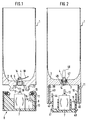
- FIG. 1 to 4 each show another embodiment of the drinking vessel according to the invention in longitudinal section.
- the drinking vessel 1 is designed as a drinking glass.
- an axial bore 3 is provided in the middle, in which the stirrer shaft 4 is rotatably mounted.
- the agitator shaft 4 is supported by a sleeve-shaped bearing ring 5, which preferably consists of a rubber-elastic material with a smooth inner surface, so that there is only a low sliding friction between the bearing ring 5 and the agitator shaft 4.
- the rubber-elastic material of the bearing ring 5 also seals the stirrer shaft 4.
- the sleeve 5 can for example consist of EPDM. So that the stirrer shaft 4 is secured in the bearing ring 5 in the axial direction, it has an annular projection 6 which engages in a corresponding annular groove in the inner surface of the bearing ring 5.
- the stirrer shaft 4 can be driven by an electric motor 7 which is arranged in a lower part 8.
- the electric motor 7 is supplied with power by a battery 9, which in the embodiment shown is designed as an accumulator battery that is charged by a solar cell 10.
- a switch 11 designed as a push button is provided, for example, for actuating the electric motor 7.
- the electrical connections between the electric motor 7, the battery 9, the solar cell 10 and the switch 11 are not shown in FIG. 1.
- the solar cell 10 which is designed as a film, is arranged on the outer circumference of the lower part 8, for example of cylindrical design, in a corresponding circumferential groove in the lower part 8 near the outside thereof.
- the material that covers the solar cell 10 to the outside must be translucent, that is, for example, made of a translucent plastic, such as acrylic glass.
- the solar cell 10 can extend practically around the entire outer circumference of the cylindrical lower part 8, with a recess in the area of the switch 11.
- a four-sided or other external polygonal pin 13 is fastened on the stirrer shaft 4 which can be inserted into a corresponding inner polygonal recess 14 in the stirrer shaft 4.
- the drinking vessel 1 can be placed on the lower part 8 and can be locked with it. This can be done on the lower part 8 z. B. with compression springs 15 loaded locking balls 16 or other spring-loaded locking body can be provided which engage in a groove 17 which is provided on the outside of a downwardly extending from the bottom 2 of the drinking vessel 1 annular projection 18.
- the electric motor 7 should have a speed of at least 1000 revolutions per minute, but the speed is preferably 8000 revolutions per minute and more.
- the drinking vessel 1 can be cleaned in a dishwasher with the built-in stirrer shaft 4 and the stirring tool 19.
- the beverage in the drinking vessel 1 can also be heated in a microwave oven before or after stirring.
- the sealing and bearing ring 5 with the stirrer shaft 4 and the stirring tool 19 can also be pressed out of the bore 3 in the base 2 of the vessel 1.
- the drinking vessel according to the invention can be used, for example, to mix coffee or tea with sugar, to prevent the formation of milk skin in milk, cocoa, coffee and tea, to produce types of fruit milk, to dissolve instant tea, instant coffee or cocoa powder, to stir freshly squeezed juices or to Preparation of egg liquid emulsions can be used.
- Protein granules or protein powder can also be mixed with it and instant drinks, isotonic drinks, milkshakes, vegetable juices and the like can be mixed.
- the stirrer can also be designed as a knife which simultaneously cuts the fruit, such as strawberries or pieces of banana.
- the drinking vessel according to the invention can in particular also be designed as a baby bottle.
- the lower part 8 can then be arranged in a baby bottle heating device. That is, the lower part 8 can be attached to the bottom of a vessel which is provided with an electric heating device and serves as a water bath for heating the contents of the baby bottle. So that the baby bottle is centered so that the pin 13 engages in the recess 14, a conical or the like tapering projection can be provided around the motor shaft, which engages in a correspondingly formed inner wall of the annular projection 18 on the bottom 2.
- a retractable spring drive can also be provided to drive the stirrer shaft 4.
- the lower part 8 can be provided with a musical work or the like acoustic display device.
- the motor or spring drive and the acoustic device can be actuated at the same time, for a predetermined period of time. In this way, it is acoustically indicated when the mixing of the contents of the drinking vessel 1 has ended.
- the embodiment according to FIG. 2 differs from that according to FIG. 1 essentially in that the drinking vessel 1 has a cylindrical foot 39 which has the same outer diameter as the drinking vessel 1 and receives the lower part 40. That is, the lower part 40 is, as shown in Fig. 2, inserted into the foot 39 and z. B. locked by means of a bayonet lock with the foot 39.
- lugs 41 are provided on the circumference of the lower part 40 in the lower region, which cooperate with the ring section 42 provided with recesses (not shown) on the inside of a sleeve 43 which is fastened to the inside of the foot 39.
- the lower part 40 can also be screwed into the foot 39.
- the lower part 40 according to FIG. 2 has a cylindrical peripheral wall 44, furthermore in the middle a recess for the motor 7.
- One or more batteries 9 are provided between the peripheral wall 44 and the motor 7.
- the solar cell 10 designed as a film is arranged between the sleeve 43 and the foot 39.
- the sleeve 43 can on the foot 39 z. B. be glued. So that a sufficiently large adhesive surface is obtained, the foot 39 and the sleeve 43 rest against one another at the lower edge via conical surfaces 45.
- the stirring thread 46 is designed as a closed loop according to FIG. 2.
- the bearing for the stirrer shaft 4 is formed in two parts according to FIG. 2, namely from a sealing ring 47 and a bearing ring 48 arranged underneath.
- a roller bearing can also be provided.
- the solar cell 10 can also be attached to the underside of the base 2 if the drinking vessel 1 is translucent in this area.
- the batteries 9 can also be charged with a charger instead of with the solar cell 10.
- a switch can be provided which is actuated when the top of the drinking vessel 1, which was previously suitably closed with a lid, is pressed.
- the motor 7 can also be firmly connected to the drinking vessel.
- the motor shaft is also the stirrer shaft.
- the drinking vessel 21 has a hollow cylindrical foot 22, in which a cylindrical part 23, which can be moved downwards out of the foot 22, is arranged, which is provided at the bottom with a base plate 24 which extends laterally beyond the hollow cylindrical foot 3 .
- the part 23 is arranged in the foot 22 by a not shown nose on the foot, which engages in a groove in the part 23, or another form-locking manner in the foot 22 so that it cannot rotate.
- the part 23 is provided with an internal thread 25, which extends in the direction of movement of the part 23 indicated by the arrow 26, namely in the longitudinal axis of the drinking vessel 21.
- a threaded spindle 27 engages, which passes through the bottom 28 downwardly projecting part of the stirrer shaft 29 is formed, on which a propeller 30 sits as a stirring tool.
- the weight of the part 23 is dimensioned such that it moves down from a standing surface when the drinking vessel 21 is lifted.
- a spring (not shown in the drawing) can also be provided, which presses the part 23 downwards. Characterized the spindle 27 and thus the propeller 30 is rotated, whereby the liquid present in the drinking vessel 1, not shown in the drawing, is mixed.
- the propeller 30 is rotated again until the part 23 reaches its upper end position shown in the drawing, in which the base plate 24 on the foot 22 is present.
- the part 23 can also have an external thread which engages in a corresponding internal thread in the hollow cylindrical foot 22.
- the stirrer shaft 29 can then be displaced in the axial direction in the part 23, but is arranged in a manner preventing rotation.
- a plate-shaped or disk-shaped foot 32 is provided, from which a threaded spindle 33 extends vertically upwards in the middle.
- the threaded spindle 33 engages in the stirrer shaft 36 which is provided with a nut 34 and is attached to the sleeve which extends upward from the bottom 35 of the drinking vessel 31.
- the weight of the foot 32 and the spindle 33 can be such that the foot 32 moves automatically into the screwed-out position shown in FIG. 4 when the drinking vessel 31 is raised.
- a freewheel can be provided, by means of which the foot 32 can be moved downwards when the drinking vessel 31 is raised without rotating.
- stirrer shaft protrudes through the bottom into the interior of the drinking vessel.
- stirrer shaft can also extend through a side wall into the stirring vessel.
Abstract
Description
Die vorliegende Erfindung bezieht sich auf ein Trinkgefäß mit einem an einer Rührerwelle befestigten Rührwerkzeug. Das Trinkgefäß kann z. B. eine Tasse, ein Trinkglas, ein Becher oder eine Babyflasche sein.The present invention relates to a drinking vessel with a stirring tool attached to a stirrer shaft. The drinking vessel can e.g. B. a cup, a drinking glass, a mug or a baby bottle.
Zum Verdünnen konzentrierter Säfte, Mixen von Cocktails, Auflösen von Zucker in Kaffee oder Tee oder zum Vermischen von Kaffee und Tee mit Milch, Zitronensaft oder anderen Flüssigkeiten, verwendet man heutzutage im allgemeinen einen Löffel. Das hat den Nachteil, daß dem Trinkgefäß immer ein Löffel beigelegt werden muß. Bei Getränken, die schwere Bestandteile enthalten, z. B. Fruchtfleisch, muß man nicht nur einmal, sondern wiederholt mit dem Löffel umrühren. Dies ist umständlich und vor allem dann lästig, wenn man z. B. bei einer Stehparty in einer Hand das Trinkgefäß und in der anderen z. B. einen Teller hält.A spoon is generally used these days to dilute concentrated juices, mix cocktails, dissolve sugar in coffee or tea, or mix coffee and tea with milk, lemon juice, or other liquids. This has the disadvantage that a spoon must always be added to the drinking vessel. For drinks that contain heavy ingredients, e.g. B. pulp, you have to stir not only once, but repeatedly with a spoon. This is cumbersome and especially annoying if you e.g. B. at a standing party in one hand the drinking vessel and in the other z. B. holds a plate.
Zum Mischen von Getränken ist aus US-A-1,174,828 ein Gefäß mit einem Deckel bekannt, durch den eine manuell betätigbare Rührerwelle mit einem Rührwerkzeug ragt. Um aus diesem Gefäß trinken zu können, müßte man also den Deckel mit dem Rührer abnehmen und irgendwo ablegen, wo er abtropfen kann, beispielsweise in einen Ausguß. Dieses Gefäß ist also nur sehr beschränkt als Trinkgefäß einsetzbar, nämlich nur dort, wo eine solche Abtropfmöglichkeit besteht. Auch ist die Reinigung relativ aufwendig, da sowohl das Gefäß wie der Deckel mit dem Rührwerkzeug gereinigt werden müssen.For mixing beverages, a vessel with a lid is known from US-A-1,174,828, through which a manually operable stirrer shaft with a stirring tool protrudes. In order to be able to drink from this vessel, one would have to remove the lid with the stirrer and place it somewhere where it can drip, for example into a sink. This vessel can therefore only be used to a very limited extent as a drinking vessel, namely only where there is such a possibility of dripping. Cleaning is also relatively complex since both the vessel and the lid have to be cleaned with the stirring tool.
Aus CH-A-142108 geht ein Trinkgefäß für moussierende Getränke, wie Bier, hervor, in dessen Boden eine mit Kohlendioxid füllbare Druckkammer mit einem Zufluß des Kohlendioxids in das Gefäßinnere vorgesehen ist. Das bekannte Gefäß ist also nur für kohlendioxidhaltige Getränke, nicht aber beispielsweise für Kaffee oder Milch geeignet. Nach DE-U-91 14 980 ist an einer Tasse ein Pfeifinstrument vorgesehen, dessen Luftröhre sich vom Henkel der Tasse nach unten zum Tassenboden erstreckt.CH-A-142108 discloses a drinking vessel for sparkling beverages, such as beer, in the bottom of which a pressure chamber which can be filled with carbon dioxide is provided with an inflow of the carbon dioxide into the interior of the vessel. The known vessel is therefore only suitable for carbon dioxide-containing beverages, but not, for example, for coffee or milk. According to DE-U-91 14 980, a whistling instrument is provided on a cup, the trachea of which extends from the handle of the cup down to the cup base.
Aufgabe der Erfindung ist es, ein leicht zu reinigendes Trinkgefäß mit einer wirksamen Rühreinrichtung bereitzustellen. Dies wird erfindungsgemäß mit dem im Anspruch 1 gekennzeichneten Trinkgefäß erreicht. In den Unteransprüchen sind vorteilhafte Ausgestaltungen der Erfindung wiedergegeben.The object of the invention is to provide an easy-to-clean drinking vessel with an effective stirring device. This is achieved according to the invention with the drinking vessel characterized in claim 1. Advantageous embodiments of the invention are given in the subclaims.
Nachstehend ist die Erfindung anhand der Zeichnung näher erläutert. Darin zeigen Fig. 1 bis 4 im Längsschnitt jeweils eine andere Ausführungsform des erfindungsgemäßen Trinkgefäßes.The invention is explained in more detail below with reference to the drawing. 1 to 4 each show another embodiment of the drinking vessel according to the invention in longitudinal section.
Gemäß Fig. 1 ist das Trinkgefäß 1 als Trinkglas ausgebildet. Im Boden 2 des Trinkgefäßes 1 ist in der Mitte eine Axialbohrung 3 vorgesehen, in der die Rührerwelle 4 drehbar gelagert ist.1, the drinking vessel 1 is designed as a drinking glass. In the bottom 2 of the drinking vessel 1, an axial bore 3 is provided in the middle, in which the
Die Lagerung der Rührerwelle 4 erfolgt durch einen hülsenförmigen Lagerring 5, welcher vorzugsweise aus einem gummielastischen Material mit glatter Innenfläche besteht, so daß zwischen dem Lagerring 5 und der Rührerwelle 4 nur eine geringe Gleitreibung besteht. Das gummielastische Material des Lagerrings 5 dichtet zugleich die Rührerwelle 4 ab. Die Hülse 5 kann beispielsweise aus EPDM bestehen. Damit die Rührerwelle 4 im Lagerring 5 in axialer Richtung gesichert ist, weist sie einen ringförmigen Vorsprung 6 auf, der in eine entsprechende Ringnut in der Innenfläche des Lagerrings 5 eingreift.The
Die Rührerwelle 4 ist durch einen Elektromotor 7 antreibbar, der in einem Unterteil 8 angeordnet ist. Der Elektromotor 7 wird von einer Batterie 9 mit Strom versorgt, die bei der dargestellten Ausführungsform als Akkumulatorbatterie ausgebildet ist, die durch eine Solarzelle 10 aufgeladen wird. Zur Betätigung des Elektromotors 7 ist beispielsweise ein als Druckknopf ausgebildeter Schalter 11 vorgesehen. Die elektrischen Verbindungen zwischen dem Elektromotor 7, der Batterie 9, der Solarzelle 10 und dem Schalter 11 sind in Fig. 1 nicht dargestellt.The
Die als Folie ausgebildete Solarzelle 10 ist am Außenumfang des beispielsweise zylindrisch ausgebildeten Unterteils 8 in einer entsprechenden Umfangsnut im Unterteil 8 nahe dessen Außenseite angeordnet. Das Material, das die Solarzelle 10 nach außen abdeckt, muß dazu lichtdurchlässig sein, also beispielsweise aus einem lichtdurchlässigen Kunststoff, wie Acrylglas, bestehen. Die Solarzelle 10 kann sich praktisch um den gesamten Außenumfang des zylindrischen Unterteils 8 erstrecken, mit einer Ausnehmung im Bereich des Schalters 11. Zur Kupplung der Antriebswelle 12 des Elektromotors 7 mit der Rührerwelle 4 ist auf der Rührerwelle 4 ein Vier- oder sonstiger Außenmehrkantzapfen 13 befestigt, der in eine entsprechende Innenmehrkantausnehmung 14 in der Rührerwelle 4 steckbar ist.The
Um die Motorantriebswelle 12 und die Rührerwelle 4 in der gekuppelten Stellung zu halten, ist das Trinkgefäß 1 auf das Unterteil 8 abstellbar und mit diesem verriegelbar ausgebildet. Dazu können an dem Unterteil 8 nach innen z. B. mit Druckfedern 15 belastete Rastkugeln 16 oder sonstige federbelastete Rastkörper vorgesehen sein, die in eine Nut 17 eingreifen, die an der Außenseite eines sich vom Boden 2 des Trinkgefäßes 1 nach unten erstreckenden ringförmigen Vorsprungs 18 vorgesehen ist.In order to keep the
Als Rührwerkzeug ist ein Draht oder Faden 19, beispielsweise aus Nylon oder dergleichen Kunststoff, vorgesehen, der mit einem Ende an der Rührerwelle 4 befestigt ist. Es hat sich gezeigt, daß ein solcher relativ kurzer Faden 19 von 5 cm oder weniger sich besonders gut zum Verrühren von pulverförmigen Stoffen eignet, die zum Verklumpen neigen, wie Kakaopulver, Proteingranulat usw., und zwar bildet sich beim Rühren mit dem Faden 19 ein Strudel aus, der das Pulver nach unten saugt und etwaige Klumpen zertrümmert. Zugleich lassen sich mit einem Faden 18 als Rührwerkzeug sehr hohe Tourenzahlen mit relativ geringem Energieaufwand erzielen. Der Elektromotor 7 sollte eine Drehzahl von mindestens 1000 Umdrehungen pro Minute aufweisen, vorzugsweise liegt die Drehzahl jedoch bei 8000 Umdrehungen pro Minute und mehr.A wire or
Das Trinkgefäß 1 kann mit eingebauter Rührerwelle 4 und dem Rührwerkzeug 19 in einer Geschirrspülmaschine gereinigt werden. Auch kann das Getränk in dem Trinkgefäß 1 vor oder nach dem Rühren in einem Mikrowellenofen erwärmt werden.The drinking vessel 1 can be cleaned in a dishwasher with the built-
Wenn beispielsweise eine Intensivreinigung vorgenommen werden soll, kann der Dicht- und Lagerring 5 mit der Rührerwelle 4 und dem Rührwerkzeug 19 auch aus der Bohrung 3 im Boden 2 des Gefäßes 1 herausgedrückt werden.If, for example, intensive cleaning is to be carried out, the sealing and bearing ring 5 with the
Das erfindungsgemäße Trinkgefäß kann beispielsweise zum Vermengen von Kaffee oder Tee mit Zucker, zum Verhindern der Bildung einer Milchhaut bei Milch, Kakao, Kaffee und Tee, zum Herstellen von Fruchtmilchsorten, zum Auflösen von Instanttee, Löskaffee oder Kakaopulver, zum Rühren frisch gepreßter Säfte oder zur Herstellung von Eiflüssigkeiten-Emulsionen verwendet werden. Auch können mit ihm Proteingranulate oder Eiweißpulver vermischt und Instantdrinks, isotonische Getränke, Milchshakes, Gemüsesäfte und dergleichen verrührt werden. Insbesondere wenn Frucht-Milchgetränke hergestellt werden, kann das Rührwerk auch als Messer ausgebildet sein, das die Früchte, wie Erdbeeren oder Bananenstücke, zugleich zerteilt.The drinking vessel according to the invention can be used, for example, to mix coffee or tea with sugar, to prevent the formation of milk skin in milk, cocoa, coffee and tea, to produce types of fruit milk, to dissolve instant tea, instant coffee or cocoa powder, to stir freshly squeezed juices or to Preparation of egg liquid emulsions can be used. Protein granules or protein powder can also be mixed with it and instant drinks, isotonic drinks, milkshakes, vegetable juices and the like can be mixed. In particular if fruit milk beverages are produced, the stirrer can also be designed as a knife which simultaneously cuts the fruit, such as strawberries or pieces of banana.
Das erfindungsgemäße Trinkgefäß kann insbesondere auch als Babyflasche ausgebildet sein. Das Unterteil 8 kann dann in einer Babyflaschenerwärmeinrichtung angeordnet sein. D. h., das Unterteil 8 kann am Boden eines Gefäßes angebracht werden, das mit einer elektrischen Heizeinrichtung versehen ist und als Wasserbad zum Erwärmen des Babyflascheninhalts dient. Damit die Babyflasche so zentriert wird, daß der Zapfen 13 in die Ausnehmung 14 eingreift, kann um die Motorwelle ein kegelförmiger oder dergleichen sich nach oben verjüngender Vorsprung vorgesehen sein, der in eine entsprechend ausgebildete Innenwand des ringförmigen Vorsprungs 18 am Boden 2 eingreift.The drinking vessel according to the invention can in particular also be designed as a baby bottle. The lower part 8 can then be arranged in a baby bottle heating device. That is, the lower part 8 can be attached to the bottom of a vessel which is provided with an electric heating device and serves as a water bath for heating the contents of the baby bottle. So that the baby bottle is centered so that the
Statt eines Motors kann zum Antrieb der Rührerwelle 4 auch ein aufziehbarer Federantrieb vorgesehen sein. Ferner kann das Unterteil 8 mit einem Musikwerk oder dergleichen akustischen Anzeigevorrichtung versehen sein. Mit einer Zeitschalteinrichtung kann der Motor bzw. Federantrieb und die akustische Vorrichtung zugleich betätigt werden, und zwar einen vorgegebenen Zeitraum lang. Auf diese Weise wird akustisch angezeigt, wann das Mischen des Inhalts des Trinkgefäßes 1 beendet ist.Instead of a motor, a retractable spring drive can also be provided to drive the
Die Ausführungsform nach Fig. 2 unterscheidet sich von derjenigen nach Fig. 1 im wesentlichen dadurch, daß das Trinkgefäß 1 einen zylinderförmigen Fuß 39 aufweist, der den gleichen Außendurchmesser wie das Trinkgefäß 1 aufweist und das Unterteil 40 aufnimmt. D. h., das Unterteil 40 wird, wie in Fig. 2 dargestellt, in den Fuß 39 gesteckt und im eingeschobenen Zustand z. B. mittels eines Bajonett-Verschlusses mit dem Fuß 39 verriegelt. Dazu sind am Umfang des Unterteils 40 im unteren Bereich Nasen 41 vorgesehen, die mit dem mit nicht dargestellten Ausnehmungen versehenen Ringabschnitt 42 an der Innenseite einer Hülse 43 zusammenwirken, die an der Innenseite des Fußes 39 befestigt ist.The embodiment according to FIG. 2 differs from that according to FIG. 1 essentially in that the drinking vessel 1 has a
Statt des Bajonett-Verschlusses kann das Unterteil 40 auch in den Fuß 39 einschraubbar sein.Instead of the bayonet catch, the
Das Unterteil 40 nach Fig. 2 weist eine zylindrische Umfangswand 44 auf, ferner in der Mitte eine Ausnehmung für den Motor 7. Zwischen der Umfangswand 44 und dem Motor 7 sind eine oder mehrere Batterien 9 vorgesehen.The
Zwischen der Hülse 43 und dem Fuß 39 ist die als Folie ausgebildete Solarzelle 10 angeordnet.The
Die Hülse 43 kann an den Fuß 39 z. B. angeklebt sein. Damit eine hinreichend große Klebefläche erhalten wird, liegen der Fuß 39 und die Hülse 43 an der unteren Kante über Konusflächen 45 aneinander an.The
Nicht dargestellte Kontakte verbinden den Schalter 11 und die die Solarzelle 10 mit dem Motor 7 und der Batterie 9. Der Rührfaden 46 ist nach Fig. 2 als geschlossene Schleife ausgebildet.Contacts, not shown, connect the
Das Lager für die Rührerwelle 4 ist nach Fig. 2 zweiteilig ausgebildet, und zwar aus einem Dichtungsring 47 und einem darunter angeordneten Lagerring 48. Anstelle des Gleitlagers mit dem Lagerring 48 kann auch ein Wälzlager vorgesehen sein.The bearing for the
Statt am Umfang des Fußes 39 kann die Solarzelle 10 auch an der Unterseite des Bodens 2 angebracht sein, wenn das Trinkgefäß 1 in diesem Bereich lichtdurchlässig ist. Die Batterien 9 können statt mit der Solarzelle 10 auch mit einem Ladegerät aufgeladen werden.Instead of on the circumference of the
Statt des Schalters 11 kann ein Schalter vorgesehen sein, der betätigt wird, wenn man auf das vorher zweckmäßigerweise mit einem Deckel verschlossene Trinkgefäß 1 von oben drückt.Instead of the
Statt des Motors 7 in einem separaten Unterteil 40 kann der Motor 7 auch fest mit dem Trinkgefäß verbunden sein. In diesem Fall ist die Motorwelle zugleich die Rührerwelle.Instead of the motor 7 in a separate
Gemäß Fig. 3 weist das Trinkgefäß 21 einen hohlzylindrischen Fuß 22 auf, in dem ein sich nach unten aus dem Fuß 22 herausbewegbares zylindrisches Teil 23 angeordnet ist, das unten mit einer Standplatte 24 versehen ist, die sich seitlich über den hohlzylindrischen Fuß 3 hinaus erstreckt.According to FIG. 3, the
Das Teil 23 ist in dem Fuß 22 durch eine nicht dargestellte Nase am Fuß, die in eine Nut im Teil 23 eingreift, oder einen anderen Formschluß verdrehungssicher im Fuß 22 verschiebbar angeordnet.The part 23 is arranged in the foot 22 by a not shown nose on the foot, which engages in a groove in the part 23, or another form-locking manner in the foot 22 so that it cannot rotate.
Das Teil 23 ist mit einem Innengewinde 25 versehen, das sich in der durch den Pfeil 26 wiedergegebenen Bewegungsrichtung des Teiles 23 erstreckt, und zwar in der Längsachse des Trinkgefäßes 21. In das Innengewinde 25 greift eine Gewindespindel 27 ein, die durch den aus dem Boden 28 nach unten ragenden Teil der Rührerwelle 29 gebildet wird, auf der ein Propeller 30 als Rührwerkzeug sitzt.The part 23 is provided with an
Das Gewicht des Teiles 23 ist so bemessen, daß es sich beim Anheben des Trinkgefäßes 21 von einer Standfläche nach unten bewegt. Auch kann eine in der Zeichnung nicht dargestellte Feder vorgesehen sein, die das Teil 23 nach unten drückt. Dadurch wird die Spindel 27 und damit der Propeller 30 in Drehung versetzt, wodurch die in dem Trinkgefäß 1 vorhandene, in der Zeichnung nicht dargestellte Flüssigkeit durchmischt wird. Wenn das Teil 23 nach dem Anheben seine untere Endstellung erreicht hat und das Trinkgefäß 21 erneut abgestellt wird, wird der Propeller 30 nochmals in Umdrehung versetzt, bis das Teil 23 seine in der Zeichnung dargestellte obere Endstellung erreicht, in der die Standplatte 24 an dem Fuß 22 anliegt.The weight of the part 23 is dimensioned such that it moves down from a standing surface when the
Statt der Gewindespindel 27 an der Rührerwelle 29 kann das Teil 23 auch ein Außengewinde aufweisen, das in ein entsprechendes Innengewinde im hohlzylindrischen Fuß 22 eingreift. Bei dieser in der Zeichnung nicht dargestellten Ausführungsform ist dann die Rührerwelle 29 im Teil 23 in Axialrichtung verschiebbar, jedoch verdrehungssicher angeordnet.Instead of the threaded
Bei der Ausführungsform nach Fig. 4 ist ein platten- oder scheibenförmiger Fuß 32 vorgesehen, von dem sich in der Mitte eine Gewindespindel 33 senkrecht nach oben erstreckt. Die Gewindespindel 33 greift in die mit einer Mutter 34 versehene als Hohlwelle ausgebildete Rührerwelle 36 ein, die an der sich vom Boden 35 des Trinkgefäßes 31 nach oben erstreckenden Hülse befestigt ist. Wenn die Spindel 33 aus der Mutter 34 herausgeschraubt ist, wie in Fig. 3 dargestellt, und der Fuß 32 auf eine Unterlage gestellt wird, führt das Gewicht des Trinkgefäßes 31 mit der darin enthaltenen, nicht dargestellten Flüssigkeit dazu, daß sich das Trinkgefäß 31 unter Rotation nach unten bewegt, wodurch in dem Trinkgefäß 31 Zentrifugalkräfte auftreten, die zu einer Vermischung des Inhalts des Trinkgefäßes 31 führen. Als Rührwerkzeug können z. B. Rippen 37 an der Innenseite des Trinkgefäßes 31 vorgesehen sein.In the embodiment according to FIG. 4, a plate-shaped or disk-shaped
Das Gewicht des Fußes 32 und der Spindel 33 können so bemessen sein, daß sich der Fuß 32 von selbst in die in Fig. 4 dargestellte herausgeschraubte Position bewegt, wenn das Trinkgefäß 31 angehoben wird.The weight of the
In Weiterbildung der Ausführungsform nach Fig. 4 kann ein Freilauf vorgesehen sein, durch den der Fuß 32 beim Hochheben des Trinkgefäßes 31 nach unten bewegbar ist, ohne sich zu drehen.In a further development of the embodiment according to FIG. 4, a freewheel can be provided, by means of which the
Bei den vorstehend geschilderten Ausführungsformen ragt die Rührerwelle durch den Boden in das Innere des Trinkgefäßes.In the embodiments described above, the stirrer shaft protrudes through the bottom into the interior of the drinking vessel.
Stattdessen kann sich die Rührerwelle auch durch eine Seitenwand in das Rührgefäß erstrecken.Instead, the stirrer shaft can also extend through a side wall into the stirring vessel.
Claims (11)
Applications Claiming Priority (3)
| Application Number | Priority Date | Filing Date | Title |
|---|---|---|---|
| DE4209899 | 1992-03-26 | ||
| DE4209899 | 1992-03-26 | ||
| CA002096190A CA2096190A1 (en) | 1992-03-26 | 1993-05-13 | Drinking vessel |
Publications (1)
| Publication Number | Publication Date |
|---|---|
| EP0562310A1 true EP0562310A1 (en) | 1993-09-29 |
Family
ID=25676186
Family Applications (1)
| Application Number | Title | Priority Date | Filing Date |
|---|---|---|---|
| EP93103319A Withdrawn EP0562310A1 (en) | 1992-03-26 | 1993-03-02 | Drinking glass |
Country Status (3)
| Country | Link |
|---|---|
| EP (1) | EP0562310A1 (en) |
| CN (1) | CN1078372A (en) |
| CA (1) | CA2096190A1 (en) |
Cited By (21)
| Publication number | Priority date | Publication date | Assignee | Title |
|---|---|---|---|---|
| WO1997007724A1 (en) * | 1994-03-21 | 1997-03-06 | Oesterlund Bo | Shaker for preparation of gruel directly in a gruel bottle |
| US5692830A (en) * | 1996-08-09 | 1997-12-02 | Coastal Sales Associates, Inc. | Rotating mixer and tray |
| WO1997047269A1 (en) * | 1996-06-11 | 1997-12-18 | Teglbjaerg Caspar | Feeding bottle |
| US5720552A (en) * | 1993-12-17 | 1998-02-24 | Schindlegger; Walter | Drinking glass with integrated stirring assembly |
| US5855431A (en) * | 1996-08-09 | 1999-01-05 | Coastal Sales Associates, Inc. | Rotating mixer and tray |
| WO1999021466A1 (en) * | 1997-10-29 | 1999-05-06 | Shane Robert Mcgill | Food blending apparatus |
| US5911504A (en) * | 1996-01-18 | 1999-06-15 | Schindlegger, Jr.; Walter | Stirring device for a personal beverage container |
| US6193407B1 (en) | 1998-09-30 | 2001-02-27 | Hp Intellectual Corp. | Battery-operated liquifier |
| US6338569B1 (en) | 1998-10-27 | 2002-01-15 | Mcgill Shane R. | Food blending apparatus |
| US6796705B1 (en) | 2003-05-06 | 2004-09-28 | OnTel Products Corp. | Motorized frothing mug and method of using same |
| US6817750B1 (en) * | 2003-08-26 | 2004-11-16 | Homeland Housewares, Llc | Individualized blender |
| US6854875B2 (en) | 1997-10-29 | 2005-02-15 | Mcgill Technology Limited | Food blending apparatus |
| US7422362B2 (en) | 2003-08-26 | 2008-09-09 | Homeland Housewares, Llc | Portable blender |
| US7441944B2 (en) | 2003-08-26 | 2008-10-28 | Homeland Housewares, Llc | Drinking extension for blender container |
| USD649400S1 (en) | 2010-12-20 | 2011-11-29 | Baby Bullet, LLC | Kitchen food processor container |
| USD649834S1 (en) | 2010-12-20 | 2011-12-06 | Baby Bullet, LLC | Food storage cup |
| DE102014204262A1 (en) * | 2014-03-07 | 2015-09-10 | Genius Gmbh | Food comminution device |
| CN105411319A (en) * | 2015-12-08 | 2016-03-23 | 杨春茵 | Automatic stirring cup |
| EP3289929A1 (en) | 2016-08-30 | 2018-03-07 | Vetrerie Di Empoli S.p.A. | Improved glass |
| WO2018202577A1 (en) * | 2017-05-04 | 2018-11-08 | Nestec S.A. | Process of preparation of a coffee-based beverage |
| US11918926B2 (en) | 2019-02-15 | 2024-03-05 | Spin Master Ltd. | Toy assembly and extensible object therefor |
Families Citing this family (7)
| Publication number | Priority date | Publication date | Assignee | Title |
|---|---|---|---|---|
| US6962432B2 (en) * | 2003-02-10 | 2005-11-08 | Hp Intellectual Corp. | Machine for mixing and dispensing salad dressings |
| CN105581651B (en) * | 2014-10-24 | 2018-05-08 | 北京数码视讯科技股份有限公司 | A kind of smart seat of water dispenser and water dispenser |
| CN105125023A (en) * | 2015-10-20 | 2015-12-09 | 泉州市尊生酒业有限公司 | Two-purpose medicinal liquor cup |
| DE102016216101A1 (en) | 2016-08-26 | 2018-03-01 | BSH Hausgeräte GmbH | Connecting device for coupling an attachment to a food processor |
| CN107212767A (en) * | 2017-07-03 | 2017-09-29 | 叶吉利 | A kind of drinking cup device |
| CN107115035B (en) * | 2017-07-07 | 2019-01-18 | 平湖市浩鑫塑胶有限公司 | A kind of cup device |
| CN107260020B (en) * | 2017-07-07 | 2019-07-02 | 永康市光芒工贸有限公司 | A kind of convenient cup device |
Citations (2)
| Publication number | Priority date | Publication date | Assignee | Title |
|---|---|---|---|---|
| US1174828A (en) * | 1915-06-10 | 1916-03-07 | Alonzo Copeland | Drink-mixer. |
| EP0250245A2 (en) * | 1986-06-18 | 1987-12-23 | Chubu Industries, Inc. | Apparatus for making soft ice-drink |
-
1993
- 1993-03-02 EP EP93103319A patent/EP0562310A1/en not_active Withdrawn
- 1993-03-25 CN CN 93103595 patent/CN1078372A/en active Pending
- 1993-05-13 CA CA002096190A patent/CA2096190A1/en not_active Abandoned
Patent Citations (2)
| Publication number | Priority date | Publication date | Assignee | Title |
|---|---|---|---|---|
| US1174828A (en) * | 1915-06-10 | 1916-03-07 | Alonzo Copeland | Drink-mixer. |
| EP0250245A2 (en) * | 1986-06-18 | 1987-12-23 | Chubu Industries, Inc. | Apparatus for making soft ice-drink |
Cited By (38)
| Publication number | Priority date | Publication date | Assignee | Title |
|---|---|---|---|---|
| US5720552A (en) * | 1993-12-17 | 1998-02-24 | Schindlegger; Walter | Drinking glass with integrated stirring assembly |
| WO1997007724A1 (en) * | 1994-03-21 | 1997-03-06 | Oesterlund Bo | Shaker for preparation of gruel directly in a gruel bottle |
| US5911504A (en) * | 1996-01-18 | 1999-06-15 | Schindlegger, Jr.; Walter | Stirring device for a personal beverage container |
| AU726209B2 (en) * | 1996-06-11 | 2000-11-02 | Caspar Teglbjarg | Feeding container |
| WO1997047269A1 (en) * | 1996-06-11 | 1997-12-18 | Teglbjaerg Caspar | Feeding bottle |
| US6123065A (en) * | 1996-06-11 | 2000-09-26 | Teglbjarg; Caspar | Feeding bottle |
| US5692830A (en) * | 1996-08-09 | 1997-12-02 | Coastal Sales Associates, Inc. | Rotating mixer and tray |
| US5855431A (en) * | 1996-08-09 | 1999-01-05 | Coastal Sales Associates, Inc. | Rotating mixer and tray |
| AU736689B2 (en) * | 1997-10-29 | 2001-08-02 | Shane Robert Mcgill | Food blending apparatus |
| WO1999021466A1 (en) * | 1997-10-29 | 1999-05-06 | Shane Robert Mcgill | Food blending apparatus |
| US7168845B2 (en) | 1997-10-29 | 2007-01-30 | Mcgill Technology Limited | Food blending apparatus |
| US7993053B2 (en) | 1997-10-29 | 2011-08-09 | Mcgill Technology Limited | Food blending apparatus |
| EP1279359A3 (en) * | 1997-10-29 | 2003-12-10 | McGILL TECHNOLOGY LIMITED | Food blending apparatus |
| US7758236B2 (en) | 1997-10-29 | 2010-07-20 | Mcgill Technology Limited | Food blending apparatus |
| US7309156B2 (en) | 1997-10-29 | 2007-12-18 | Mcgill Technology Limited | Food blending apparatus and method of use |
| US6854875B2 (en) | 1997-10-29 | 2005-02-15 | Mcgill Technology Limited | Food blending apparatus |
| EP1563779A2 (en) * | 1997-10-29 | 2005-08-17 | McGILL TECHNOLOGY LIMITED | Food blending apparatus |
| EP1563779A3 (en) * | 1997-10-29 | 2005-08-24 | McGILL TECHNOLOGY LIMITED | Food blending apparatus |
| EP1637056A2 (en) * | 1997-10-29 | 2006-03-22 | McGILL TECHNOLOGY LIMITED | Food blending apparatus |
| EP1637056A3 (en) * | 1997-10-29 | 2006-04-19 | McGILL TECHNOLOGY LIMITED | Food blending apparatus |
| US7147365B2 (en) | 1997-10-29 | 2006-12-12 | Mcgill Technology Limited | Method of dispensing blended food products |
| US6193407B1 (en) | 1998-09-30 | 2001-02-27 | Hp Intellectual Corp. | Battery-operated liquifier |
| US6338569B1 (en) | 1998-10-27 | 2002-01-15 | Mcgill Shane R. | Food blending apparatus |
| US6796705B1 (en) | 2003-05-06 | 2004-09-28 | OnTel Products Corp. | Motorized frothing mug and method of using same |
| US6817750B1 (en) * | 2003-08-26 | 2004-11-16 | Homeland Housewares, Llc | Individualized blender |
| US7422362B2 (en) | 2003-08-26 | 2008-09-09 | Homeland Housewares, Llc | Portable blender |
| US7430957B2 (en) | 2003-08-26 | 2008-10-07 | Homeland Housewares, Llc | Blender and juicer system |
| US7441944B2 (en) | 2003-08-26 | 2008-10-28 | Homeland Housewares, Llc | Drinking extension for blender container |
| US7958819B2 (en) | 2003-08-26 | 2011-06-14 | Homeland Housewares, Llc | Blender and juicer system |
| US8122821B2 (en) | 2003-08-26 | 2012-02-28 | Homeland Housewares, Llc | Food-processing device |
| USD649834S1 (en) | 2010-12-20 | 2011-12-06 | Baby Bullet, LLC | Food storage cup |
| USD649400S1 (en) | 2010-12-20 | 2011-11-29 | Baby Bullet, LLC | Kitchen food processor container |
| DE102014204262A1 (en) * | 2014-03-07 | 2015-09-10 | Genius Gmbh | Food comminution device |
| DE102014204262B4 (en) * | 2014-03-07 | 2016-06-30 | Genius Gmbh | Food comminution device |
| CN105411319A (en) * | 2015-12-08 | 2016-03-23 | 杨春茵 | Automatic stirring cup |
| EP3289929A1 (en) | 2016-08-30 | 2018-03-07 | Vetrerie Di Empoli S.p.A. | Improved glass |
| WO2018202577A1 (en) * | 2017-05-04 | 2018-11-08 | Nestec S.A. | Process of preparation of a coffee-based beverage |
| US11918926B2 (en) | 2019-02-15 | 2024-03-05 | Spin Master Ltd. | Toy assembly and extensible object therefor |
Also Published As
| Publication number | Publication date |
|---|---|
| CA2096190A1 (en) | 1994-11-14 |
| CN1078372A (en) | 1993-11-17 |
Similar Documents
| Publication | Publication Date | Title |
|---|---|---|
| EP0562310A1 (en) | Drinking glass | |
| EP0814694A1 (en) | Stirring device | |
| DE60112819T2 (en) | Drink mixer | |
| US4561782A (en) | Tamping and stirring rod for use with a food and beverage blender | |
| EP1449472B2 (en) | Hand driven food cutter | |
| DE69836107T2 (en) | Mixer for food | |
| EP2555658B1 (en) | Beverage maker having a lockable actuation rod | |
| WO2007128155A1 (en) | Device for processing foodstuffs | |
| EP1361917B1 (en) | Device for mixing and homogenizing materials in laboratory test container with a stirring element | |
| DE212018000003U1 (en) | Cup with compression-driven agitators | |
| EP2470054B1 (en) | Device and method for mixing material to be mixed | |
| DE102006014471A1 (en) | Stirring device for stirring drinks comprises a stirring tool placed on a screw shaft fixed in a container and having permanent magnets influenced by magnets arranged outside of the container to move the stirring tool along the screw shaft | |
| DE2845956A1 (en) | LID WITH A WIDTH, WHICH IS EQUALLY HORIZONTAL, WITH A CENTRAL OPENING, AND VESSEL SET WITH SUCH A LID | |
| DE1052079B (en) | Mixer or shredder for the household | |
| DE2653679A1 (en) | HANDHELD HOUSEHOLD APPLIANCE FOR MIXING FOOD | |
| CH284332A (en) | Household machine. | |
| EP0151310B1 (en) | Food processor with mixing bowl | |
| WO2015139863A1 (en) | Device and method for mixing material to be mixed | |
| WO2002000078A1 (en) | Working container for receiving and processing foodstuffs | |
| DE4033020A1 (en) | Multipurpose kitchen food processor - has motor powered hand operated unit provided with working tools such as kneading claws and egg beaters | |
| DE3439654A1 (en) | Process and apparatus for uniform distribution of yeast particles in yeast-containing beer | |
| DE102014002316B4 (en) | Mobile blender for drinks | |
| DE20122168U1 (en) | Beverage blender | |
| EP0761146B1 (en) | Drinking container | |
| DE977303C (en) | Working container that can be placed on an electromotive drive base for high-speed kitchen appliances |
Legal Events
| Date | Code | Title | Description |
|---|---|---|---|
| PUAI | Public reference made under article 153(3) epc to a published international application that has entered the european phase |
Free format text: ORIGINAL CODE: 0009012 |
|
| AK | Designated contracting states |
Kind code of ref document: A1 Designated state(s): AT BE CH DE DK ES FR GB GR IE IT LI LU NL PT SE |
|
| 17P | Request for examination filed |
Effective date: 19940324 |
|
| 17Q | First examination report despatched |
Effective date: 19950929 |
|
| STAA | Information on the status of an ep patent application or granted ep patent |
Free format text: STATUS: THE APPLICATION HAS BEEN WITHDRAWN |
|
| 18W | Application withdrawn |
Withdrawal date: 19960418 |