EP0562089B1 - Pet access door frame modular unit - Google Patents
Pet access door frame modular unit Download PDFInfo
- Publication number
- EP0562089B1 EP0562089B1 EP92921772A EP92921772A EP0562089B1 EP 0562089 B1 EP0562089 B1 EP 0562089B1 EP 92921772 A EP92921772 A EP 92921772A EP 92921772 A EP92921772 A EP 92921772A EP 0562089 B1 EP0562089 B1 EP 0562089B1
- Authority
- EP
- European Patent Office
- Prior art keywords
- frame
- frames
- unit
- exterior
- access door
- Prior art date
- Legal status (The legal status is an assumption and is not a legal conclusion. Google has not performed a legal analysis and makes no representation as to the accuracy of the status listed.)
- Expired - Lifetime
Links
Images


Classifications
-
- E—FIXED CONSTRUCTIONS
- E06—DOORS, WINDOWS, SHUTTERS, OR ROLLER BLINDS IN GENERAL; LADDERS
- E06B—FIXED OR MOVABLE CLOSURES FOR OPENINGS IN BUILDINGS, VEHICLES, FENCES OR LIKE ENCLOSURES IN GENERAL, e.g. DOORS, WINDOWS, BLINDS, GATES
- E06B7/00—Special arrangements or measures in connection with doors or windows
- E06B7/28—Other arrangements on doors or windows, e.g. door-plates, windows adapted to carry plants, hooks for window cleaners
- E06B7/32—Serving doors; Passing-through doors ; Pet-doors
-
- A—HUMAN NECESSITIES
- A01—AGRICULTURE; FORESTRY; ANIMAL HUSBANDRY; HUNTING; TRAPPING; FISHING
- A01K—ANIMAL HUSBANDRY; AVICULTURE; APICULTURE; PISCICULTURE; FISHING; REARING OR BREEDING ANIMALS, NOT OTHERWISE PROVIDED FOR; NEW BREEDS OF ANIMALS
- A01K1/00—Housing animals; Equipment therefor
- A01K1/02—Pigsties; Dog-kennels; Rabbit-hutches or the like
- A01K1/035—Devices for use in keeping domestic animals, e.g. fittings in housings or dog beds
-
- E—FIXED CONSTRUCTIONS
- E05—LOCKS; KEYS; WINDOW OR DOOR FITTINGS; SAFES
- E05C—BOLTS OR FASTENING DEVICES FOR WINGS, SPECIALLY FOR DOORS OR WINDOWS
- E05C9/00—Arrangements of simultaneously actuated bolts or other securing devices at well-separated positions on the same wing
-
- E—FIXED CONSTRUCTIONS
- E05—LOCKS; KEYS; WINDOW OR DOOR FITTINGS; SAFES
- E05C—BOLTS OR FASTENING DEVICES FOR WINGS, SPECIALLY FOR DOORS OR WINDOWS
- E05C9/00—Arrangements of simultaneously actuated bolts or other securing devices at well-separated positions on the same wing
- E05C9/18—Details of fastening means or of fixed retaining means for the ends of bars
- E05C9/1825—Fastening means
- E05C9/1833—Fastening means performing sliding movements
- E05C9/185—Fastening means performing sliding movements parallel with actuating bar
- E05C2009/1866—Fastening means performing sliding movements parallel with actuating bar of the keyhole slot type
Definitions
- This invention relates to pet access doors and more particularly to a modular version of pet access doors and frames.
- a pet access door with the features of the first part of claim 1 is, for instance, known from US-A-2,758,646.
- Pet access doors allow the passage of small pets through holes in doors or walls. Originally they consisted principally of a frame mounted on the surface of the door or wall at the edges of a hole that had been cut, and a door hinged on the frame to keep the elements out but to allow passage of a small animal through the hole by its pushing against the hinged door. For security purposes a frame was often mounted on the inside surface of the door or wall, with some arrangement for a sturdy security panel to be affixed to this inside frame so that it was not removable from the outside. Examples of such frames can be found in the present inventor's earlier U.S. patents nos. 4,408,416 and 4,651,793.
- any good pet access door unit is security of the building in which the door is used, functionality (that is, that it be convenient to use and provide protection from the elements for the building in which it is used), appearance, and strength. It is an object of this invention to provide a modular construction of a pet access door unit that meets these goals. Other objects are to allow use of two flaps in a constructed unit, to provide a security cover that may be applied in a horizontal motion, to allow attachment or removal of a flap to or from the frame while the frame is in place, and to provide for an automatically adjustable magnetic sill.
- the invention provides a pet access door unit for insertion into a hole cut in a door or wall having two exterior frames defining an opening, for mounting at an edge of the hole on opposite sides of the hole. At least one of the exterior frames includes attachment means for attaching a pet access door.
- the unit includes one or more spacer frames defining an opening, for insertion into the hole between the exterior frames, the spacer frames being in telescoping arrangement with the exterior frame, and also includes means for fastening the exterior frames to the spacer frames.
- the spacer frames have fastener brackets for fasteners extending horizontally to adjustably fasten the exterior frames and the spacer frames into a unit, and the spacer frames have nestable tongue and groove surfaces for abutting relationship to each other.
- both exterior frames have attachment means for attaching pet access doors.
- Another aspect of the invention further includes a plurality of posts extending horizontally from the exterior frame, a security panel sized to close the opening, and at least one slider, slidably mounted in the security panel with means to engage the posts.
- the posts bear annular grooves and the slider defines keyhole-shaped holes with lower wider and upper narrower portions, the portion of the slider with the narrower portion of the hole being engagable with the post grooves, whereby the security panel may be moved to the frame in a horizontal motion for securing to the frame.
- the portion of the slider adjacent the lower edge of the wider portion of the keyhole-shaped hole has an edge portion displaced to not engage the post groove.
- Another aspect of the invention further includes a pet access door securing bar for capturing an upper portion of the pet access door between the bar and the frame, and at least one fastener for fastening the bar to the frame.
- the exterior frame defines a first lip portion
- the bar defines a second lip portion
- the pet access door has an upper portion including projecting portions captured by the lip portions when the bar is fastened to the frame.
- the pet access door is hingedly mounted on the frame in the pet passage opening and has a magnet-attracting bottom portion, a sill vertically movably mounted bottom portion, a sill vertically movably mounted beneath the pet access door on the exterior frame, magnets being mounted in the sill so that the sill may be attracted toward the pet access door, and releasable fasteners for fastening the sill to the frame when the sill is closely adjacent the pet access door.
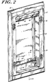
- a frame unit 10 consists of inside and outside surface mounted exterior frames 12, 14, respectively, and a number of spacer frames 16 in between.
- the inside exterior surface mounted frame 12 has a flap 18.
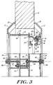
- Fig. 3 is a cross-sectional view of the unit 10 assembled through a hole cut in a door or wall 15.
- the number of spacer frames 16 is determined by the depth of the door or wall 15 through which a hole has been cut.
- the horizontally extending wall 20 of the inside exterior flap-bearing frame 12 has dimensions selected so that it may telescope through the inside of the spacer frame 16, making some adjustment of the width of the unit 10 possible (see Fig. 3).
- the amount of adjustment possible is equal to the width of one of the spacer frames 16. In short, an adjustment can be made in the width of the entire unit 10 up to the point that another spacer frame 16 is necessary.
- Each exterior frame 12, 14 has a beveled exterior surface wall 22 to cover the perimeter of the hole cut through the door or wall.
- the exterior surface wall 22 includes a flat perimeter surface 24 with holes 26 for fasteners 28a, 28b for attachment of the exterior frame 12, 14 to the rest of the unit 10.
- the flap-bearing exterior frame 12 has, in addition, a top portion 30 (see Figs. 1 and 3) that includes a short wall 32 onto which a flap holder 34 can be secured.
- the short wall 32 includes a bottom lip 36 above which protruding elements 38 of the flap 18 are located.
- the flap holder, or bar, 34 includes another lower lip 40 for capturing the projections 38 at the top of the flap 18.
- the holder 34 also includes two diagonal struts 42 with holes 44 through them aligned with threaded holes 46 in the top 30 of the frame 12.
- the holes 44 drilled through the struts 42 are oriented so that screws 48 enter them at a 45° angle (see Fig. 1).
- the screws 48 through the holder 34 are captured in the threaded holes 46 at the top 30 of the frame 12 to hold the flap 18 in place.
- the flap 18 is made of pliable plastic so that it can bend and be pushed easily by a pet moving through the unit 10.
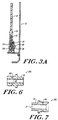
- the bottom 50 of the flap 18 has magnets 52 embedded in it which are aligned generally with corresponding magnets 56 held within the sill 54 at the bottom of the frame 12 (see Fig. 3A).
- a movable sill 54 At the bottom of frame 12 (see Figs. 1, 2 and 3A) is a movable sill 54, in which are mounted magnets 56.
- the sill 54 is movable and adjustable by way of slots 60 of the movable sill 54.
- the sill 54 may be automatically adjusted by loosening adjusting screws 58 seated in nuts 59 allowing the movable sill 54 to move up to where its magnets 56 are drawn so that the sill 54 is brought just adjacent the bottom of the flap 18.
- the screws 58 can then be tightened and the sill 54 is adjusted to be as close as the flap 18 as possible.
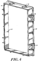
- Each spacer frame 16 is a generally rectangular frame with a short and outwardly facing perimeter wall 62.
- strengthening ribs 64 generally located at several locations on the exterior of the horizontally extending perimeter wall 62.
- fastener brackets 66 are also included on the exterior of the horizontally extending perimeter wall 62.
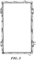
- the outer wall 62 has matching tongues 74 (see Fig. 4) and grooves 76 (see Fig. 5) in the front and rear of the spacer respectively so that adjacent spacer frames 16 can be more securely lined up in a nesting relation and be resistant to lateral movement.
- the assembly of the unit 10 is accomplished by a variety of threaded bolts 69, nuts 72 and posts 28a and 28b. Alternate levels of holes 68 and nut capturing slots 70 of the exterior frames 12, 14 and the spacer brackets 66 are used to assemble the unit 10.
- the outside exterior posts 28a (see Figs. 1 and 6) have a square base 78 to fit into the square hole 26 through the outside exterior frame 12 and have an interior threaded hole 80 in the square base 78 into which a bolt 69 can be threaded.
- the first spacer frame 16 is connected to the exterior frame 14 by a bolt 69 threaded into the post's interior threaded hole 80.
- the next spacer frame 16 (if one is necessary) is connected by a nut 72 and bolt 69, using the alternate level of connecting holes 68 and nut slots 70 of the brackets 66.
- the inside exterior frame 12 is connected.
- Four posts 28b (see Figs. 1 and 7) similar to the ones 28a on the outside are used, except that each has a hole 82 entirely through it and a long bolt 84 is passed through the post 28b and threaded to a nut 72 in one of the slots 70.
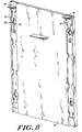
- a security panel 86 (see Figs. 1 and 8) is shown in position to be affixed to the outside exterior frame 14.
- the four posts 28a projecting from the frame 14 have circumferential slots 88.
- the security 86 panel has elongated slots 90 that correspond to the location of the posts 28a.
- the panel 86 is also of a size to fit into the recess formed by the frame 14.
- a pair of metal slides 92 is captured in the panel 86.
- Each slide 92 includes tabs 94 to grasp to move the slide 92, and two keyhole shaped holes 96 for capturing the posts 28b by engaging the circumferential slots 88.
- the slides 92 When the slides 92 are pushed up, the lower, larger portion of the key hole 96 allows the panel 86 to be firmly placed against the frame 14 in a horizontal motion. Pushing down the slides 92 by use of the tabs 94 moves the narrower portion of the keyhole 96 down to engage the circumferential slots 88 of the posts 28b. With the slides 92 in the lower position, the slides 92 are captured by the circumferential slots 88 in the posts 28b and the panel 86 is fixed in position.
- the lower, larger portion of the slider keyhole 96 has an edge 100 that is slightly displaced so that it will not engage the post circumferential slots 88 and interfere with easy removal of the panel 86.
- the security panel 86 is shown on the outside of the assembled unit 10, where it may be mounted on outside posts 28a. When used in that way, its main function is to secure the pet door against the entry of pets or animals.
- the security panel 86 can be easily removed by someone outside a building, in that case.
- the security panel 86 may be mounted on the inside of the assembled unit, mounted on inside posts 28b. There, it may not be removed by someone from outside the door or wall, and provides the desired security.
- Fig. 9 shows an embodiment of the invention in which both exterior frames are flap-bearing frames 12.
- the view is similar to that of Fig. 3, and similar pieces have the same reference numerals as in Fig. 3.
- the assembly shown in Fig. 9 shows three spacers 16, two flap-bearing frames 12, and two flaps 18.
- the two flaps 18 provide an insulating air space 98 between them, and are therefore extremely useful for buildings where extreme weather conditions may prevail.
Landscapes
- Life Sciences & Earth Sciences (AREA)
- Engineering & Computer Science (AREA)
- Environmental Sciences (AREA)
- Mechanical Engineering (AREA)
- Structural Engineering (AREA)
- Animal Behavior & Ethology (AREA)
- Zoology (AREA)
- Animal Husbandry (AREA)
- Biodiversity & Conservation Biology (AREA)
- Civil Engineering (AREA)
- Housing For Livestock And Birds (AREA)
- Door And Window Frames Mounted To Openings (AREA)
- Lock And Its Accessories (AREA)
- Bay Windows, Entrances, And Structural Adjustments Related Thereto (AREA)
Applications Claiming Priority (3)
| Application Number | Priority Date | Filing Date | Title |
|---|---|---|---|
| US07/776,664 US5287654A (en) | 1991-10-15 | 1991-10-15 | Pet access door frame modular unit |
| US776664 | 1991-10-15 | ||
| PCT/US1992/008766 WO1993008362A1 (en) | 1991-10-15 | 1992-10-14 | Pet access door frame modular unit |
Publications (3)
| Publication Number | Publication Date |
|---|---|
| EP0562089A1 EP0562089A1 (en) | 1993-09-29 |
| EP0562089A4 EP0562089A4 (enExample) | 1994-03-23 |
| EP0562089B1 true EP0562089B1 (en) | 1997-02-12 |
Family
ID=25108056
Family Applications (1)
| Application Number | Title | Priority Date | Filing Date |
|---|---|---|---|
| EP92921772A Expired - Lifetime EP0562089B1 (en) | 1991-10-15 | 1992-10-14 | Pet access door frame modular unit |
Country Status (7)
| Country | Link |
|---|---|
| US (1) | US5287654A (enExample) |
| EP (1) | EP0562089B1 (enExample) |
| AT (1) | ATE148931T1 (enExample) |
| AU (1) | AU661433B2 (enExample) |
| CA (1) | CA2098490C (enExample) |
| DE (1) | DE69217478T2 (enExample) |
| WO (1) | WO1993008362A1 (enExample) |
Families Citing this family (51)
| Publication number | Priority date | Publication date | Assignee | Title |
|---|---|---|---|---|
| US5406748A (en) * | 1994-04-08 | 1995-04-18 | Davlantes; George N. | Vertically movable pet door flap |
| US5518175A (en) * | 1994-11-10 | 1996-05-21 | Yeremian; Noubar | Mail slot mounting assembly |
| USD378542S (en) * | 1996-01-04 | 1997-03-18 | Davlantes George N | Pet door locking frame |
| USD384422S (en) * | 1996-01-18 | 1997-09-30 | Davlantes George N | Pet door security cover |
| USD378541S (en) * | 1996-01-24 | 1997-03-18 | Davlantes George N | Pet door security cover |
| USD378543S (en) * | 1996-01-24 | 1997-03-18 | Davlantes George N | Pet door flap frame |
| US5735079A (en) * | 1996-02-01 | 1998-04-07 | Davlantes; George N. | Pet door assembly |
| US5946856A (en) * | 1996-02-01 | 1999-09-07 | Davlantes; George N. | Pet door having a security cover |
| US5782037A (en) * | 1996-02-01 | 1998-07-21 | Davlantes; George N. | Pet door having a security cover |
| US5657592A (en) * | 1996-02-01 | 1997-08-19 | Davlantes; George N. | Pet door having a centrally mounted door flap |
| USD392047S (en) | 1996-07-09 | 1998-03-10 | Davlantes George N | Pet door locking frame |
| USD387179S (en) * | 1996-09-06 | 1997-12-02 | Davlantes George N | Pet door security cover |
| US6581668B1 (en) * | 2001-01-26 | 2003-06-24 | Keven W. Oakley | Window frame for a fence |
| CA2382606A1 (en) * | 2002-04-18 | 2003-10-18 | Normand Savard | Easy to use glass retaining system |
| CA2382661A1 (en) * | 2002-04-19 | 2003-10-19 | Canimex Inc. | Easy clip in/clip out window frame system |
| US6691483B2 (en) * | 2002-06-21 | 2004-02-17 | E. Alan Lethers | Adjustable pet door |
| US7207141B2 (en) * | 2004-09-10 | 2007-04-24 | Accession, Inc. | Sliding door insert for portable pet portal |
| US7814956B2 (en) * | 2004-11-18 | 2010-10-19 | Patio Pacific, Inc. | Pet door |
| RU2007123152A (ru) * | 2004-11-23 | 2008-12-27 | Клэсси Кастом Инк. (Us) | Дверь для домашних животных со съемными декоративными рамками |
| GB0427317D0 (en) * | 2004-12-14 | 2005-01-19 | Mcdermott Peter | Modified pet flap arrangements |
| AU2006200588B2 (en) * | 2005-02-14 | 2011-09-15 | Malcolm Robert Christie | A pet door assembly |
| US7284502B1 (en) | 2005-03-25 | 2007-10-23 | Jill Dotter | Methods and apparatus for a pet door decorative panel system |
| US20070169426A1 (en) * | 2006-01-25 | 2007-07-26 | Allen David F | Window template and art viewer |
| US20070204514A1 (en) * | 2006-03-02 | 2007-09-06 | Radio Systems Corporation | Tunnel/wall unit |
| US7913454B2 (en) * | 2008-04-16 | 2011-03-29 | Accession, Inc. | Portable pet portal with three-position flap assembly |
| US8567137B2 (en) * | 2009-01-12 | 2013-10-29 | Accession, Inc. | Pet door panel storm window |
| US8333037B2 (en) * | 2009-04-28 | 2012-12-18 | Accession, Inc. | Pet door module with integral security panel and cassette portal |
| US8434264B2 (en) * | 2010-03-11 | 2013-05-07 | Radio Systems Corporation | Animal door having an adjustable height |
| US9464476B2 (en) | 2012-05-15 | 2016-10-11 | Radio Systems Corporation | Wall entry tunnel for a pet door |
| US8959850B2 (en) * | 2012-05-15 | 2015-02-24 | Radio Systems Corporation | Wall entry tunnel for a pet door |
| US9926737B2 (en) * | 2013-01-04 | 2018-03-27 | Samuel Solomon Wanjohi | Delivery door |
| USD743051S1 (en) * | 2013-12-09 | 2015-11-10 | Dean Edward Swensson | Gate |
| US9745795B2 (en) * | 2014-08-14 | 2017-08-29 | Nan Dao Engineering Corp. | Inflatable flood barrier |
| US9750201B2 (en) * | 2014-11-07 | 2017-09-05 | William A. Brown | Expandable tree protection device |
| US9915093B2 (en) * | 2015-08-06 | 2018-03-13 | North States Industries, Inc. | Security gate |
| CN105507779B (zh) * | 2016-01-29 | 2017-06-30 | 广州市钢将军门业有限公司 | 一种防火门 |
| US10619389B2 (en) | 2016-12-20 | 2020-04-14 | Radio Systems Corporation | Pet door having insulating flap |
| USD901720S1 (en) * | 2017-07-11 | 2020-11-10 | Lisa N. Harrington | Pet door |
| US10750714B2 (en) | 2017-08-18 | 2020-08-25 | Radio Systems Corporation | Electronic pet door |
| US10941611B2 (en) | 2017-08-18 | 2021-03-09 | Radio Systems Corporation | Pet door |
| US10413106B1 (en) * | 2019-03-15 | 2019-09-17 | Philip Valeriano | Package door for a garage door |
| US10512351B1 (en) * | 2019-03-15 | 2019-12-24 | Philip Valeriano | Package door for a garage door and package delivery method |
| USD964598S1 (en) * | 2020-05-28 | 2022-09-20 | Shenzhen Fengsheng Pet Products Co., Ltd. | Pet door |
| US11976513B2 (en) | 2020-07-09 | 2024-05-07 | North States Industries, Inc. | Security gate |
| WO2022232234A1 (en) * | 2021-04-27 | 2022-11-03 | Davlantes George N | Pet door assembly and flap |
| USD1011555S1 (en) * | 2021-07-27 | 2024-01-16 | Shenzhen Leshuo Technology Co., Ltd. | Pet door |
| US11530571B1 (en) | 2022-02-09 | 2022-12-20 | In & Out Products LLC | Pet travel door system |
| US20220356754A1 (en) * | 2022-07-22 | 2022-11-10 | Yu LOU | Multi-directional opening flap pet door |
| USD1068112S1 (en) * | 2022-07-26 | 2025-03-25 | Wrm Management Group, Inc. | Crawl space door with frame |
| USD1065592S1 (en) * | 2022-07-26 | 2025-03-04 | Wrm Management Group, Inc. | Crawl space door with frame |
| US12270248B2 (en) * | 2023-03-08 | 2025-04-08 | Marc Pentecost | Pet access tunnel and method of installation |
Family Cites Families (11)
| Publication number | Priority date | Publication date | Assignee | Title |
|---|---|---|---|---|
| US2758646A (en) * | 1952-12-04 | 1956-08-14 | Don D Johnson | Door structure |
| US3797554A (en) * | 1972-06-09 | 1974-03-19 | F Johnson | Pet door structure |
| US3861081A (en) * | 1973-09-20 | 1975-01-21 | Stanley J Maskell | Flood barrier |
| US4047331A (en) * | 1975-10-14 | 1977-09-13 | Davlantes George N | Pet access door panel |
| US4043079A (en) * | 1976-12-02 | 1977-08-23 | Smith Walter E | Automatic latch door apparatus |
| US4370828A (en) * | 1978-06-12 | 1983-02-01 | Miro Carl F | Window frame assembly |
| US4259818A (en) * | 1979-07-31 | 1981-04-07 | Anemostat Products Division, Dynamics Corporation Of America | Tamper-proof window unit |
| US4651793A (en) * | 1982-09-27 | 1987-03-24 | Davlantes George N | Pet door flap with slow moving sill |
| US4730413A (en) * | 1987-01-23 | 1988-03-15 | Nami Products, Inc. | Removable automobile side window |
| US4839989A (en) * | 1988-03-31 | 1989-06-20 | Mcconnell Dale K | Door light |
| US4856575A (en) * | 1988-06-24 | 1989-08-15 | Wells David F | Window assembly for segmented structure |
-
1991
- 1991-10-15 US US07/776,664 patent/US5287654A/en not_active Expired - Fee Related
-
1992
- 1992-10-14 EP EP92921772A patent/EP0562089B1/en not_active Expired - Lifetime
- 1992-10-14 DE DE69217478T patent/DE69217478T2/de not_active Expired - Fee Related
- 1992-10-14 CA CA002098490A patent/CA2098490C/en not_active Expired - Fee Related
- 1992-10-14 WO PCT/US1992/008766 patent/WO1993008362A1/en not_active Ceased
- 1992-10-14 AT AT92921772T patent/ATE148931T1/de not_active IP Right Cessation
-
1994
- 1994-07-20 AU AU67572/94A patent/AU661433B2/en not_active Ceased
Also Published As
| Publication number | Publication date |
|---|---|
| AU657657B2 (en) | 1995-03-16 |
| US5287654A (en) | 1994-02-22 |
| AU2864192A (en) | 1993-05-21 |
| EP0562089A1 (en) | 1993-09-29 |
| DE69217478T2 (de) | 1997-09-11 |
| AU6757294A (en) | 1994-09-22 |
| ATE148931T1 (de) | 1997-02-15 |
| EP0562089A4 (enExample) | 1994-03-23 |
| CA2098490A1 (en) | 1993-04-16 |
| DE69217478D1 (de) | 1997-03-27 |
| CA2098490C (en) | 2004-01-27 |
| AU661433B2 (en) | 1995-07-20 |
| WO1993008362A1 (en) | 1993-04-29 |
Similar Documents
| Publication | Publication Date | Title |
|---|---|---|
| EP0562089B1 (en) | Pet access door frame modular unit | |
| US5269097A (en) | Pet access door frame modular unit | |
| US4760872A (en) | Security pet door | |
| US4677791A (en) | Adjustable gate for doorways | |
| US5956920A (en) | Modular post cladding element, post cladding assembly, and method of cladding a post | |
| US5347775A (en) | Hurricane shutters for windows | |
| US7427055B2 (en) | Mounting bracket and snap-on cover assembly for use therewith | |
| US5337697A (en) | Feline window perch | |
| US3985174A (en) | Pet door | |
| US6003583A (en) | Door opening screening system | |
| US4870908A (en) | Office space dividing system | |
| US20030127575A1 (en) | Fence rail cap bracket assembly | |
| EP2902001B1 (en) | Portable spa construction | |
| US6668487B2 (en) | System and method for applying an animal access door to an inclined surface | |
| US7178300B2 (en) | Latch-type tile mounting system | |
| US4552094A (en) | Horse stall construction | |
| AU657657C (en) | Pet access door frame modular unit | |
| JPS60476Y2 (ja) | 格子止め金具 | |
| RU2038457C1 (ru) | Дверная коробка | |
| JP2002097861A (ja) | ペット用ドアパネル | |
| KR100466344B1 (ko) | 거실 확장장치 | |
| JP3035184U (ja) | ドアストッパー | |
| JPH0715969Y2 (ja) | 組立家屋 | |
| GB2187780A (en) | Improvements in fly doors | |
| CA1074561A (en) | Pet or doll house |
Legal Events
| Date | Code | Title | Description |
|---|---|---|---|
| PUAI | Public reference made under article 153(3) epc to a published international application that has entered the european phase |
Free format text: ORIGINAL CODE: 0009012 |
|
| AK | Designated contracting states |
Kind code of ref document: A1 Designated state(s): AT BE CH DE DK ES FR GB GR IE IT LI LU MC NL SE |
|
| 17P | Request for examination filed |
Effective date: 19931016 |
|
| RHK1 | Main classification (correction) |
Ipc: E06B 7/32 |
|
| A4 | Supplementary search report drawn up and despatched |
Effective date: 19940204 |
|
| AK | Designated contracting states |
Kind code of ref document: A4 Designated state(s): AT BE CH DE DK ES FR GB GR IE IT LI LU MC NL SE |
|
| 17Q | First examination report despatched |
Effective date: 19950828 |
|
| GRAG | Despatch of communication of intention to grant |
Free format text: ORIGINAL CODE: EPIDOS AGRA |
|
| GRAH | Despatch of communication of intention to grant a patent |
Free format text: ORIGINAL CODE: EPIDOS IGRA |
|
| GRAH | Despatch of communication of intention to grant a patent |
Free format text: ORIGINAL CODE: EPIDOS IGRA |
|
| GRAA | (expected) grant |
Free format text: ORIGINAL CODE: 0009210 |
|
| AK | Designated contracting states |
Kind code of ref document: B1 Designated state(s): AT BE CH DE DK ES FR GB GR IE IT LI LU MC NL SE |
|
| PG25 | Lapsed in a contracting state [announced via postgrant information from national office to epo] |
Ref country code: LI Effective date: 19970212 Ref country code: GR Free format text: LAPSE BECAUSE OF FAILURE TO SUBMIT A TRANSLATION OF THE DESCRIPTION OR TO PAY THE FEE WITHIN THE PRESCRIBED TIME-LIMIT Effective date: 19970212 Ref country code: ES Free format text: THE PATENT HAS BEEN ANNULLED BY A DECISION OF A NATIONAL AUTHORITY Effective date: 19970212 Ref country code: DK Effective date: 19970212 Ref country code: CH Effective date: 19970212 Ref country code: BE Effective date: 19970212 Ref country code: AT Effective date: 19970212 |
|
| REF | Corresponds to: |
Ref document number: 148931 Country of ref document: AT Date of ref document: 19970215 Kind code of ref document: T |
|
| REG | Reference to a national code |
Ref country code: CH Ref legal event code: EP |
|
| REF | Corresponds to: |
Ref document number: 69217478 Country of ref document: DE Date of ref document: 19970327 |
|
| ITF | It: translation for a ep patent filed | ||
| REG | Reference to a national code |
Ref country code: IE Ref legal event code: FG4D Free format text: 72022 |
|
| PG25 | Lapsed in a contracting state [announced via postgrant information from national office to epo] |
Ref country code: SE Effective date: 19970512 |
|
| ET | Fr: translation filed | ||
| REG | Reference to a national code |
Ref country code: CH Ref legal event code: PL |
|
| PG25 | Lapsed in a contracting state [announced via postgrant information from national office to epo] |
Ref country code: LU Free format text: LAPSE BECAUSE OF NON-PAYMENT OF DUE FEES Effective date: 19971014 Ref country code: IE Free format text: LAPSE BECAUSE OF NON-PAYMENT OF DUE FEES Effective date: 19971014 |
|
| PLBE | No opposition filed within time limit |
Free format text: ORIGINAL CODE: 0009261 |
|
| STAA | Information on the status of an ep patent application or granted ep patent |
Free format text: STATUS: NO OPPOSITION FILED WITHIN TIME LIMIT |
|
| 26N | No opposition filed | ||
| PG25 | Lapsed in a contracting state [announced via postgrant information from national office to epo] |
Ref country code: MC Free format text: LAPSE BECAUSE OF NON-PAYMENT OF DUE FEES Effective date: 19980430 |
|
| REG | Reference to a national code |
Ref country code: GB Ref legal event code: IF02 |
|
| PGFP | Annual fee paid to national office [announced via postgrant information from national office to epo] |
Ref country code: FR Payment date: 20040921 Year of fee payment: 13 |
|
| PGFP | Annual fee paid to national office [announced via postgrant information from national office to epo] |
Ref country code: NL Payment date: 20040923 Year of fee payment: 13 |
|
| PGFP | Annual fee paid to national office [announced via postgrant information from national office to epo] |
Ref country code: GB Payment date: 20040927 Year of fee payment: 13 |
|
| PGFP | Annual fee paid to national office [announced via postgrant information from national office to epo] |
Ref country code: DE Payment date: 20041029 Year of fee payment: 13 |
|
| PG25 | Lapsed in a contracting state [announced via postgrant information from national office to epo] |
Ref country code: IT Free format text: LAPSE BECAUSE OF NON-PAYMENT OF DUE FEES;WARNING: LAPSES OF ITALIAN PATENTS WITH EFFECTIVE DATE BEFORE 2007 MAY HAVE OCCURRED AT ANY TIME BEFORE 2007. THE CORRECT EFFECTIVE DATE MAY BE DIFFERENT FROM THE ONE RECORDED. Effective date: 20051014 Ref country code: GB Free format text: LAPSE BECAUSE OF NON-PAYMENT OF DUE FEES Effective date: 20051014 |
|
| PG25 | Lapsed in a contracting state [announced via postgrant information from national office to epo] |
Ref country code: NL Free format text: LAPSE BECAUSE OF NON-PAYMENT OF DUE FEES Effective date: 20060501 |
|
| PG25 | Lapsed in a contracting state [announced via postgrant information from national office to epo] |
Ref country code: DE Free format text: LAPSE BECAUSE OF NON-PAYMENT OF DUE FEES Effective date: 20060503 |
|
| GBPC | Gb: european patent ceased through non-payment of renewal fee |
Effective date: 20051014 |
|
| PG25 | Lapsed in a contracting state [announced via postgrant information from national office to epo] |
Ref country code: FR Free format text: LAPSE BECAUSE OF NON-PAYMENT OF DUE FEES Effective date: 20060630 |
|
| NLV4 | Nl: lapsed or anulled due to non-payment of the annual fee |
Effective date: 20060501 |
|
| REG | Reference to a national code |
Ref country code: FR Ref legal event code: ST Effective date: 20060630 |