EP0559335A2 - Hybrider Gasgenerator - Google Patents
Hybrider Gasgenerator Download PDFInfo
- Publication number
- EP0559335A2 EP0559335A2 EP93300926A EP93300926A EP0559335A2 EP 0559335 A2 EP0559335 A2 EP 0559335A2 EP 93300926 A EP93300926 A EP 93300926A EP 93300926 A EP93300926 A EP 93300926A EP 0559335 A2 EP0559335 A2 EP 0559335A2
- Authority
- EP
- European Patent Office
- Prior art keywords
- pyrotechnic
- gas
- inflator
- pyrotechnic material
- sheet
- Prior art date
- Legal status (The legal status is an assumption and is not a legal conclusion. Google has not performed a legal analysis and makes no representation as to the accuracy of the status listed.)
- Granted
Links
- 239000007789 gas Substances 0.000 claims abstract description 64
- 239000000463 material Substances 0.000 claims abstract description 64
- 230000001590 oxidative effect Effects 0.000 claims abstract description 10
- 229920001343 polytetrafluoroethylene Polymers 0.000 claims abstract description 9
- 239000004810 polytetrafluoroethylene Substances 0.000 claims abstract description 9
- FYYHWMGAXLPEAU-UHFFFAOYSA-N Magnesium Chemical compound [Mg] FYYHWMGAXLPEAU-UHFFFAOYSA-N 0.000 claims abstract description 6
- 238000010438 heat treatment Methods 0.000 claims abstract description 6
- 229910052749 magnesium Inorganic materials 0.000 claims abstract description 6
- 239000011777 magnesium Substances 0.000 claims abstract description 6
- -1 polytetrafluoroethylene Polymers 0.000 claims abstract description 6
- 239000000758 substrate Substances 0.000 claims abstract description 6
- 229910052751 metal Inorganic materials 0.000 claims description 12
- 239000002184 metal Substances 0.000 claims description 12
- 229920001577 copolymer Polymers 0.000 claims description 10
- BQCIDUSAKPWEOX-UHFFFAOYSA-N 1,1-Difluoroethene Chemical compound FC(F)=C BQCIDUSAKPWEOX-UHFFFAOYSA-N 0.000 claims description 8
- 230000000977 initiatory effect Effects 0.000 claims description 7
- 239000000203 mixture Substances 0.000 claims description 7
- HCDGVLDPFQMKDK-UHFFFAOYSA-N hexafluoropropylene Chemical group FC(F)=C(F)C(F)(F)F HCDGVLDPFQMKDK-UHFFFAOYSA-N 0.000 claims description 5
- IJGRMHOSHXDMSA-UHFFFAOYSA-N Atomic nitrogen Chemical compound N#N IJGRMHOSHXDMSA-UHFFFAOYSA-N 0.000 claims description 4
- 229920001519 homopolymer Polymers 0.000 claims description 4
- 229920000642 polymer Polymers 0.000 claims description 4
- 229910045601 alloy Inorganic materials 0.000 claims description 3
- 239000000956 alloy Substances 0.000 claims description 3
- OYPRJOBELJOOCE-UHFFFAOYSA-N Calcium Chemical compound [Ca] OYPRJOBELJOOCE-UHFFFAOYSA-N 0.000 claims description 2
- DGAQECJNVWCQMB-PUAWFVPOSA-M Ilexoside XXIX Chemical compound C[C@@H]1CC[C@@]2(CC[C@@]3(C(=CC[C@H]4[C@]3(CC[C@@H]5[C@@]4(CC[C@@H](C5(C)C)OS(=O)(=O)[O-])C)C)[C@@H]2[C@]1(C)O)C)C(=O)O[C@H]6[C@@H]([C@H]([C@@H]([C@H](O6)CO)O)O)O.[Na+] DGAQECJNVWCQMB-PUAWFVPOSA-M 0.000 claims description 2
- WHXSMMKQMYFTQS-UHFFFAOYSA-N Lithium Chemical compound [Li] WHXSMMKQMYFTQS-UHFFFAOYSA-N 0.000 claims description 2
- NINIDFKCEFEMDL-UHFFFAOYSA-N Sulfur Chemical compound [S] NINIDFKCEFEMDL-UHFFFAOYSA-N 0.000 claims description 2
- 239000005864 Sulphur Substances 0.000 claims description 2
- RTAQQCXQSZGOHL-UHFFFAOYSA-N Titanium Chemical compound [Ti] RTAQQCXQSZGOHL-UHFFFAOYSA-N 0.000 claims description 2
- XSTXAVWGXDQKEL-UHFFFAOYSA-N Trichloroethylene Chemical group ClC=C(Cl)Cl XSTXAVWGXDQKEL-UHFFFAOYSA-N 0.000 claims description 2
- QCWXUUIWCKQGHC-UHFFFAOYSA-N Zirconium Chemical compound [Zr] QCWXUUIWCKQGHC-UHFFFAOYSA-N 0.000 claims description 2
- 229910052782 aluminium Inorganic materials 0.000 claims description 2
- 239000004411 aluminium Substances 0.000 claims description 2
- XAGFODPZIPBFFR-UHFFFAOYSA-N aluminium Chemical compound [Al] XAGFODPZIPBFFR-UHFFFAOYSA-N 0.000 claims description 2
- QVGXLLKOCUKJST-UHFFFAOYSA-N atomic oxygen Chemical compound [O] QVGXLLKOCUKJST-UHFFFAOYSA-N 0.000 claims description 2
- 229910052788 barium Inorganic materials 0.000 claims description 2
- DSAJWYNOEDNPEQ-UHFFFAOYSA-N barium atom Chemical compound [Ba] DSAJWYNOEDNPEQ-UHFFFAOYSA-N 0.000 claims description 2
- 229910052790 beryllium Inorganic materials 0.000 claims description 2
- ATBAMAFKBVZNFJ-UHFFFAOYSA-N beryllium atom Chemical compound [Be] ATBAMAFKBVZNFJ-UHFFFAOYSA-N 0.000 claims description 2
- 229910052791 calcium Inorganic materials 0.000 claims description 2
- 239000011575 calcium Substances 0.000 claims description 2
- UUAGAQFQZIEFAH-UHFFFAOYSA-N chlorotrifluoroethylene Chemical group FC(F)=C(F)Cl UUAGAQFQZIEFAH-UHFFFAOYSA-N 0.000 claims description 2
- 229910052736 halogen Inorganic materials 0.000 claims description 2
- 150000002367 halogens Chemical class 0.000 claims description 2
- BHEPBYXIRTUNPN-UHFFFAOYSA-N hydridophosphorus(.) (triplet) Chemical compound [PH] BHEPBYXIRTUNPN-UHFFFAOYSA-N 0.000 claims description 2
- 229910052744 lithium Inorganic materials 0.000 claims description 2
- 229910052757 nitrogen Inorganic materials 0.000 claims description 2
- 239000001301 oxygen Substances 0.000 claims description 2
- 229910052760 oxygen Inorganic materials 0.000 claims description 2
- 238000009527 percussion Methods 0.000 claims description 2
- 229910052708 sodium Inorganic materials 0.000 claims description 2
- 239000011734 sodium Substances 0.000 claims description 2
- 229910052712 strontium Inorganic materials 0.000 claims description 2
- CIOAGBVUUVVLOB-UHFFFAOYSA-N strontium atom Chemical compound [Sr] CIOAGBVUUVVLOB-UHFFFAOYSA-N 0.000 claims description 2
- BFKJFAAPBSQJPD-UHFFFAOYSA-N tetrafluoroethene Chemical group FC(F)=C(F)F BFKJFAAPBSQJPD-UHFFFAOYSA-N 0.000 claims description 2
- 229910052719 titanium Inorganic materials 0.000 claims description 2
- 239000010936 titanium Substances 0.000 claims description 2
- UBOXGVDOUJQMTN-UHFFFAOYSA-N trichloroethylene Natural products ClCC(Cl)Cl UBOXGVDOUJQMTN-UHFFFAOYSA-N 0.000 claims description 2
- 229910052726 zirconium Inorganic materials 0.000 claims description 2
- 239000011261 inert gas Substances 0.000 abstract description 8
- 238000010276 construction Methods 0.000 abstract description 4
- 239000012265 solid product Substances 0.000 abstract description 3
- 239000010419 fine particle Substances 0.000 abstract 1
- 230000009172 bursting Effects 0.000 description 7
- XKRFYHLGVUSROY-UHFFFAOYSA-N Argon Chemical compound [Ar] XKRFYHLGVUSROY-UHFFFAOYSA-N 0.000 description 4
- PXIPVTKHYLBLMZ-UHFFFAOYSA-N Sodium azide Chemical compound [Na+].[N-]=[N+]=[N-] PXIPVTKHYLBLMZ-UHFFFAOYSA-N 0.000 description 4
- 229940058401 polytetrafluoroethylene Drugs 0.000 description 4
- 238000007789 sealing Methods 0.000 description 4
- 239000004020 conductor Substances 0.000 description 3
- 239000000047 product Substances 0.000 description 3
- 239000007787 solid Substances 0.000 description 3
- 229910001209 Low-carbon steel Inorganic materials 0.000 description 2
- 229910052786 argon Inorganic materials 0.000 description 2
- 238000005474 detonation Methods 0.000 description 2
- 229920002313 fluoropolymer Polymers 0.000 description 2
- 239000004811 fluoropolymer Substances 0.000 description 2
- 239000001307 helium Substances 0.000 description 2
- 229910052734 helium Inorganic materials 0.000 description 2
- SWQJXJOGLNCZEY-UHFFFAOYSA-N helium atom Chemical compound [He] SWQJXJOGLNCZEY-UHFFFAOYSA-N 0.000 description 2
- 238000012986 modification Methods 0.000 description 2
- 230000004048 modification Effects 0.000 description 2
- 239000002245 particle Substances 0.000 description 2
- 230000000717 retained effect Effects 0.000 description 2
- 125000006850 spacer group Chemical group 0.000 description 2
- 239000010935 stainless steel Substances 0.000 description 2
- 229910001220 stainless steel Inorganic materials 0.000 description 2
- 241000239290 Araneae Species 0.000 description 1
- PXGOKWXKJXAPGV-UHFFFAOYSA-N Fluorine Chemical compound FF PXGOKWXKJXAPGV-UHFFFAOYSA-N 0.000 description 1
- AFCARXCZXQIEQB-UHFFFAOYSA-N N-[3-oxo-3-(2,4,6,7-tetrahydrotriazolo[4,5-c]pyridin-5-yl)propyl]-2-[[3-(trifluoromethoxy)phenyl]methylamino]pyrimidine-5-carboxamide Chemical compound O=C(CCNC(=O)C=1C=NC(=NC=1)NCC1=CC(=CC=C1)OC(F)(F)F)N1CC2=C(CC1)NN=N2 AFCARXCZXQIEQB-UHFFFAOYSA-N 0.000 description 1
- 230000004913 activation Effects 0.000 description 1
- 239000012190 activator Substances 0.000 description 1
- 230000003190 augmentative effect Effects 0.000 description 1
- 238000006243 chemical reaction Methods 0.000 description 1
- 238000002485 combustion reaction Methods 0.000 description 1
- 230000001419 dependent effect Effects 0.000 description 1
- 238000010586 diagram Methods 0.000 description 1
- 230000000694 effects Effects 0.000 description 1
- 229910052731 fluorine Inorganic materials 0.000 description 1
- 239000011737 fluorine Substances 0.000 description 1
- 239000011521 glass Substances 0.000 description 1
- 230000001473 noxious effect Effects 0.000 description 1
- 239000003380 propellant Substances 0.000 description 1
- 239000004065 semiconductor Substances 0.000 description 1
- 238000013022 venting Methods 0.000 description 1
- 238000003466 welding Methods 0.000 description 1
Images


Classifications
-
- B—PERFORMING OPERATIONS; TRANSPORTING
- B60—VEHICLES IN GENERAL
- B60R—VEHICLES, VEHICLE FITTINGS, OR VEHICLE PARTS, NOT OTHERWISE PROVIDED FOR
- B60R21/00—Arrangements or fittings on vehicles for protecting or preventing injuries to occupants or pedestrians in case of accidents or other traffic risks
- B60R21/02—Occupant safety arrangements or fittings, e.g. crash pads
- B60R21/16—Inflatable occupant restraints or confinements designed to inflate upon impact or impending impact, e.g. air bags
- B60R21/26—Inflatable occupant restraints or confinements designed to inflate upon impact or impending impact, e.g. air bags characterised by the inflation fluid source or means to control inflation fluid flow
- B60R21/268—Inflatable occupant restraints or confinements designed to inflate upon impact or impending impact, e.g. air bags characterised by the inflation fluid source or means to control inflation fluid flow using instantaneous release of stored pressurised gas
- B60R21/272—Inflatable occupant restraints or confinements designed to inflate upon impact or impending impact, e.g. air bags characterised by the inflation fluid source or means to control inflation fluid flow using instantaneous release of stored pressurised gas with means for increasing the pressure of the gas just before or during liberation, e.g. hybrid inflators
Definitions
- This invention relates to a hybrid inflator of the kind used to inflate an occupant restraint cushion or bag in safety apparatus in motorised vehicles when the vehicle is arrested in a collision.
- the invention also includes a heating element for a hybrid inflator.
- Gas bags in restraint systems are inflated by gas from a stored supply of inert gas under high pressure, by gas generated locally from a gas generating pyrotechnic material such as a sodium azide containing composition or by gas derived from the so-called hybrid or augmented gas system comprising stored compressed gas and also a gas and heat generating pyrotechnic material.
- a gas generating pyrotechnic material such as a sodium azide containing composition
- gas derived from the so-called hybrid or augmented gas system comprising stored compressed gas and also a gas and heat generating pyrotechnic material.
- the generated hot gas mixes with and expands or increases the pressure of the stored compressed gas. Consequently, the amount of gas required to be stored is substantially less than in systems relying only on stored gas and the gas storage pressure and/or the overall size of the inflator is generally substantially reduced.
- the hybrid system is bulkier than the system using only a pyrotechnic material, it is often preferred as it produces less solids and noxious gases in the
- Typical hybrid inflators are described in United Kingdom patent specification no. 1408530 and in United States patent specifications nos. 4131300; 5022674; 5031932 and 5033772.
- hybrid inflators used hitherto the pyrotechnic hot gas generating composition is contained in a separate pressure vessel which is usually placed within the pressure vessel containing the stored pressurised gas and both containers are arranged to deliver gas to a mixing zone before the mixed inflation gases pass into the bag.
- This arrangement of apparatus is complicated, requires accurately constructed flow control devices and is expensive.
- a further disadvantage of a hybrid inflator is the relatively large particle size of the solid products from the pyrotechnic composition which products can cause blockage of gas delivery passages and are relatively inefficient in transferring heat to the stored gas.
- An object of this invention is to provide a hybrid inflator which is simpler and cheaper to construct than those employed hitherto.
- a further object is to provide a hybrid inflator wherein the efficiency of heat transfer from the pyrotechnic material to the stored gas is substantially improved.
- a hybrid inflator for a vehicle occupant restraint gas bag comprises a stored supply of gas under pressure in a gas storage vessel having a sealed exit leading to the gas bag; a heat generating pyrotechnic material effective to heat and expand the said stored gas; initiation means to ignite the pyrotechnic material and means to open the sealed exit, characterised in that the heat generating pyrotechnic material comprises pyrotechnic material in sheet form.
- the selected pyrotechnic material may be located separately from the vessel containing the stored gas and the hot products of the pyrotechnic material mixed with the stored gas in a mixing zone before delivery to the restraint bag.
- the pyrotechnic material be located inside the gas storage vessel and preferably in a thin container or in direct contact with the stored gas. Such an arrangement is possible as the sheeted pyrotechnic material is unaffected by the stored gas and withstands the high gas pressure.
- the sheeted pyrotechnic material may be in flat form, for example, one or more flat strips or discs which may be maintained in spaced relationship to facilitate rapid combustion.
- the sheet may be folded, wrinkled, pleated, corrugated, fluted or wrapped into any convenient shape for disposal inside the pressure vessel.
- the pyrotechnic sheet may be wrapped around a central rigid former, for example a solid rod or a solid, perforated or mesh tube.
- the sheet may optionally be wrapped around a charge of pyrotechnic material such as a sodium azide composition or the former may contain such a charge.
- the sheet may be wrapped as a single or multiple wrap applied, for example, as a spirally or helically wrapped film.
- the wrapped sheet may advantageously be slit through at one or more positions to provide venting passages and may optionally be placed inside a perforated tubular housing.
- the use of a former prevents collapse of the pyrotechnic sheet under the initial ignition impulse from the igniter thereby ensuring that the pyrotechnic material is presented to the igniter in a suitable manner for obtaining efficient ignition.
- the stored gas is preferably an inert gas, for example argon, which may advantageously contain a small percentage, for example 1-2% of helium to facilitate leak testing.
- the gas may conveniently be stored at a pressure of about 3000psi and the volume of gas may conveniently be from 0.1 to 2.0 litres.
- the sheeted pyrotechnic material may comprise a carrier sheet coated with a layer of pyrotechnic material, a specially preferred pyrotechnic material comprising a substrate of an oxidizing polymeric film having a layer of oxidizable material on at least a portion of at least one surface, the polymeric film and the oxidizable material being conjointly capably of reacting together exothermically on ignition.
- the polymeric film is coated on both sides with oxidizable material.
- a particularly preferred pyrotechnic film layer is described in PCT International Publications Nos. WO 90/10611 and WO 90/10724.
- the oxidizing polymeric film described therein contains atoms chemically bound therein selected from the group consisting of halogens (especially fluorine), oxygen, sulphur, nitrogen and phosphorous.
- One preferred film layer is made from fluoropolymer such as polytetrafluoro-ethylene (PTFE) which produces high energy pyrotechnic films
- fluoropolymer such as polytetrafluoro-ethylene (PTFE) which produces high energy pyrotechnic films
- suitable polymeric films include those made from polyhexafluoropropylene, copolymers of vinylidene fluoride and hexafluoropropylene, copolymers of tetrafluoroethylene and perfluropropylene, copolymers of chlorotrifluoroethylene and vinylidene fluoride, homopolymers of perfluoropropylene and its copolymers with vinylidene fluoride, trichloroethylene homopolymer and its copolymers with vinylidene fluoride, and mixtures of two or more of such polymers with each other or with PTFE.
- PTFE polytetrafluoro-ethylene
- the oxidizable material is advantageously vapour-deposited on the film layer and may suitably comprise a metal selected from the group consisting of lithium, sodium, magnesium, beryllium, calcium, strontium, barium, aluminium, titanium, zirconium, and alloys thereof.
- a most preferred metal is magnesium or an alloy thereof preferably coated on to a fluoropolymer substrate.
- the ratio of metal to the substrate of oxidising polymeric film is substantially stoichiometric or there is a small excess of metal at the location of the film underlying the metal.
- a typical pyrotechnic film comprises a film of polytetrafluoroethylene 3 to 50 microns, (typically 10-50 microns) thick, having vapour-deposited on each side a layer of magnesium 2 to 40 microns (typically 10 microns) thick.
- the reaction equation is (C 2 F 4)n + 2Mg -> 2MgF 2(g) + 2C(s) + 5.98Mj/Kg
- the rate of energy release varies inversely with the thickness of the pyrotechnic film and, accordingly, the thickness may be chosen to attain the desired energy release rate.
- the charge of pyrotechnic material may conveniently be from 2 to 50 grams.
- the initiation means to ignite the pyrotechnic material may be, for example, a squib, an exploding bridge wire, a semi-conductor bridge, a spark discharge, an electric current or a hot wire.
- the initiation means may be arranged to be actuated in response to a collision involving a vehicle containing the inflator. Once initiated, the pyrotechnic film reacts rapidly to generate hot products which heat and expand the stored gas.
- the gas exit from the pressure vessel is conveniently sealed by a frangible element such as a bursting disc or septum.
- the frangible element may be burst by bursting means such as an electric squib fired in response to the vehicle collision and independently of the ignition of the pyrotechnic material, in which case the pressurised gas may be partially released before, or simultaneously with, the ignition of the pyrotechnic material.
- the frangible element may be burst simultaneously with or in response to the ignition of the pyrotechnic material by operation of the initiation means on collision of the vehicle.
- the frangible element may be arranged to burst on the attainment of predetermined conditions of pressure and heat inside the gas storage vessel. In this embodiment the bursting of the frangible element may be effected or facilitated by means of an adjacent heat-sensitive detonator.
- a projectile propelled by the burning of the pyrotechnic material or by the impulse of the initiation means may be driven directly against the frangible element to rupture the element, or the projectile may be driven against a percussion detonation such as an inpact sensitive or stab-sensitive detonator which is arranged, on actuation by the projectile, to rupture the frangible element.
- the invention consists in the use of a heat generating pyrotechnic material in sheet form as the heat generating material in a heating element for a hybrid inflator for a gas bag.
- pyrotechnic sheet as the heat generator in a hybrid inflator for vehicle occupant restraint systems allows the inflator construction to be simplified without sacrificing reliability. There is no longer any need to have a second pressure vessel to contain the pyrotechnic material, nor is there any need for sophisticated flow control devices or mixing chambers.
- the sheeted pyrotechnic material produces solid products of very small particle size which transfer their thermal energy very efficiently to the stored gas. Moreover the violence of the initial energy release from the pyrotechnic material gives more efficient pressure vessel opening than any pyrotechnic material or propellant used hitherto in occupant restraint systems and thus allows the construction of the pressure vessel closures to be simplified.
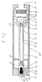
- an inflator designated generally 10 includes a mild steel pressure vessel 11 containing a spirally wrapped charge of pyrotechnic sheet material 12 (heating element) located between two perforated spacer members 13, 14.
- the wrapped pyrotechnic element 12 is slit through with a longitudinal slit 15 to facilitate gas flow on ignition of the pyrotechnic material.
- a metal cased ignitor squib 16 is sealed by welding into an end 17 of the vessel 11, the squib including conductor leads 18 for connection to activator means (not shown), the leads 18 being sealed into the squib in known manner by means of a glass to metal seal.
- a filter element 19 of porous inert material is located in a portion of the vessel 11 at the end 20 opposite to the end 17.
- the end 20 has an exit opening 21 sealed with a stainless steel seating element 22, welded to the vessel 11 at the end 20, the element 22 having an aperture 23 sealed with a bursting disc 24 welded thereto.
- the vessel 11 conveniently has a capacity of 0.1 - 2 litres and is filled with an inert gas conveniently 98% argon and 2% helium by volume at a pressure of about 3000psi.
- the heating element 12 conveniently comprises about 6 to 25 grams of pyrotechnic sheet.
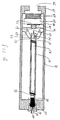
- an inflator designated generally 30 includes a mild steel pressure vessel 31 which is filled with inert gas at a pressure of about 3000 psi.
- the vessel 31 contains a spirally wrapped charge of pyrotechnic sheet material 32 wrapped on a central former 33 and encased in a relatively light metal casing 34.
- One end 35 of casing 34 is fixed in an aperture 36 formed in an end 37 of vessel 31.
- An electric ignitor squib 38 is welded into the end 35 of casing 34 and is sealed into and retained in aperture 36 by a retaining ring 39 which is welded to the vessel 31 and to the metal case of the squib 38.
- the squib 38 has conductor leads 40 for connection to activation means (not shown).
- the other end 41 of the casing 34 is located centrally in the vessel 31 by a spider element 42.
- the end of casing 34 has an external circumferential groove 43 formed therein which defines a tapered or pointed end portion 44 which breaks away from the end 35 of the casing 34 when the charge 32 is ignited and the pressure in the casing 34 exceeds a predetermined value.
- the portion 44 is centred in the vessel 31 by a centering guide element 60 which maintains the axial alignment of the portion 44 after it is broken away from the end 35.
- the second end 45 of the vessel 31 has an exit opening 46 and contains a sealing element 47 at a position which leaves a plenum chamber 48 between the sealing element 47 and the exit opening 45 in which the inflation gases expand before flowing through the opening 46 to a gas bag (not shown).
- a porous inert filter element 49 obturates the opening 46 and is retained in position by an annular spacer element 50.
- the sealing element 47 is a metal annular member which is peripherally welded to the vessel 31 and has a central aperture 51 which is sealed by a thin stainless steel frangible disc 52.
- the embodiment shown in Fig 3 is a modification of the embodiment shown in Fig 2 but having an impact-sensitive detonator 53 in contact with the frangible disc 52, the sealing element 47 being modified to accommodate the disc 52 and the detonator 53.
- the pointed end portion 44 of the casing 34 breaks away at the groove 43 and is projected against and initiates the detonator 53.
- the detonation of detonator 53 immediately bursts the frangible disc 52 and allows the inert gas, which has been heated by the burning of the pyrotechnic charge 32, to flow through the aperture 51, filter 49 and exit opening 46 to inflate a gas bag.
- the embodiment shown in Fig 4 is a modification of the embodiment shown in Fig 3, but the detonator 53 is stab-sensitive instead of impact sensitive.
- the casing 34 is omitted, the central former 33 is hollow and an axially movable element 54 is axially disposed within the former 33.
- One end of the element 54 is located adjacent to the squib 38 and arranged so that on ignition of the squib the element 54 is propelled axially through the former 33 by the impulse of the ignition, the flame from the squib 38 simultaneously igniting the pyrotechnic material 32.
- the other end of the element 54 has a needle point 55 which is axially spaced from detonator 53 but, on ignition of the squib 38, penetrates the detonator 53 to effect bursting of the frangible disc 52 and consequent release of the heated gases to inflate a gas bag.
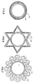
- the pyrotechnic sheet 32 material is wrapped in generally spiral fashion around a central former 33.
- the pyrotechnic sheet 32 of Fig 5 is a flat sheet with the coils being loosely wound or spaced apart.
- the sheeted pyrotechnic material is a fluted sheet and in Fig 7 it is a corrugated sheet.
Landscapes
- Engineering & Computer Science (AREA)
- Mechanical Engineering (AREA)
- Physics & Mathematics (AREA)
- Fluid Mechanics (AREA)
- Air Bags (AREA)
Applications Claiming Priority (2)
| Application Number | Priority Date | Filing Date | Title |
|---|---|---|---|
| GB9204712 | 1992-03-04 | ||
| GB929204712A GB9204712D0 (en) | 1992-03-04 | 1992-03-04 | Hybrid inflator |
Publications (3)
| Publication Number | Publication Date |
|---|---|
| EP0559335A2 true EP0559335A2 (de) | 1993-09-08 |
| EP0559335A3 EP0559335A3 (de) | 1993-09-15 |
| EP0559335B1 EP0559335B1 (de) | 1996-11-20 |
Family
ID=10711510
Family Applications (1)
| Application Number | Title | Priority Date | Filing Date |
|---|---|---|---|
| EP93300926A Expired - Lifetime EP0559335B1 (de) | 1992-03-04 | 1993-02-09 | Hybrider Gasgenerator |
Country Status (8)
| Country | Link |
|---|---|
| US (1) | US5411290A (de) |
| EP (1) | EP0559335B1 (de) |
| JP (1) | JPH0640304A (de) |
| KR (1) | KR930019475A (de) |
| CA (1) | CA2090913A1 (de) |
| DE (1) | DE69306017T2 (de) |
| ES (1) | ES2095003T3 (de) |
| GB (1) | GB9204712D0 (de) |
Cited By (13)
| Publication number | Priority date | Publication date | Assignee | Title |
|---|---|---|---|---|
| EP0604001A1 (de) * | 1992-12-24 | 1994-06-29 | Trw Vehicle Safety Systems Inc. | Aufblaseinheit |
| EP0619205A1 (de) * | 1993-04-06 | 1994-10-12 | Morton International, Inc. | Gasgenerator |
| DE4420606A1 (de) * | 1993-06-11 | 1994-12-15 | Trw Inc | Aufblasanordnung |
| EP0639483A1 (de) * | 1993-08-20 | 1995-02-22 | Trw Inc. | Aufblaseinrichtung |
| EP0658460A1 (de) * | 1993-12-13 | 1995-06-21 | Trw Vehicle Safety Systems Inc. | Vorrichtung und Verfahren zum Aufblasen einer Fahrzeuginsassen-Rückhalteeinrichtung |
| EP0669231A2 (de) * | 1994-02-24 | 1995-08-30 | TEMIC Bayern-Chemie Airbag GmbH | Hybrid-Gasgenerator zum Füllen eines Gassacks |
| US5542702A (en) * | 1995-03-27 | 1996-08-06 | Morton International, Inc. | Pressurized gas inflator for vehicle occupant protection systems |
| US5580085A (en) * | 1993-03-23 | 1996-12-03 | Trw Inc. | Gas augmented inflator assembly with movable closure |
| US5584504A (en) * | 1995-03-24 | 1996-12-17 | Trw Inc. | Inflator assembly |
| WO1997026158A1 (de) * | 1996-01-20 | 1997-07-24 | Trw Airbag Systems Gmbh & Co. Kg. | Hybridgasgenerator mit projektil für einen airbag |
| WO1997028991A1 (de) * | 1996-02-07 | 1997-08-14 | Trw Airbag Systems Gmbh & Co. Kg. | Gasgenerator mit hülsenprojektil |
| EP0818368A2 (de) * | 1996-07-11 | 1998-01-14 | Oea, Inc. | Hybride Aufblasvorrichtung |
| DE19726598A1 (de) * | 1997-06-23 | 1998-12-24 | Temic Bayern Chem Airbag Gmbh | Hybrid-Gasgenerator |
Families Citing this family (29)
| Publication number | Priority date | Publication date | Assignee | Title |
|---|---|---|---|---|
| US5695216A (en) * | 1993-09-28 | 1997-12-09 | Bofors Explosives Ab | Airbag device and propellant for airbags |
| US5821448A (en) * | 1994-03-18 | 1998-10-13 | Oea, Inc. | Compact hybrid inflator |
| US5602361A (en) * | 1994-03-18 | 1997-02-11 | Oea, Inc. | Hybrid inflator |
| US5616883A (en) * | 1994-03-18 | 1997-04-01 | Oea, Inc. | Hybrid inflator and related propellants |
| US5630618A (en) * | 1994-03-18 | 1997-05-20 | Oea, Inc. | Hybrid inflator with a valve |
| US5711546A (en) * | 1994-03-18 | 1998-01-27 | Oea, Inc. | Hybrid inflator with coaxial chamber |
| US5531473A (en) * | 1994-05-31 | 1996-07-02 | Morton International, Inc. | Fluid fuel-containing initiator device for an air bag inflator |
| US5494312A (en) * | 1994-05-31 | 1996-02-27 | Morton International, Inc. | Autoignition of a fluid fueled inflator |
| CA2166748A1 (en) * | 1995-01-14 | 1996-07-15 | Sek Kwan Chan | Pyrotechnic ignition device |
| US5533751A (en) * | 1995-02-22 | 1996-07-09 | Morton International, Inc. | Hybrid inflator with elongated housing and center discharge |
| US5655790A (en) * | 1995-06-06 | 1997-08-12 | Trw Vehicle Safety Systems Inc. | Air bag inflator |
| US5668345A (en) * | 1995-10-19 | 1997-09-16 | Morton International, Inc. | Airbag inflators employing coated porous substrates |
| US5605349A (en) * | 1995-12-21 | 1997-02-25 | Kaiser Aluminum & Chemical Corporation | Integrated canister for an airbag inflator |
| US6170867B1 (en) | 1998-01-09 | 2001-01-09 | Autoliv Asp, Inc. | Airbag inflation gas generation via a decomposing material with a linear ignition source |
| US6289814B1 (en) | 1996-04-15 | 2001-09-18 | Autoliv Asp, Inc. | Heat source for airbag inflation gas generation via a dissociating material |
| US5847311A (en) * | 1996-10-22 | 1998-12-08 | Trw Vehicle Safety Systems Inc. | Hybrid inflator with crystalline and amorphous block copolymer |
| US5765866A (en) * | 1997-02-19 | 1998-06-16 | Breed Automotive Technology, Inc. | Airbag inflator employing gas generating compositions containing mica |
| US6068290A (en) * | 1997-12-23 | 2000-05-30 | Trw Vehicle Safety System Inc. | Inflator structure |
| US6145877A (en) * | 1998-05-29 | 2000-11-14 | Autoliv Asp, Inc. | Pressure vessel inflator having a preformed opening feature |
| US20030122363A1 (en) * | 1999-01-11 | 2003-07-03 | Olaf Muller | Operating method and system for vehicle safety device |
| US6854764B2 (en) * | 2002-02-20 | 2005-02-15 | Autoliv Asp, Inc. | Flexible airbag inflator |
| US6923122B2 (en) * | 2002-12-10 | 2005-08-02 | Reynolds Systems, Inc. | Energetic material initiation device utilizing exploding foil initiated ignition system with secondary explosive material |
| US6976704B2 (en) * | 2003-01-30 | 2005-12-20 | Autoliv Asp, Inc. | Adaptive output airbag inflation device |
| JP4823907B2 (ja) * | 2003-09-17 | 2011-11-24 | オートモーティブ システムズ ラボラトリー インコーポレーテッド | 火薬貯蔵ガスインフレータ |
| US20060055160A1 (en) * | 2004-09-16 | 2006-03-16 | Trw Vehicle Safety Systems Inc. | Inflator having a fluid |
| US20070052224A1 (en) * | 2005-09-05 | 2007-03-08 | Daicel Chemical Industries, Ltd. | Gas generator |
| DE102007028806A1 (de) * | 2006-06-19 | 2007-12-27 | TK Holdings, Inc., Armada | Gaserzeugungssystem |
| US8276516B1 (en) | 2008-10-30 | 2012-10-02 | Reynolds Systems, Inc. | Apparatus for detonating a triaminotrinitrobenzene charge |
| US9321426B1 (en) | 2010-04-28 | 2016-04-26 | Tk Holdings, Inc. | Container for gas generant |
Citations (6)
| Publication number | Priority date | Publication date | Assignee | Title |
|---|---|---|---|---|
| FR2116782A5 (en) * | 1970-12-08 | 1972-07-21 | Clausin Pierre | Rapid inlater - or pneumatic activator using liquefied gas vaporised by detonating explosive charge |
| FR2116947A5 (de) * | 1970-12-11 | 1972-07-21 | France Etat | |
| US3721456A (en) * | 1971-04-23 | 1973-03-20 | Gen Motors Corp | Multiple stage inflater |
| US3781496A (en) * | 1970-08-14 | 1973-12-25 | J Jones | Timing sensor switch with oscillating coil spring and metal mass contact |
| GB1369807A (en) * | 1971-09-29 | 1974-10-09 | Eaton Corp | Safety apparatus |
| WO1990010611A1 (en) * | 1989-03-13 | 1990-09-20 | The Secretary Of State For Defence In Her Britannic Majesty's Government Of The United Kingdom Of Great Britain And Northern Ireland | Pyrotechnic materials |
Family Cites Families (9)
| Publication number | Priority date | Publication date | Assignee | Title |
|---|---|---|---|---|
| US3995559A (en) * | 1962-06-21 | 1976-12-07 | E. I. Du Pont De Nemours And Company | Propellant grain with alternating layers of encapsulated fuel and oxidizer |
| US3256819A (en) * | 1964-04-02 | 1966-06-21 | Atlantic Res Corp | Gas generator |
| CA945123A (en) * | 1970-12-11 | 1974-04-09 | Bernard Doin | Pyrotechnic gas generator |
| US3834729A (en) * | 1971-09-23 | 1974-09-10 | Nissan Motor | Sealing unit for pressurized gas generator of automotive safety device |
| DE2319382A1 (de) * | 1972-04-17 | 1973-11-08 | Eaton Corp | Druckgasversorgung fuer aufblasbare sicherheitsbehaelter in fahrzeugen |
| US3781456A (en) * | 1972-08-01 | 1973-12-25 | Atlantic Richfield Co | Pressure sealed cable packoff and method for making and using same |
| US4275657A (en) * | 1976-12-30 | 1981-06-30 | Societe Nationale Des Poudres Et Explosifs | Spirally wound pyrotechnic charge useful for the propulsion of an engine and the like |
| DE4116882A1 (de) * | 1991-05-23 | 1992-12-03 | Diehl Gmbh & Co | Anordnung einer gaserzeugenden masse in einem airbag |
| US5230532A (en) * | 1992-03-20 | 1993-07-27 | Trw Vehicle Safety Systems Inc. | Apparatus for inflating a vehicle occupant restraint |
-
1992
- 1992-03-04 GB GB929204712A patent/GB9204712D0/en active Pending
-
1993
- 1993-02-09 DE DE69306017T patent/DE69306017T2/de not_active Expired - Fee Related
- 1993-02-09 EP EP93300926A patent/EP0559335B1/de not_active Expired - Lifetime
- 1993-02-09 ES ES93300926T patent/ES2095003T3/es not_active Expired - Lifetime
- 1993-03-01 JP JP5040041A patent/JPH0640304A/ja active Pending
- 1993-03-03 KR KR1019930003061A patent/KR930019475A/ko not_active IP Right Cessation
- 1993-03-03 CA CA002090913A patent/CA2090913A1/en not_active Abandoned
- 1993-03-04 US US08/026,128 patent/US5411290A/en not_active Expired - Fee Related
Patent Citations (7)
| Publication number | Priority date | Publication date | Assignee | Title |
|---|---|---|---|---|
| US3781496A (en) * | 1970-08-14 | 1973-12-25 | J Jones | Timing sensor switch with oscillating coil spring and metal mass contact |
| FR2116782A5 (en) * | 1970-12-08 | 1972-07-21 | Clausin Pierre | Rapid inlater - or pneumatic activator using liquefied gas vaporised by detonating explosive charge |
| FR2116947A5 (de) * | 1970-12-11 | 1972-07-21 | France Etat | |
| US3721456A (en) * | 1971-04-23 | 1973-03-20 | Gen Motors Corp | Multiple stage inflater |
| GB1369807A (en) * | 1971-09-29 | 1974-10-09 | Eaton Corp | Safety apparatus |
| WO1990010611A1 (en) * | 1989-03-13 | 1990-09-20 | The Secretary Of State For Defence In Her Britannic Majesty's Government Of The United Kingdom Of Great Britain And Northern Ireland | Pyrotechnic materials |
| WO1990010724A1 (en) * | 1989-03-13 | 1990-09-20 | The Secretary Of State For Defence In Her Britannic Majesty's Government Of The United Kingdom Of Great Britain And Northern Ireland | Pyrotechnic materials |
Cited By (18)
| Publication number | Priority date | Publication date | Assignee | Title |
|---|---|---|---|---|
| EP0604001A1 (de) * | 1992-12-24 | 1994-06-29 | Trw Vehicle Safety Systems Inc. | Aufblaseinheit |
| US5580085A (en) * | 1993-03-23 | 1996-12-03 | Trw Inc. | Gas augmented inflator assembly with movable closure |
| EP0619205A1 (de) * | 1993-04-06 | 1994-10-12 | Morton International, Inc. | Gasgenerator |
| US5474328A (en) * | 1993-04-06 | 1995-12-12 | Morton International, Inc. | Stored gas hybrid driver inflator |
| DE4420606A1 (de) * | 1993-06-11 | 1994-12-15 | Trw Inc | Aufblasanordnung |
| EP0639483A1 (de) * | 1993-08-20 | 1995-02-22 | Trw Inc. | Aufblaseinrichtung |
| US5584505A (en) * | 1993-08-20 | 1996-12-17 | Trw Inc. | Inflator assembly |
| EP0658460A1 (de) * | 1993-12-13 | 1995-06-21 | Trw Vehicle Safety Systems Inc. | Vorrichtung und Verfahren zum Aufblasen einer Fahrzeuginsassen-Rückhalteeinrichtung |
| US5586783A (en) * | 1994-02-24 | 1996-12-24 | Temic Bayern-Chemie Airbag Gmbh | Hybrid gas generator for filling a gas bag |
| EP0669231A3 (de) * | 1994-02-24 | 1996-05-15 | Temic Bayern Chem Airbag Gmbh | Hybrid-Gasgenerator zum Füllen eines Gassacks. |
| EP0669231A2 (de) * | 1994-02-24 | 1995-08-30 | TEMIC Bayern-Chemie Airbag GmbH | Hybrid-Gasgenerator zum Füllen eines Gassacks |
| US5584504A (en) * | 1995-03-24 | 1996-12-17 | Trw Inc. | Inflator assembly |
| US5542702A (en) * | 1995-03-27 | 1996-08-06 | Morton International, Inc. | Pressurized gas inflator for vehicle occupant protection systems |
| WO1997026158A1 (de) * | 1996-01-20 | 1997-07-24 | Trw Airbag Systems Gmbh & Co. Kg. | Hybridgasgenerator mit projektil für einen airbag |
| WO1997028991A1 (de) * | 1996-02-07 | 1997-08-14 | Trw Airbag Systems Gmbh & Co. Kg. | Gasgenerator mit hülsenprojektil |
| EP0818368A2 (de) * | 1996-07-11 | 1998-01-14 | Oea, Inc. | Hybride Aufblasvorrichtung |
| EP0818368A3 (de) * | 1996-07-11 | 2000-11-22 | Oea, Inc. | Hybride Aufblasvorrichtung |
| DE19726598A1 (de) * | 1997-06-23 | 1998-12-24 | Temic Bayern Chem Airbag Gmbh | Hybrid-Gasgenerator |
Also Published As
| Publication number | Publication date |
|---|---|
| DE69306017D1 (de) | 1997-01-02 |
| KR930019475A (ko) | 1993-10-18 |
| GB9204712D0 (en) | 1992-04-15 |
| ES2095003T3 (es) | 1997-02-01 |
| DE69306017T2 (de) | 1997-04-03 |
| EP0559335A3 (de) | 1993-09-15 |
| JPH0640304A (ja) | 1994-02-15 |
| EP0559335B1 (de) | 1996-11-20 |
| US5411290A (en) | 1995-05-02 |
| CA2090913A1 (en) | 1993-09-05 |
Similar Documents
| Publication | Publication Date | Title |
|---|---|---|
| US5411290A (en) | Hybrid inflator | |
| US5016914A (en) | Vehicle occupant restraint system | |
| US5005486A (en) | Igniter for airbag propellant grains | |
| EP1200289B1 (de) | Zweistufige airbagaufblasvorrichtung | |
| US5762368A (en) | Initiator for air bag inflator | |
| JP2609404B2 (ja) | 点火器および膨張器 | |
| EP0468724B1 (de) | Flüssiger Brennstoff-Gas-Generator für eine Vorrichtung zum Schützen eines Insassen eines Fahrzeuges | |
| US5348344A (en) | Apparatus for inflating a vehicle occupant restraint using a mixture of gases | |
| JP3607215B2 (ja) | 車両搭乗者拘束具を膨張させる方法 | |
| KR100576950B1 (ko) | 분산 장입물 팽창 시스템 | |
| US5533751A (en) | Hybrid inflator with elongated housing and center discharge | |
| JPH11509154A (ja) | 二室型非アジド系気体発生器 | |
| JPH07329692A (ja) | 膨張式装置を膨張させるための機器およびエアバッグインフレーター開始装置 | |
| JP2001500451A (ja) | 可変出力ドライバー側ハイブリッド膨張器 | |
| JPS6349659B2 (de) | ||
| EP0688703A1 (de) | Vorrichtung zum Aufblasen eines aufblasbaren Fahrzeuginsassen-Rückhaltesystems | |
| US5762369A (en) | Air bag inflator using liquid monopropellant and adaptable to produce ouputs with various parameters | |
| EP1631480B1 (de) | Mehrfachstufenaufblasvorrichtung | |
| US5655790A (en) | Air bag inflator | |
| US5577769A (en) | Hybrid inflator for inflating air bags | |
| US6007097A (en) | Flammable gas initiated pyrotechnic inflator | |
| JP2000177528A (ja) | 作動時の発光現象を抑えた複式インフレータ装置 | |
| GB2264772A (en) | Hybrid inflator for a gas bag restraint system | |
| USRE37843E1 (en) | Apparatus for inflating a vehicle occupant restraint using a mixture of gases | |
| EP0728633A1 (de) | Hybride Aufblasvorrichtung mit langförmigem Behälter und zentraler Entleerung |
Legal Events
| Date | Code | Title | Description |
|---|---|---|---|
| PUAI | Public reference made under article 153(3) epc to a published international application that has entered the european phase |
Free format text: ORIGINAL CODE: 0009012 |
|
| PUAL | Search report despatched |
Free format text: ORIGINAL CODE: 0009013 |
|
| AK | Designated contracting states |
Kind code of ref document: A2 Designated state(s): BE DE ES FR GB IT SE |
|
| AK | Designated contracting states |
Kind code of ref document: A3 Designated state(s): BE DE ES FR GB IT SE |
|
| 17P | Request for examination filed |
Effective date: 19940202 |
|
| 17Q | First examination report despatched |
Effective date: 19940221 |
|
| GRAG | Despatch of communication of intention to grant |
Free format text: ORIGINAL CODE: EPIDOS AGRA |
|
| GRAH | Despatch of communication of intention to grant a patent |
Free format text: ORIGINAL CODE: EPIDOS IGRA |
|
| RBV | Designated contracting states (corrected) |
Designated state(s): BE DE ES FR IT SE |
|
| GRAH | Despatch of communication of intention to grant a patent |
Free format text: ORIGINAL CODE: EPIDOS IGRA |
|
| GRAA | (expected) grant |
Free format text: ORIGINAL CODE: 0009210 |
|
| AK | Designated contracting states |
Kind code of ref document: B1 Designated state(s): BE DE ES FR IT SE |
|
| REF | Corresponds to: |
Ref document number: 69306017 Country of ref document: DE Date of ref document: 19970102 |
|
| ET | Fr: translation filed | ||
| ITF | It: translation for a ep patent filed | ||
| REG | Reference to a national code |
Ref country code: ES Ref legal event code: FG2A Ref document number: 2095003 Country of ref document: ES Kind code of ref document: T3 |
|
| PLBE | No opposition filed within time limit |
Free format text: ORIGINAL CODE: 0009261 |
|
| STAA | Information on the status of an ep patent application or granted ep patent |
Free format text: STATUS: NO OPPOSITION FILED WITHIN TIME LIMIT |
|
| 26N | No opposition filed | ||
| PGFP | Annual fee paid to national office [announced via postgrant information from national office to epo] |
Ref country code: FR Payment date: 19980112 Year of fee payment: 6 |
|
| PGFP | Annual fee paid to national office [announced via postgrant information from national office to epo] |
Ref country code: SE Payment date: 19980116 Year of fee payment: 6 |
|
| PGFP | Annual fee paid to national office [announced via postgrant information from national office to epo] |
Ref country code: DE Payment date: 19980126 Year of fee payment: 6 |
|
| PGFP | Annual fee paid to national office [announced via postgrant information from national office to epo] |
Ref country code: BE Payment date: 19980205 Year of fee payment: 6 |
|
| PGFP | Annual fee paid to national office [announced via postgrant information from national office to epo] |
Ref country code: ES Payment date: 19980212 Year of fee payment: 6 |
|
| PG25 | Lapsed in a contracting state [announced via postgrant information from national office to epo] |
Ref country code: SE Free format text: LAPSE BECAUSE OF NON-PAYMENT OF DUE FEES Effective date: 19990210 Ref country code: ES Free format text: LAPSE BECAUSE OF EXPIRATION OF PROTECTION Effective date: 19990210 |
|
| PG25 | Lapsed in a contracting state [announced via postgrant information from national office to epo] |
Ref country code: BE Free format text: LAPSE BECAUSE OF NON-PAYMENT OF DUE FEES Effective date: 19990228 |
|
| BERE | Be: lapsed |
Owner name: ICI CANADA INC. Effective date: 19990228 Owner name: IMPERIAL CHEMICAL INDUSTRIES P.L.C. Effective date: 19990228 |
|
| PG25 | Lapsed in a contracting state [announced via postgrant information from national office to epo] |
Ref country code: FR Free format text: LAPSE BECAUSE OF NON-PAYMENT OF DUE FEES Effective date: 19991029 |
|
| EUG | Se: european patent has lapsed |
Ref document number: 93300926.8 |
|
| PG25 | Lapsed in a contracting state [announced via postgrant information from national office to epo] |
Ref country code: DE Free format text: LAPSE BECAUSE OF NON-PAYMENT OF DUE FEES Effective date: 19991201 |
|
| REG | Reference to a national code |
Ref country code: FR Ref legal event code: ST |
|
| REG | Reference to a national code |
Ref country code: ES Ref legal event code: FD2A Effective date: 20010601 |
|
| PG25 | Lapsed in a contracting state [announced via postgrant information from national office to epo] |
Ref country code: IT Free format text: LAPSE BECAUSE OF NON-PAYMENT OF DUE FEES Effective date: 20050209 |