EP0558785B1 - Belüftungsvorrichtung - Google Patents
Belüftungsvorrichtung Download PDFInfo
- Publication number
- EP0558785B1 EP0558785B1 EP92103813A EP92103813A EP0558785B1 EP 0558785 B1 EP0558785 B1 EP 0558785B1 EP 92103813 A EP92103813 A EP 92103813A EP 92103813 A EP92103813 A EP 92103813A EP 0558785 B1 EP0558785 B1 EP 0558785B1
- Authority
- EP
- European Patent Office
- Prior art keywords
- ventilation device
- step switch
- power resistors
- fan
- tap changer
- Prior art date
- Legal status (The legal status is an assumption and is not a legal conclusion. Google has not performed a legal analysis and makes no representation as to the accuracy of the status listed.)
- Expired - Lifetime
Links
Images


Classifications
-
- B—PERFORMING OPERATIONS; TRANSPORTING
- B60—VEHICLES IN GENERAL
- B60H—ARRANGEMENTS OF HEATING, COOLING, VENTILATING OR OTHER AIR-TREATING DEVICES SPECIALLY ADAPTED FOR PASSENGER OR GOODS SPACES OF VEHICLES
- B60H1/00—Heating, cooling or ventilating devices
- B60H1/00642—Control systems or circuits; Control members or indication devices for heating, cooling or ventilating devices
- B60H1/00814—Control systems or circuits characterised by their output, for controlling particular components of the heating, cooling or ventilating installation
- B60H1/00821—Control systems or circuits characterised by their output, for controlling particular components of the heating, cooling or ventilating installation the components being ventilating, air admitting or air distributing devices
- B60H1/00828—Ventilators, e.g. speed control
-
- B—PERFORMING OPERATIONS; TRANSPORTING
- B60—VEHICLES IN GENERAL
- B60H—ARRANGEMENTS OF HEATING, COOLING, VENTILATING OR OTHER AIR-TREATING DEVICES SPECIALLY ADAPTED FOR PASSENGER OR GOODS SPACES OF VEHICLES
- B60H1/00—Heating, cooling or ventilating devices
- B60H1/00642—Control systems or circuits; Control members or indication devices for heating, cooling or ventilating devices
- B60H1/00735—Control systems or circuits characterised by their input, i.e. by the detection, measurement or calculation of particular conditions, e.g. signal treatment, dynamic models
- B60H1/00792—Arrangement of detectors
Definitions
- the invention relates to a ventilation device in a motor vehicle with a multi-stage adjustable fan according to the preamble of claim 1.
- the known ventilation devices each have an electrical tap changer located within the dashboard.
- the tap changer is directly connected to one inside the passenger compartment on the dashboard accessible handle.
- the adjustment path of the handle and the switching sequence or the contact arrangement of the tap changer run in the same direction, for example longitudinally or circularly.
- the electric motor of the blower of the ventilation device can be connected to the vehicle electrical system.
- the fan driven by the electric motor generates an air flow in the air duct of the device.
- the air flow ventilates the passenger compartment.
- the blower can be set in stages using various switching levels of the tap changer. Different power resistances are connected upstream of the electric motor of the blower in the individual switching stages.
- An upstream power resistor reduces the drive power of the electric motor according to its value and is therefore decisive for the air flow generated by a blower stage.
- the power resistors usually consist of turned resistance wire. Because of their strong, operational heating, the power resistors are located away from the tap changer in the effective range of the fan, that is, they protrude into the air duct and are cooled by the air flow in the air duct.
- the known power resistors form their own, closed assembly, which is often cast with a ceramic compound to avoid flying sparks.
- the power resistors are electrically connected to the tap changer and the electric motor by a multi-core cable.
- the cross-section of a single conductor in the multi-core connecting cable is chosen to be 2.5 mm2.
- the temperature at the switching contact of the tap changer increases by about 30C at a current of 20A.
- the interior of a motor vehicle can e.g. Heat up to 70C, if you then switch the fan to full power for ventilation, the switching contact of the tap changer, i.e. in the area of the dashboard, already results in temperatures of around 100C.
- Electronically controllable ventilation devices are also known. Such a ventilation device is in EP-A-0 143 176 described, such components of the electronic control device, which have a high power loss, are mounted on a flap within an air duct. Such, mostly continuously adjustable devices are not affected by the invention.
- blower of a ventilation device is demanding higher performances.
- one or more filters are introduced in the air duct of the device, which can become clogged as the service life progresses and thereby increase their air resistance and hinder the ventilation of the passenger compartment.
- Such a disability can be at least partially compensated for by a higher fan power.
- blower motors with a power consumption of eg 250 watts have been used. This may increase even further in the future.
- the maximum operating current increases, for example to 40 amperes and more.
- the cross section of the multi-core connection cable of the switching device must be increased to 4 mm2. Such a cable is considerably more expensive and less manageable.
- the object of the invention is to counteract the imponderabilities and cost increases described in the case of a ventilation device of the type described at the outset, which are triggered by the increase in performance.
- the tap changer like the power resistors, also be in the effective range of the blower, forming a structural unit with the power resistors, and the tap changer being operable by means of a Bowden cable from a handle in the passenger compartment.
- the tap changer is at least partially acted upon by the air flow. Overheating e.g. contact heating generated by the nominal current can then be easily derived from the air flow. The nominal current flows at maximum fan power. Due to the adjustable spatial proximity of the tap changer to the power resistors, a correspondingly shortened connecting cable is sufficient; in the case of a structural combination of tap changers and power resistors, it is even omitted. This is a further advantage of the proposed ventilation device over the known devices.
- the spatial separation of the tap changer and handle created with the invention suggests that the adjustment process may be impaired.
- path tolerances are to be feared, which can endanger a correspondence between an optical or tactile marking of the handle and an assigned switching position in the tap changer.
- Such matters, which tend to distract from the invention, must be observed with particular attention when selecting suitable actuating means and when designing a suitable tap changer.
- actuators that do not work well require schematic mapping or alignment. This gives you freedom in placing a handle on the one hand and the tap changer on the other.
- a Bowden cable is such an adjusting device, for example.
- Adjusting means or adjusting devices are also advantageous, which transform an actuating movement, for example a rotary movement into a longitudinal movement.
- Adjusting means that are able to shorten or lengthen adjustment paths are likewise advantageous, eg adjusting lever, adjusting gear.
- Such actuating means are able to adapt design-specific actuating paths of a handle to the requirements of the tap changer.
- there is also freedom for example when dimensioning the switching paths in the tap changer, which is helpful in order to master construction or path tolerances.
- You will design a corresponding tap changer so that the greatest possible tolerance over the length of the switching stroke is manageable.
- one selects an insulating part that can be set by the adjusting means as the switching element of the tap changer, which positions itself with a corresponding adjusting stroke on a stationary pair of switching contacts and opens or closes it depending on the type. Contact tolerance is eliminated in such an arrangement.
- FIG. 1 An air duct (1) can be seen within the contour of a front part of a car. Air which is heated or flows in from the outside in the engine compartment of the vehicle is led through the air duct (1) to the passenger compartment (2) and distributed there. The air flow in the air duct (1) is supported by a blower (3), especially when the vehicle is stationary.
- the blower (3) is driven by a blower motor (4). Blower (3) and blower motor (4) regularly form a structural unit.
- the blower motor (4) is supplied with electricity from the vehicle electrical system (5); it can be disconnected from the electrical system (5) by means of a switching device (6) and can thus be switched off.
- the switching device (6) is attached to the air duct (1); it partially projects into the air duct (1) and is cooled there by the air flow in the air duct (1). The air flow is generated by the fan (3).
- the switching device (6) is thus in the effective range of the blower (3).
- the switching device (6) consists of a multi-stage tap changer (7) and a group of power resistors (8). In the passenger compartment (2) there is a handle (9) for setting the tap changer (7).
- Adjusting movements of the handle (9) are transmitted to the tap changer using adjusting means (10, 11).
- the adjusting movements of the handle (9) are transformed and translated by the adjusting means (10) and thus adapted to the requirements of the tap changer.
- a Bowden cable (11) transmits the actuating movement.
- the step switch (7) has several switching stages for different blower outputs.
- an actuating shaft (15) is mounted between side walls (13, 14).
- the side walls (13, 14) are kept at a distance using spacers (16).
- the side walls (13, 14) have bearings (17, 18) in which the adjusting shaft (15) is mounted.
- the adjusting shaft (15) projects through one side wall (14).
- the free shaft end (19) that is formed carries the handle (9) which can be actuated in the passenger compartment (2).
- a toothed pinion (20) is rotatably mounted on the outer surface of one bearing (17) and in turn drives a toothed rack (21) guided in the side wall (13).
- the rack to which a Bowden cable (11) acts according to FIG. 3, is weighed down by a ratchet wheel (23).
- a drive arm (24) is integrally formed on the pinion (20).
- the adjusting shaft (15) is equipped with a V-shaped adjusting arm (25).
- the drive arm (24) engages in the V-shape of the actuating arm (25) and is rotated by it.
- Control arm (25) and the drive arm (24) are elastically connected to one another by a spring part (26).
- the spring part (26) supports the action of the ratchet wheel (23).
- an adjusting movement of the handle (9) is transmitted to the rack (21), whereby according to FIG.
- a rotation of the pinion (arrow A) into a stroke (arrow B) of the rack (21) or the Bowden cable (11) is converted.
- the Bowden cable (11) transmits the stroke (B) as part of the adjusting means (10) to an actuator (27, Figure 4) of the step switch (7).
- the Bowden cable (11) is anchored on the drive side to a receptacle (28).
- the exposed end of its adjusting wire (29) is connected to the rack (21) by hooking (22).
- the rack (21) is provided with locking cams (30).
- the locking wheel (23) which is pretensioned by means of a spring part (31), interacts with the locking cams (30) in the sense of a detent which can be recognized by the handle (9).
- the latching steps (C) correspond to the switching steps in the tap changer (7).
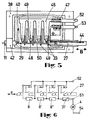
- FIGS. 4 and 5 show the switching device (6) of the ventilation device.
- the switching device (6) consists of a multi-stage step switch (7) and a plurality of power resistors (8). Step switches (7) and power resistors (8) form a structural unit which is flanged to an opening (32) in the air duct (1). Parts of the tap changer (7), in particular its switch contact connections (33) with good heat-conducting properties, and the power resistors (8) connected to them protrude into the air duct (1) and can be cooled by the air flow prevailing there.
- the power resistors (8) are made of a ceramic mass embedded, they form a resistor block (34) made up of several individual resistors (8, 8 ', 8'').
- a sleeve (35) holds the resistance block (34) on the tap changer (7).
- the housing (38) of the tap changer (7) consists of temperature-resistant plastic. Switch contacts (39) located in the housing (38) are arranged in pairs, they are held stationary in pairs.
- the switch contact pairs (39) lie outside the air duct (1); in an alternative embodiment of the invention, they could of course also be arranged inside the air duct (1).
- Crosspieces (40) separate the individual switching contact pairs (39) and form switching chambers (41).
- the driving end of the Bowden cable (11) is fastened to a receptacle (42) on the housing (38) of the tap changer (7).
- the adjusting wire (29) of the Bowden cable (11) which is exposed on this side is extended and is connected to movement by hanging it in with the actuator (27).
- the actuator (27) is guided in the housing (38) so that it can move in the stroke direction (B). The adjusting movements of the handle (9) follow between end positions.
- the actuator (27) is an insulating part with a slope (43) and a sliding surface (44). If the actuator (27) is guided past the switching contact pairs (39) by the adjusting wire (29) of the Bowden cable (11), these are opened or closed in rows depending on the stroke direction.
- the switch contacts (45, 46) of a switch contact pair (39) are closed in the absence of the actuator (27).
- One switch contact (46) is the opposite end of its switch contact connection (33).
- the second switch contact (45), which is electrically connected to a common connection (47), is extended beyond its contact zone (49) by a guide lug (48).
- the moving actuator (27) slides with its slope (43) along the line (50) under the guide lug (48) and lifts it onto its sliding surface (44), thereby separating the switch contacts (45, 46) concerned.
- switching contacts (45, 46) which are open even in the normal state and which make contact using an alternative actuator are conceivable.
- the tap changer (7) is closed dust-tight with a flap (51).
- the electrical external connections can be seen in FIG. 5, one conductor (52) leading to the vehicle electrical system (5) and the other conductor (53) leading to the blower motor (4).
- the equivalent circuit diagram in FIG. 6 shows the mode of operation of the ventilation device which can be switched in stages. Based on the indicated position '0' to '4' of the actuator (27), five switching positions of the tap changer are displayed. In position '0' the current path from connection (52) to connection (54) is interrupted, the blower motor (4) is shut down.
- a switch contact pair is closed in position '1'; the current path now leads from the connection (52) via the three power resistors with resistance values of, for example, 1.6 ohms (8), 0.8 ohms (8 ') and 0.4 ohms (8'') and via the thermal fuse (37 ) to the blower motor (4) and via the connection (54) back to the vehicle electrical system (5); the intermediate resistance of 2.8 ohms results in a low blower output in this switching stage. In positions '2' and '3' the intermediate resistance value decreases step by step and the blower output increases accordingly. In position '4' the current path runs directly from the connection (52) via the thermal fuse (37) to the blower motor (4); the blower develops its full performance due to the ineffective power resistors (8, 8 ', 8'').
Landscapes
- Physics & Mathematics (AREA)
- Thermal Sciences (AREA)
- Engineering & Computer Science (AREA)
- Mechanical Engineering (AREA)
- Air-Conditioning For Vehicles (AREA)
- Details Of Resistors (AREA)
Description
- Die Erfindung betrifft eine Belüftungsvorrichtung in einem Kraftfahrzeug mit mehrstufig einstellbarem Gebläse gemäß dem Oberbegriff des Anspruches 1.
- Solche Vorrichtungen sind in Kraftfahrzeugen regelmäßig vorzufinden und demnach wohlbekannt. Das "Kraftfahrtechnische Taschenbuch" der Firma R. Bosch, 20. Auflage, zeigt auf den Seiten 568 und 569 den Stromlaufplan eines Kraftfahrzeuges; im Abschnitt 7 des Stromlaufplanes ist das Gebläse der Belüftungsvorrichtung und seine Einstellbarkeit anhand von Vorwiderständen schematisch dargestellt. Durch das Einstellen verschiedener Gebläsestufen kann die Luftmenge der Belüftungsvorrichtung den Bedürfnissen im Fahrgastraum angepaßt werden.
- Die bekannten Belüftungsvorrichtungen verfügen jeweils über einen innerhalb des Armaturenbrettes befindlichen, elektrischen Stufenschalter. Der Stufenschalter ist aus praktischen Gründen unmittelbar verbunden mit einer innerhalb des Fahrgastraumes am Armaturenbrett zugänglichen Handhabe. Der Stellweg der Handhabe und der Schaltablauf bzw. die Kontaktanordnung des Stufenschalters verlaufen dabei gleichsinnig, z.B. längsgerichtet oder kreisförmig. Anhand des Stufenschalters ist der Elektromotor des Gebläses der Belüftungsvorrichtung mit dem Bordnetz des Kraftfahrzeuges verbindbar. Das vom Elektromotor angetriebene Gebläse erzeugt eine Luftströmung im Luftkanal der Vorrichtung. Die Luftströmung belüftet den Fahrgastraum. Das Gebläse ist über diverse Schaltstufen des Stufenschalters stufig stellbar. Dabei werden dem Elektromotor des Gebläses in den einzelnen Schaltstufen im Wert jeweils unterschiedliche Leistungswiderstände vorgeschaltet. Ein vorgeschalteter Leistungswiderstand mindert entsprechend seinem Wert die Antriebsleistung des Elektromotores und ist somit bestimmend für die erzeugte Luftströmung einer Gebläsestufe. Die Leistungswiderstände bestehen üblicherweise aus gewendetem Widerstandsdraht. Wegen ihrer starken, betriebsmäßigen Erhitzung sind die Leistungswiderstände entfernt vom Stufenschalter im Wirkbereich des Gebläses angeordnet, daß heißt, sie ragen in den Luftkanal und werden durch die Luftströmung im Luftkanal gekühlt. Die bekannten Leistungswiderstände bilden eine eigene, geschlossene Baugruppe, die zur Vermeidung von Funkenflug oftmals mit einer Keramikmasse vergossen ist. Die Leistungswiderstände sind durch ein mehradriges Kabel mit dem Stufenschalter und dem Elektromotor elektrisch verbunden.
- Bei einer Leistungsaufnahme des Elektromotors von 250 Watt fließen Ströme bis etwa 20 Ampere. Dementsprechend ist der Querschnitt eines Einzelleiters im mehradrigen Verbindungskabel mit 2,5 mm² gewählt. Die Temperatur am Schaltkontakt des Stufenschalters erhöht sich erfahrungsgemäß bei einem Strom von 20A um etwa 30C. Bei Sonneneinstrahlung kann sich der Innenraum eines Kraftfahrzeuges auf z.B. 70C aufheizen, schaltet man dann zu seiner Belüftung das Gebläse auf volle Leistung, so ergeben sich am Schaltkontakt des Stufenschalter, also im Bereich des Armaturenbrettes, bereits Temperaturen um 100C.
- Dieser Umstand und die hohe betriebsmäßige Eigenerwärmung der Leistungswiderstände führten zu der bekannten und regelmäßig angewendeten Gliederung einer stufig stellbaren Belüftungsvorrichtung in eine erste Baugruppe einer Schalteinrichtung, mit einem oftmals rastmarkierten Stufenschalter im Armaturenbrett, in eine zweite Baugruppe der Schalteinrichtung mit regelmäßig mehreren Leistungswiderständen im Innenbereich eines Luftkanals, in ein Verbindungsteil, bestehend aus einem mehradrigen Kabel mit hohem Leiterquerschnitt, das die erste Baugruppe mit der zweiten Baugruppe elektrisch verbindet und in eine ebenfalls mit dem Stufenschalter elektrisch verbundene dritte Baugruppe mit einem elektromotorisch angetriebenen Gebläse.
- Es sind daneben auch elektronisch steuerbare Belüftungsvorrichtungen bekannt. In der EP-A-0 143 176 ist eine derartige Belüftungsvorrichtung beschrieben, wobei solche Bauteile der elektronischen Steuerungseinrichtung, die eine hohe Verlustleistung aufweisen, auf einer Klappe innerhalb eines Luftkanals angebracht sind. Derartige, meist stufenlos einstellbare Vorrichtungen sind von der Erfindung nicht betroffen.
- Neuerdings werden vom Gebläse einer Belüftungsvorrichtung höhere Leistungen abverlangt. Insbesondere dann, wenn im Luftkanal der Vorrichtung ein oder mehrere Filter eingebracht sind, die sich mit fortschreitender Lebensdauer zusetzen können und dadurch ihren Luftwiderstand erhöhend die Belüftung des Fahrgastraumes behindern. Eine solche Behinderung ist durch größere Gebläseleistung zumindest teilweise kompensierbar. Hat man bislang Gebläsemotoren mit einer Leistungsaufnahme von z.B. 250 Watt verwendet, kommen neuerdings Gebläsemotoren mit einer Leistungsaufnahme bis etwa 500 Watt zum Einsatz. Dies mag sich künftig noch weiter steigern. Dabei erhöht sich der maximale Betriebsstrom, z.B. auf 40 Ampere und mehr. Als Folge des höheren Stromes ist der Leiterquerschnitt des mehradrigen Verbindungskabels der Schalteinrichtung auf 4 mm² zu vergrößern. Ein solches Kabel ist erheblich teurer und weniger handlich. Eine andere Folge des höheren Stromes ist eine weitergehende Kontakterwärmung im Stufenschalter, was die eigene Lebensdauer und die benachbart angeordneter, insbesondere elektronischer Bauelemente beeinträchtigt. Letzteres wäre beispielsweise anhand eines Stufenschalters mit geringerem Kontaktwiderstand zu bewältigen, jedoch fehlt einem solchen Leistungsschalter oftmals die gewünschte leichtgängige Stellbarkeit und die Lebensdauer. Den geschilderten, durch die Leistungserhöhung ausgelösten Unwägbarkeiten und Teuerungen bei einer Belüftungsvorrichtung der eingangs bezeichneten Art durch ein in anderer Weise verbessertes Konzept entgegenzuwirken ist Aufgabe der Erfindung.
- Als Lösung der Aufgabe ist vorgeschlagen, daß sich der Stufenschalter ebenfalls, gleich den Leistungswiderständen, im Wirkbereich des Gebläses befindet, wobei er eine bauliche Einheit mit den Leistungswiderständen ausbildet, und wobei der Stufenschalter mittels eines Bowdenzuges von einer Handhabe im Fahrgastraum aus betätigbar ist. Dies besagt insbesondere, daß der Stufenschalter zumindest partiell von der Luftströmung beaufschlagt ist. Überwärme, z.B. durch den Nennstrom erzeugte Kontakterwärmung, ist dann gut anhand der Luftströmung ableitbar. Der Nennstrom fließt bei maximaler Gebläseleistung. Wegen der einrichtbaren, räumlichen Nähe des Stufenschalters zu den Leistungswiderständen genügt ein entsprechend verkürztes Verbindungskabel; bei einer baulichen Vereinigung von Stufenschalter und Leistungswiderständen entfällt es sogar. Dies ist ein weiterer Vorteil der vorgeschlagenen Belüftungsvorrichtung gegenüber den bekannten Vorrichtungen.
- Die mit der Erfindung geschaffene räumliche Trennung von Stufenschalter und Handhabe läßt Beeinträchtigungen des Einstellvorganges vermuten. Es sind insbesondere auch Weg-Toleranzen zu befürchten, die eine Übereinstimmung zwischen einer optischen oder fühlbaren Markierung der Handhabe und einer zugeordneten Schaltposition im Stufenschalter gefährden können. Solche von der Erfindung eher ablenkende Sachverhalte sind durch besondere Aufmerksamkeit bei der Auswahl geeigneter Stellmittel und bei der Konzeption eines geeigneten Stufenschalters zu beachten. Gut nutzbar sind z.B. Stellmittel, die keine schematische Zuordnung oder Ausrichtung erfordern. Dadurch erlangt man Freiheiten beim Plazieren einer Handhabe einerseits und des Stufenschalters andererseits. Ein Bowdenzug ist beispielsweise ein solches Stellmittel. Vorteilhaft sind auch Stellmittel oder Stelleinrichtungen, die eine Stellbewegung umformen, z.B. eine Drehbewegung in eine Längsbewegung. Ebenso vorteilhaft sind Stellmittel, die in der Lage sind, Stellwege zu kürzen oder zu verlängern, z.B. Stellhebel, Stellgetriebe. Derartige Stellmittel vermögen designbestimmte Stellwege einer Handhabe den Erfordernissen des Stufenschalters anzupassen. Mit solchen Stellmitteln ergeben sich aber auch Freiheiten z.B. bei der Bemessung der Schaltwege im Stufenschalter, was hilfreich ist, um Bau- oder Weg-Toleranzen zu beherrschen. Dabei wird man einen entsprechenden Stufenschalter so konzipieren, daß die größtmögliche Weg-Toleranz über die Länge des Schalthubes zu bewältigen ist. Vorzugsweise wählt man ein von den Stellmitteln stellbares Isolierteil als Schaltglied des Stufenschalters, das sich mit entsprechendem Stellhub an einem stationär gehaltenen Schaltkontaktpaar positioniert und dieses je nach Bauart öffnet oder schließt. Kontakttoleranz entfällt bei einer solchen Anordnung.
- Nachstehend wird ein vorteilhaftes Ausführungsbeispiel der Erfindung anhand von Zeichnungen beschrieben. Die Zeichnungen zeigen in
- Figur 1
- eine erfindungsgemäße Belüftungsvorrichtung, schematisch dargestellt im Umriß eines Kraftfahrzeuges,
- Figur 2
- eine Handhabe und deren Stellbewegung übertragende Stellmittel in einer Vorrichtung gemäß Figur 1 im Schnitt,
- Figur 3
- die Stellmittel gemäß Figur 2, längs der Linie III-III,
- Figur 4
- einen von den Stellmitteln gemäß Figur 2 angetriebenen Stufenschalter,
- Figur 5
- den Stufenschalter aus Figur 4 in Seitenansicht längs der Linie V-V,
- Figur 6
- ein Ersatzschaltbild des Stufenschalters.
- In Figur 1 ist eine erfindungsgemäße Belüftungsvorrichtung schematisch dargestellt. Dabei ist innerhalb der Kontur eines PKW-Vorderteiles ein Luftkanal (1) erkennbar. Durch den Luftkanal (1) wird im Motorraum des Fahrzeuges erwärmte oder von außen einströmende Luft zum Fahrgastraum (2) geführt und dort verteilt. Die Luftströmung im Luftkanal (1) wird insbesondere bei stehendem Fahrzeug von einem Gebläse (3) unterstützt.
- Das Gebläse (3) wird durch einen Gebläsemotor (4) angetrieben. Gebläse (3) und Gebläsemotor (4) bilden regelmäßig eine Baueinheit. Der Gebläsemotor (4) wird aus dem Bordnetz (5) des Fahrzeuges elektrisch versorgt; er ist mittels einer Schalteinrichtung (6) vom Bordnetz (5) trennbar und damit abschaltbar. Die Schalteinrichtung (6) ist am Luftkanal (1) befestigt; sie ragt teilweise in den Luftkanal (1) und wird dort von der Luftströmung im Luftkanal (1) gekühlt. Die Luftströmung wird von dem Gebläse (3) erzeugt. Somit befindet sich die Schalteinrichtung (6) im Wirkbereich des Gebläses (3). Die Schalteinrichtung (6) besteht aus einem mehrstufigen Stufenschalter (7) und einer Gruppe von Leistungswiderständen (8). Im Fahrgastraum (2) befindet sich eine Handhabe (9) zum Einstellen des Stufenschalters (7). Stellbewegungen der Handhabe (9) werden anhand von Stellmitteln (10, 11) auf den Stufenschalter übertragen. Die Stellbewegungen der Handhabe (9) werden dabei von den Stellmitteln (10) umgeformt und übersetzt und so den Erfordernissen des Stufenschalters angepaßt. Die Stellbewegung überträgt ein Bowdenzug (11). Der Stufenschalter (7) hat mehrere Schaltstufen für unterschiedliche Gebläseleistungen.
- Teile der Stellmittel (10), vornehmlich solche zur Anpassung von Stellbewegungen, und die Handhabe (9) sind am Armaturenbrett (12) des Fahrzeuges angebracht. Dort ist gemäß Figur 2 zwischen Seitenwänden (13, 14) eine Stellwelle (15) gelagert. Die Seitenwände (13, 14) sind anhand von Zwischenstücken (16) auf Abstand gehalten. Die Seitenwände (13, 14) weisen Lager (17, 18) aus, in denen die Stellwelle (15) lagert. Die Stellwelle (15) durchragt die eine Seitenwand (14). Das sich dabei ausbildende, freie Wellenende (19) trägt die im Fahrgastraum (2) betätigbare Handhabe (9). Auf der Außenfläche des einen Lagers (17) ist ein Zahnritzel (20) drehgelagert, das wiederum eine in der Seitenwand (13) geführte Zahnstange (21) antreibt. Die Zahnstange an die gemäß Figur 3 ein Bowdenzug (11) angreift, ist durch ein Rastrad (23) beschwert. Dem Zahnritzel (20) ist ein Treibarm (24) angeformt. Die Stellwelle (15) ist mit einem V-förmigen gestalteten Stellarm (25) ausgestattet. Der Treibarm (24) greift in die V-Form des Stellarmes (25) und wird von diesem drehgestellt. Stellarm (25) und Treibarm (24) sind bis zur gegenseitigen Anlage durch ein Federteil (26) elastisch verbunden. Das Federteil (26) unterstützt die Wirkung des Rastrades (23). Anhand der Stellmittel (10) wird eine Stellbewegung der Handhabe (9) auf die Zahnstange (21) übertragen, wobei gemäß Figur 3 eine Drehung des Zahnritzels (Pfeil A) in einen Hub (Pfeil B) der Zahnstange (21) bzw. des Bowdenzuges (11) gewandelt wird. Der Bowdenzug (11) überträgt den Hub (B) als Teil der Stellmittel (10) auf ein Stellglied (27, Figur 4) des Stufenschalters (7). Der Bowdenzug (11) ist antriebsseitig an einer Aufnahme (28) verankert. Das freigelegte Ende seines Stelldrahtes (29) ist durch Einhaken (22) mit der Zahnstange (21) bewegungsverbunden. Die Zahnstange (21) ist mit Rastnocken (30) versehen. Das mittels einem Federteil (31) vorgespannte Rastrad (23) wirkt mit den Rastnocken (30) im Sinn einer an der Handhabe (9) erkennbaren Rastung zusammen. Die Raststufen (C) entsprechen den Schaltstufen im Stufenschalter (7).
- In den Figuren 4 und 5 ist die Schalteinrichtung (6) der Belüftungsvorrichtung dargestellt. Die Schalteinrichtung (6) besteht aus einem mehrstufigen Stufenschalter (7) und aus einer Mehrzahl von Leistungswiderständen (8). Stufenschalter (7) und Leistungswiderstände (8) bilden eine bauliche Einheit, die an eine Öffnung (32) des Luftkanals (1) angeflanscht ist. Dabei ragen Teile des Stufenschalters (7), insbesondere seine gut wärmeleitend ausgebildeten Schaltkontaktanschlüsse (33), und die daran angeschlossenen Leistungswiderstände (8) in den Luftkanal (1) hinein und sind durch den dort vorherrschenden Luftstrom kühlbar. Die Leistungswiderstände (8) sind durch eine Keramikmasse eingebettet, sie bilden einen Widerstandsblock (34) aus mehreren Einzelwiderständen (8, 8', 8''). Eine Manschette (35) hält den Widerstandsblock (34) am Stufenschalter (7). Die Anschlüsse (36) der einzelnen Leistungswiderstände (8) ragen aus dem Widerstandsblock (34), sie (36) sind jeweils zu einem Schaltkontaktanschluß (33) des Stufenschalters (7) geführt und mit diesem durch Krampen elektrisch verbunden. Eine Thermosicherung (37) schützt die Schalteinrichtung (6) vor Überhitzung, sie unterbricht erforderlichenfalls den Stromfluß zum Gebläsemotor (4). Das Gehäuse (38) des Stufenschalters (7) besteht aus temperaturbeständigem Kunststoff. Im Gehäuse (38) befindliche Schaltkontakte (39) sind paarweise angeordnet, sie sind paarweise stationär gehalten. Im Ausführungsbeispiel liegen die Schaltkontaktpaare (39) außerhalb des Luftkanals (1), sie könnten in einer alternativen Ausgestaltung der Erfindung selbstverständlich auch innerhalb des Luftkanals (1) angeordnet sein. Stege (40) trennen die einzelnen Schaltkontaktpaare (39) und bilden Schaltkammern (41). Das treibende Ende des Bowdenzuges (11) ist an einer Aufnahme (42) am Gehäuse (38) des Stufenschalters (7) befestigt. Der diesseits freigelegte Stelldraht (29) des Bowdenzuges (11) ist verlängert und durch Einhängen mit dem Stellglied (27) bewegungsverbunden. Das Stellglied (27) ist im Gehäuse (38) in Hubrichtung (B) beweglich geführt, es folgt zwischen Endstellungen den Stellbewegungen der Handhabe (9). Das Stellglied (27) ist ein Isolierteil mit einer Schräge (43) und einer Gleitfläche (44). Wird das Stellglied (27) vom Stelldraht (29) des Bowdenzuges (11) an den Schaltkontaktpaaren (39) vorbeigeführt, dann werden diese je nach Hubrichtung reihenweise geöffnet oder geschlossen.
- Im Ausführungsbeispiel sind die Schaltkontakte (45, 46) eines Schaltkontaktpaares (39) bei Abwesenheit des Stellgliedes (27) geschlossen. Der eine Schaltkontakt (46) ist das entgegengesetzte Ende seines Schaltkontaktanschlusses (33). Der zweite Schaltkontakt (45), der elektrisch mit einem Sammelanschluß (47) verbunden ist, ist durch eine Führungsnase (48) über seine Kontaktzone (49) hinaus verlängert. Das bewegte Stellglied (27) gleitet mit seiner Schräge (43) längs der Linie (50) unter die Führungsnase (48) und liftet diese auf seine Gleitfläche (44), dabei die betroffenen Schaltkontakte (45, 46) trennend. - Es sind in einer weiteren Ausgestaltung der Erfindung auch im Normalzustand offene Schaltkontakte (45, 46) denkbar, die anhand eines alternativen Stellgliedes kontaktieren. - Der Stufenschalter (7) ist mit einer Klappe (51) staubdicht verschlossen. In Figur 5 sind die elektrischen Außenanschlüsse erkennbar, wobei der eine Leiter (52) zum Bordnetz (5) führt und der andere Leiter (53) zum Gebläsemotor (4).
- Das Ersatzschaltbild in Figur 6 läßt die Arbeitsweise der stufig schaltbaren Belüftungsvorrichtung erkennen. Anhand der angedeuteten Position '0' bis '4' des Stellgiedes (27) sind fünf Schaltpositionen des Stufenschalters angezeigt. In Position '0' ist der Strompfad vom Anschluß (52) zum Anschluß (54) unterbrochen, der Gebläsemotor (4) ist stillgelegt. In Position '1' ist ein Schaltkontaktpaar geschlossen; der Strompfad führt nunmehr vom Anschluß (52) kommend über die drei Leistungswiderstände mit Widerstandswerten von beispielsweise 1,6 Ohm (8), 0,8 Ohm (8') und 0,4 Ohm (8'') und über die Thermosicherung (37) zum Gebläsemotor (4) und über den Anschluß (54) zurück zum Bordnetz (5); der zwischengeschaltete Widerstand von insgesamt 2,8 Ohm bewirkt in dieser Schaltstufe eine geringe Gebläseleistung. In den Positionen '2' und '3' verringert sich der zwischengeschaltete Widerstandswert stufenweise und die Gebläseleistung erhöht sich entsprechend. In Position '4' verläuft der Strompfad unmittelbar vom Anschluß (52) über die Thermosicherung (37) zum Gebläsemotor (4); das Gebläse entfaltet infolge der unwirksamen Leistungswiderstände (8, 8', 8'') seine volle Leistung.
-
- 1
- Luftkanal
- 2
- Fahrgastraum
- 3
- Gebläse
- 4
- Gebläsemotor
- 5
- Bordnetz
- 6
- Schalteinrichtung
- 7
- Stufenschalter
- 8, 8', 8''
- Leistungswiderstand
- 9
- Handhabe
- 10
- Stellmittel
- 11
- Bowdenzug
- 12
- Armaturenbrett
- 13
- Seitenwand
- 14
- Seitenwand
- 15
- Stellwelle
- 16
- Zwischenstück
- 17
- Lager
- 18
- Lager
- 19
- Wellenende
- 20
- Zahnritzel
- 21
- Zahnstange
- 22
- Haken
- 23
- Rastrad
- 24
- Treibarm
- 25
- Stellarm
- 26
- Federteil
- 27
- Stellglied
- 28
- Aufnahme
- 29
- Stelldraht
- 30
- Rastnocke
- 31
- Federteil
- 32
- Öffnung
- 33
- Schaltkontaktanschluß
- 34
- Widerstandsblock
- 35
- Manschette
- 36
- Anschluß
- 37
- Thermosicherung
- 38
- Gehäuse
- 39
- Schaltkontaktpaar
- 40
- Steg
- 41
- Schaltkammer
- 42
- Aufnahme
- 43
- Schräge
- 44
- Gleitfläche
- 45
- Schaltkontakt
- 46
- Schaltkontakt
- 47
- Sammelanschluß
- 48
- Führungsnase
- 49
- Kontaktzone
- 50
- Linie
- 51
- Klappe
- 52
- Anschluß (-Leiter)
- 53
- Anschluß (-Leiter)
- 54
- Anschluß
- A
- Drehsinn
- B
- Hubrichtung
- C
- Raststufe
Claims (6)
- Belüftungsvorrichtung eines Kraftfahrzeuges, insbesondere zur Belüftung des Fahrgastraumes (2), mit einem Luftkanal (1), in dem sich ein durch einen Elektromotor (4) angetriebenes, mehrstufig einstellbares Gebläse (3) befindet und mit einer elektromechanischen Schalteinrichtung (6) für das mehrstufige Einstellen des Gebläses (3), wobei im Wirkbereich des Gebläses (3) befindliche Leistungswiderstände (8, 8', 8'') dem Elektromotor (4) anhand eines vom Fahrgastraum (2) aus mechanisch betätigbaren Stufenschalters (7) stufig vorschaltbar sind,
dadurch gekennzeichnet,
daß sich der Stufenschalter (7) ebenfalls im Wirkbereich des Gebläses (3) befindet, wobei er eine bauliche Einheit mit den Leistungswiderständen (8, 8', 8'') ausbildet, und wobei der Stufenschalter (7) mittels eines Bowdenzuges (11) von einer Handhabe (9) im Fahrgastraum (2) aus betätigbar ist. - Belüftungsvorrichtung nach Anspruch 1,
dadurch gekennzeichnet,
daß sie Einrichtungen (20, 21) aufweist, die bewirken, daß eine Stellbewegung der Handhabe (9) umgeformt und/oder übersetzt bzw. untersetzt wird. - Belüftungsvorrichtung nach Anspruch 1 oder 2,
dadurch gekennzeichnet,
daß die bauliche Einheit aus Leistungswiderständen (8, 8', 8'') und dem Stufenschalter (7) an eine Öffnung (32) des Luftkanals (1) angeflanscht ist und zumindest teilweise in diesen hineinragt. - Belüftungsvorrichtung nach einem der Ansprüche 1 bis 3,
dadurch gekennzeichnet,
daß die Leistungswiderstände (8, 8', 8'') innerhalb des Luftkanals (1) und der Stufenschalter (7) außerhalb diesem angeordnet sind. - Belüftungsvorrichtung nach einem der Ansprüche 1 bis 4,
dadurch gekennzeichnet,
daß die innerhalb des Luftkanals (1) befindlichen Leistungswiderstände (8, 8', 8'') durch Ankrampen unmittelbar elektrisch verbunden sind mit ebenfalls innerhalb des Luftkanals (1) befindlichen, gut wärmeleitend ausgebildeten Schaltkontaktanschlüssen (33) des Stufenschalters (7). - Belüftungsvorrichtung nach einem der Ansprüche 1 bis 5,
dadurch gekennzeichnet,
daß der Stufenschalter (7) mit stationär gehaltenen Schaltkontaktpaaren (39) ausgestattet ist und ein von den Stellmitteln (10) getriebenes Isolierteil (27) die Schaltkontaktpaare (39) nacheinander öffnet oder schließt.
Priority Applications (6)
| Application Number | Priority Date | Filing Date | Title |
|---|---|---|---|
| EP92103813A EP0558785B1 (de) | 1992-03-06 | 1992-03-06 | Belüftungsvorrichtung |
| DE59205250T DE59205250D1 (de) | 1992-03-06 | 1992-03-06 | Belüftungsvorrichtung |
| ES92103813T ES2082248T3 (es) | 1992-03-06 | 1992-03-06 | Dispositivo de ventilacion. |
| DE9204214U DE9204214U1 (de) | 1992-03-06 | 1992-03-28 | Belüftungsvorrichtung |
| US08/026,297 US5322471A (en) | 1992-03-06 | 1993-03-04 | Ventilation apparatus |
| JP5045497A JPH0687320A (ja) | 1992-03-06 | 1993-03-05 | 換気装置 |
Applications Claiming Priority (1)
| Application Number | Priority Date | Filing Date | Title |
|---|---|---|---|
| EP92103813A EP0558785B1 (de) | 1992-03-06 | 1992-03-06 | Belüftungsvorrichtung |
Publications (2)
| Publication Number | Publication Date |
|---|---|
| EP0558785A1 EP0558785A1 (de) | 1993-09-08 |
| EP0558785B1 true EP0558785B1 (de) | 1996-01-31 |
Family
ID=8209404
Family Applications (1)
| Application Number | Title | Priority Date | Filing Date |
|---|---|---|---|
| EP92103813A Expired - Lifetime EP0558785B1 (de) | 1992-03-06 | 1992-03-06 | Belüftungsvorrichtung |
Country Status (5)
| Country | Link |
|---|---|
| US (1) | US5322471A (de) |
| EP (1) | EP0558785B1 (de) |
| JP (1) | JPH0687320A (de) |
| DE (2) | DE59205250D1 (de) |
| ES (1) | ES2082248T3 (de) |
Families Citing this family (10)
| Publication number | Priority date | Publication date | Assignee | Title |
|---|---|---|---|---|
| US5481885A (en) * | 1994-07-22 | 1996-01-09 | Ford Motor Company | Ventilation system for an automotive vehicle instrument panel |
| DE4430484A1 (de) * | 1994-08-27 | 1996-02-29 | Behr Gmbh & Co | Bedienschalter für eine Heizungs- und Klimaanlage eines Kraftfahrzeugs |
| US5669813A (en) * | 1996-05-03 | 1997-09-23 | Ford Motor Company | Apparatus for storing and cooling electronic devices and/or modules in a vehicle |
| DE19847919A1 (de) * | 1998-10-19 | 2000-04-20 | Valeo Klimasysteme Gmbh | Widerstandsmodul mit integriertem Stellelement |
| DE19918907B4 (de) * | 1999-04-26 | 2008-12-24 | Valeo Klimasysteme Gmbh | Schaltvorrichtung |
| US6789654B2 (en) | 2003-01-22 | 2004-09-14 | Caterpillar Inc | Multiple coupling fan drive |
| US7240660B1 (en) | 2006-09-21 | 2007-07-10 | Ford Global Technologies, Llc | Heat management for control unit |
| US8206204B2 (en) * | 2006-09-21 | 2012-06-26 | Ford Global Technologies, Llc | Control unit heat management |
| DE102009053548A1 (de) * | 2009-11-18 | 2011-05-19 | Behr Gmbh & Co. Kg | Kühlerzargensystem |
| FR3103576B1 (fr) * | 2019-11-26 | 2023-12-29 | Psa Automobiles Sa | Procédé et dispositif de contrôle d’un dispositif de communication de véhicule |
Family Cites Families (9)
| Publication number | Priority date | Publication date | Assignee | Title |
|---|---|---|---|---|
| US2824939A (en) * | 1955-03-17 | 1958-02-25 | Westinghouse Electric Corp | Cooling means for metal-clad switchgear |
| US3088013A (en) * | 1956-04-02 | 1963-04-30 | James P Watson | Contact cooling means |
| US3213232A (en) * | 1963-05-09 | 1965-10-19 | Ite Circuit Breaker Ltd | Forced air-cooled thermally calibrated circuit breaker |
| DE7138451U (de) * | 1971-10-11 | 1972-02-10 | Kreis P | Vorrichtung zum stufenlosen Regeln der Rotationsgeschwindigkeit von Geblasen an Wohnwagenheizungen |
| FR2360934A2 (fr) * | 1976-05-21 | 1978-03-03 | Torrix Sa Ets | Variateur de tension |
| JPS5835396B2 (ja) * | 1978-11-20 | 1983-08-02 | 株式会社日立製作所 | 電動送風機の制御回路 |
| DE3331890A1 (de) * | 1983-09-03 | 1985-03-28 | Süddeutsche Kühlerfabrik Julius Fr. Behr GmbH & Co KG, 7000 Stuttgart | Kraftfahrzeug-heizungs- und/oder klimaanlage |
| DE3332984A1 (de) * | 1983-09-13 | 1985-03-28 | Aurora Konrad G. Schulz Gmbh & Co, 6933 Mudau | Anordnung von stellorganen, insbesondere fuer vorrichtungen zur beheizung und belueftung von fahrerkabinen, fahrgastraeumen od.dgl. in nutzfahrzeugen |
| EP0363191B1 (de) * | 1988-10-07 | 1999-01-27 | Fujikura Ltd. | Flacher Widerstand für Gebläsekontrolleinheit einer Automobil-Klimaanlage und Gebläsekontrolleinheit |
-
1992
- 1992-03-06 EP EP92103813A patent/EP0558785B1/de not_active Expired - Lifetime
- 1992-03-06 DE DE59205250T patent/DE59205250D1/de not_active Expired - Fee Related
- 1992-03-06 ES ES92103813T patent/ES2082248T3/es not_active Expired - Lifetime
- 1992-03-28 DE DE9204214U patent/DE9204214U1/de not_active Expired - Lifetime
-
1993
- 1993-03-04 US US08/026,297 patent/US5322471A/en not_active Expired - Fee Related
- 1993-03-05 JP JP5045497A patent/JPH0687320A/ja not_active Withdrawn
Also Published As
| Publication number | Publication date |
|---|---|
| JPH0687320A (ja) | 1994-03-29 |
| EP0558785A1 (de) | 1993-09-08 |
| ES2082248T3 (es) | 1996-03-16 |
| DE9204214U1 (de) | 1992-06-11 |
| US5322471A (en) | 1994-06-21 |
| DE59205250D1 (de) | 1996-03-14 |
Similar Documents
| Publication | Publication Date | Title |
|---|---|---|
| EP1157867B1 (de) | Elektrische Heizvorrichtung, insbesondere für den Einsatz in Kraftfahrzeugen | |
| EP1492384B1 (de) | Elektrische Heizeinrichtung, insbesondere für ein Kraftfahrzeug | |
| EP1873800B1 (de) | Elektrische Werkzeugmaschine und Schalter hierfür | |
| EP0712145A1 (de) | Antriebseinrichtung mit einem Antriebselement aus einer Formgedächtnislegierung | |
| EP0558785A1 (de) | Belüftungsvorrichtung | |
| DE69129424T2 (de) | Geschwindigkeitskommutationsvorrichtung für einen elektrischen Motor | |
| DE102013108653A1 (de) | Steuereinheit | |
| DE3039727C2 (de) | Steuerung für die Klimaanlage eines Kraftfahrzeuges | |
| DE2417890B2 (de) | Zahnaerztliche einrichtung | |
| DE4217037C1 (de) | Steuerungseinrichtung für einen elektrischen Antrieb einer Kraftfahrzeug-Heizungs-oder Klimaanlage | |
| DE69306977T2 (de) | Mechanische Vorrichtung mit veränderlicher resistiver Schaltung zur Steuerung einer Last, insbesondere eines Elektromotors | |
| EP0980084B1 (de) | Elektrische Schalterkombination | |
| DE3239642C2 (de) | ||
| DE69508213T2 (de) | Zentralisierter Verbindungsblock für eine Heizungs- und/oder Klimaanlage eines Kraftfahrzeuges | |
| DE2843967C3 (de) | Vorschaltwiderstand-Bauteil, insbesondere für Heizungsgebläse für Kraftfahrzeuge | |
| DE3719639C2 (de) | ||
| DE2403316C3 (de) | Steuervorrichtung für Klimaanlagen in Fahrzeugen, insbesondere Kraftfahrzeugen | |
| DE2831537A1 (de) | Linear-betaetigungseinrichtung | |
| EP2162979A2 (de) | Ansteuereinrichtung für einen elektromotor | |
| DE2853746C2 (de) | Sicherheitsparklichtschaltung in einem Lenkstockschalter für Kraftfahrzeuge und Schalter dazu | |
| DE69717392T2 (de) | Multifunktional-Verbindungsvorrichtung für Armaturenbrett, insbesondere in einem Kraftfahrzeug | |
| DE102006015502B4 (de) | Gestufte Drehzahlverstellung für einen Niederspannungselektromotor | |
| EP0884204A1 (de) | Betätingungsvorrichtung | |
| EP0726179A1 (de) | Bediengerät für eine Heizungs- und/oder Klimaanlage | |
| DE8412947U1 (de) | Elektrisches Aggregat |
Legal Events
| Date | Code | Title | Description |
|---|---|---|---|
| PUAI | Public reference made under article 153(3) epc to a published international application that has entered the european phase |
Free format text: ORIGINAL CODE: 0009012 |
|
| AK | Designated contracting states |
Kind code of ref document: A1 Designated state(s): DE ES FR GB IT PT SE |
|
| 17P | Request for examination filed |
Effective date: 19930720 |
|
| 17Q | First examination report despatched |
Effective date: 19950227 |
|
| GRAA | (expected) grant |
Free format text: ORIGINAL CODE: 0009210 |
|
| AK | Designated contracting states |
Kind code of ref document: B1 Designated state(s): DE ES FR GB IT PT SE |
|
| ET | Fr: translation filed | ||
| GBT | Gb: translation of ep patent filed (gb section 77(6)(a)/1977) |
Effective date: 19960208 |
|
| REF | Corresponds to: |
Ref document number: 59205250 Country of ref document: DE Date of ref document: 19960314 |
|
| REG | Reference to a national code |
Ref country code: ES Ref legal event code: FG2A Ref document number: 2082248 Country of ref document: ES Kind code of ref document: T3 |
|
| ITF | It: translation for a ep patent filed | ||
| SC4A | Pt: translation is available |
Free format text: 960221 AVAILABILITY OF NATIONAL TRANSLATION |
|
| PLBE | No opposition filed within time limit |
Free format text: ORIGINAL CODE: 0009261 |
|
| STAA | Information on the status of an ep patent application or granted ep patent |
Free format text: STATUS: NO OPPOSITION FILED WITHIN TIME LIMIT |
|
| 26N | No opposition filed | ||
| PGFP | Annual fee paid to national office [announced via postgrant information from national office to epo] |
Ref country code: GB Payment date: 19970213 Year of fee payment: 6 |
|
| PGFP | Annual fee paid to national office [announced via postgrant information from national office to epo] |
Ref country code: FR Payment date: 19970214 Year of fee payment: 6 |
|
| PGFP | Annual fee paid to national office [announced via postgrant information from national office to epo] |
Ref country code: SE Payment date: 19970221 Year of fee payment: 6 |
|
| PGFP | Annual fee paid to national office [announced via postgrant information from national office to epo] |
Ref country code: PT Payment date: 19970226 Year of fee payment: 6 |
|
| PGFP | Annual fee paid to national office [announced via postgrant information from national office to epo] |
Ref country code: ES Payment date: 19970321 Year of fee payment: 6 |
|
| PG25 | Lapsed in a contracting state [announced via postgrant information from national office to epo] |
Ref country code: GB Free format text: LAPSE BECAUSE OF NON-PAYMENT OF DUE FEES Effective date: 19980306 |
|
| PG25 | Lapsed in a contracting state [announced via postgrant information from national office to epo] |
Ref country code: SE Free format text: LAPSE BECAUSE OF NON-PAYMENT OF DUE FEES Effective date: 19980307 Ref country code: ES Free format text: LAPSE BECAUSE OF NON-PAYMENT OF DUE FEES Effective date: 19980307 |
|
| PG25 | Lapsed in a contracting state [announced via postgrant information from national office to epo] |
Ref country code: FR Free format text: THE PATENT HAS BEEN ANNULLED BY A DECISION OF A NATIONAL AUTHORITY Effective date: 19980331 |
|
| PG25 | Lapsed in a contracting state [announced via postgrant information from national office to epo] |
Ref country code: PT Free format text: LAPSE BECAUSE OF NON-PAYMENT OF DUE FEES Effective date: 19980930 |
|
| GBPC | Gb: european patent ceased through non-payment of renewal fee |
Effective date: 19980306 |
|
| EUG | Se: european patent has lapsed |
Ref document number: 92103813.9 |
|
| REG | Reference to a national code |
Ref country code: FR Ref legal event code: ST |
|
| REG | Reference to a national code |
Ref country code: PT Ref legal event code: MM4A Free format text: LAPSE DUE TO NON-PAYMENT OF FEES Effective date: 19980930 |
|
| PGFP | Annual fee paid to national office [announced via postgrant information from national office to epo] |
Ref country code: DE Payment date: 20000224 Year of fee payment: 9 |
|
| REG | Reference to a national code |
Ref country code: ES Ref legal event code: FD2A Effective date: 20000503 |
|
| PG25 | Lapsed in a contracting state [announced via postgrant information from national office to epo] |
Ref country code: DE Free format text: LAPSE BECAUSE OF NON-PAYMENT OF DUE FEES Effective date: 20020101 |
|
| PG25 | Lapsed in a contracting state [announced via postgrant information from national office to epo] |
Ref country code: IT Free format text: LAPSE BECAUSE OF NON-PAYMENT OF DUE FEES Effective date: 20050306 |