EP0557716A1 - Supporting device for railway rails - Google Patents
Supporting device for railway rails Download PDFInfo
- Publication number
- EP0557716A1 EP0557716A1 EP93100851A EP93100851A EP0557716A1 EP 0557716 A1 EP0557716 A1 EP 0557716A1 EP 93100851 A EP93100851 A EP 93100851A EP 93100851 A EP93100851 A EP 93100851A EP 0557716 A1 EP0557716 A1 EP 0557716A1
- Authority
- EP
- European Patent Office
- Prior art keywords
- bearing plate
- rail
- bearing
- elastic elements
- track system
- Prior art date
- Legal status (The legal status is an assumption and is not a legal conclusion. Google has not performed a legal analysis and makes no representation as to the accuracy of the status listed.)
- Granted
Links
Images

Classifications
-
- E—FIXED CONSTRUCTIONS
- E01—CONSTRUCTION OF ROADS, RAILWAYS, OR BRIDGES
- E01B—PERMANENT WAY; PERMANENT-WAY TOOLS; MACHINES FOR MAKING RAILWAYS OF ALL KINDS
- E01B9/00—Fastening rails on sleepers, or the like
- E01B9/62—Rail fastenings incorporating resilient supports
-
- E—FIXED CONSTRUCTIONS
- E01—CONSTRUCTION OF ROADS, RAILWAYS, OR BRIDGES
- E01B—PERMANENT WAY; PERMANENT-WAY TOOLS; MACHINES FOR MAKING RAILWAYS OF ALL KINDS
- E01B2/00—General structure of permanent way
- E01B2/003—Arrangement of tracks on bridges or in tunnels
-
- E—FIXED CONSTRUCTIONS
- E01—CONSTRUCTION OF ROADS, RAILWAYS, OR BRIDGES
- E01B—PERMANENT WAY; PERMANENT-WAY TOOLS; MACHINES FOR MAKING RAILWAYS OF ALL KINDS
- E01B2204/00—Characteristics of the track and its foundations
- E01B2204/01—Elastic layers other than rail-pads, e.g. sleeper-shoes, bituconcrete
-
- E—FIXED CONSTRUCTIONS
- E01—CONSTRUCTION OF ROADS, RAILWAYS, OR BRIDGES
- E01B—PERMANENT WAY; PERMANENT-WAY TOOLS; MACHINES FOR MAKING RAILWAYS OF ALL KINDS
- E01B2204/00—Characteristics of the track and its foundations
- E01B2204/12—Floating rails or sleepers
Definitions
- the invention relates to a device for storing rails of a track system for rail vehicles with a bearing plate and a bearing bed, wherein the bearing plate and the bearing bed, with the interposition of at least partially arranged elastic elements, are supported by an interlocking profile running in the longitudinal direction of the rail and the profile having flanks running in the longitudinal direction of the rail at least two of which extend at an angle that is open towards the rail and deviates from 90 ° with respect to a perpendicular to the plane of the track system.
- bearing devices which consist of a bearing plate and a bearing bed, a rail being fastened to the bearing plate and elastic elements being arranged between the bearing plate and the bearing bed.
- a device for storing rails is shown, for example, in DE-OS 30 30 936, in which the rail is fastened to a bearing plate, which is supported against a bearing bed by means of profiling with the interposition of elastic elements.
- the cross section of the profiling is essentially trapezoidal. This means that the elastic elements are arranged at an angle to each other and thus form an angle that is open towards the top of the rail.
- the elastic elements closer to the center of the track system form a smaller angle with a perpendicular to the plane of the track system than the elastic elements arranged on the outside of the track system.
- This known device has the disadvantage that, depending on the direction of loading, the bearing plate can tip either towards the center or towards the outside of the track system into an inclined position relative to the bearing bed. An inclination of the bearing plate towards the outside of the track system results in an essentially horizontal offset of the rail head to the outside. In this way, an undesired widening of the track is achieved which, in addition to increased wear and tear in the event of a rail breakage occurring in a curve section of the track systems, can result in derailment of the rail vehicle. Managers can no longer be accepted.
- Track narrowing in track systems cause high wear in the area of the wheel flanges and in the area of the side flanks of the rail heads as well as high rolling resistance and noise.
- the invention has for its object to provide a device for storing rails, which ensures that the track is maintained regardless of the load even in curve sections.
- angles to the center of the track system are open and increase in angle from the inside of the rails directed towards the center of the track system to the outside of the rails.
- the rail with the bearing plate can pivot about a virtual pole, this pole for each rail on the outside of the track system, approximately at the height of the rail head lies.
- the pivoting process of the bearing plate with respect to the bearing bed can be supported, for example, by the aid of bearing elements such as slide bearings, rollers or balls, which are each arranged between the flanks of the profiling of the bearing plate and the bearing bed.
- bearing elements such as slide bearings, rollers or balls, which are each arranged between the flanks of the profiling of the bearing plate and the bearing bed.
- the elastic elements arranged between the bearing plate and the bearing bed are compressed to different extents by the stress that occurs.
- the profiling expediently has further flanks which run essentially perpendicular to the plane of the track systems. These flanks essentially have the task of absorbing the transverse forces that occur, which essentially arise from the managers of the rail vehicles when driving on curve sections.
- elastic elements are arranged at least in part of the flanks between the bearing plate and the bearing bed.
- the elastic elements have the property of being able to absorb transverse forces more elastically than compressive forces.
- the elastic elements can also only be arranged in such a way that they ensure that the bearing plate is pushed back into the normal position.
- the elastic elements are preferably made of synthetic rubber, natural rubber, cork, polyurethane or polysulfide. These materials have the property of being elastic against transverse forces and of being more stable in their form against compressive forces.
- the elastic elements expediently have a rectangular, square, trapezoidal, round or polygonal cross section. Depending on the type of profiling on the bearing plate and on the bed, the elastic elements can have the cross sections mentioned above.
- the profiling is advantageously formed by at least two tooth-shaped strips on the bearing plate and corresponding recesses on the bearing bed.
- the profiling designed as tooth-shaped strips extends parallel to the longitudinal axis of the rail.
- a device for storing rails with a profile formed in this way and having two tooth-shaped strips is very stable in relation to the forces which occur, since the tooth-shaped strips are arranged essentially far apart in the region of the outside of the bearing plate or bearing bed.
- the rail fastened on the opposite side of the bearing plate is thus essentially between the two toothed strips.
- a plurality of tooth-shaped strips distributed parallel to one another and distributed over the width of the bearing plate and bearing bed measured at right angles to the longitudinal axis of the rail can also be provided.
- the bearing plate 3 and the bearing bed 6 have an interlocking profile, which in the example shown has two tooth-shaped strips 4, 5 on the bearing plate 3 and two recesses 7, 8 in the bearing bed 6.
- the tooth-shaped strips 4, 5 protrude with the interposition of elastic elements 9a, 9b, 9c, 9d into the recesses 7, 8 of the bearing bed 6, which is fastened on a solid base U, for example a rail sleeper, by means of fastening elements, not shown.
- the elastic elements 9a, 9b, 9c, 9d keep the bearing plate 3 and the bearing bed 6 at the original distance from one another.
- the tooth-shaped strips 4, 5 and the recesses 7, 8 have flanks 4a, 7a, 5a, 8a which run at an angle deviating from 90 ° to a perpendicular to the plane of the track system.
- the flanks 4a, 7a, 5a, 8a are arranged obliquely in such a way that the different angles to the center of the track system are open and increase in angle from the inside of the rail 1 directed towards the center of the track system to the outside of the rail 1. This means that the flanks are closer to the center of the track system 4a, 7a arranged steeper with respect to a horizontal than the flanks 5a, 8a, which are further from the center of the track system.
- the tooth-shaped bar 4 which is closer to the center of the track system is essentially more pointed than the tooth-shaped bar 5.
- the elastic elements 9a, 9b, 9c, 9d have the property of reacting more elastically to transverse forces than to compressive forces.
- the bearing bed 6 at least partially encompasses the bearing plate 3 with encompassing parts 6c, 6d.
- elastic stabilizers 10 are located between the parts 6c, 6d and the bearing plate 3 connected to the bearing bed 6 and encompassing the bearing plate 3.
- the bearing plate 3 is designed such that it projects beyond the bearing bed 6 in the longitudinal direction of the rails 1, the protruding part of the bearing plate 3 extending vertically downward and the bearing bed 6 partially overlapped.
- Elastic elements are additionally arranged between the bearing plate 3 and the bearing bed 6, which form the corresponding resistance to push-through. The overlap of the bearing bed 6 by the bearing plate 3 in the longitudinal direction of the rails 1 is not shown in.
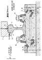
- FIG. 2 shows the device, wherein a wheel 2 of a rail vehicle, not shown in the drawing, rests on the end face 1b of the rail 1 and touches the side flank 1c of the rail head 1d with the wheel flange 2a. Occurring horizontal loads P H and vertical loads P V as well as the proportional weight, which results from the weight of the rail vehicle, and the weight of the Payload composed, are transferred from the wheel 2 to the rail head 1d of the rail 1.
- the stabilizers 10 located closer to the center of the track system are relieved when a load occurs.
- the essentially horizontally acting loads P H which are caused by the managers of the rail vehicles when driving on curve sections, are absorbed by the elastic elements 9b, 9d arranged parallel to the vertical.
- the elastic elements 9b, 9d are supported on the flanks 4b, 7b, 5b, 8b.
Landscapes
- Engineering & Computer Science (AREA)
- Architecture (AREA)
- Civil Engineering (AREA)
- Structural Engineering (AREA)
- Mechanical Engineering (AREA)
- Railway Tracks (AREA)
- Bearings For Parts Moving Linearly (AREA)
Abstract
Description
Die Erfindung betrifft eine Einrichtung zum Lagern von Schienen einer Gleisanlage für Schienenfahrzeuge mit Lagerplatte und Lagerbett, wobei sich Lagerplatte und Lagerbett unter Zwischenlage zumindest bereichsweise angeordneter elastischer Elemente über eine in Schienenlängsrichtung verlaufende, ineinandergreifende Profilierung abstützen und wobei die Profilierung in Schienenlängsrichtung verlaufende Flanken aufweist, von denen wenigstens zwei unter einem nach oben zur Schiene hin offenen, von 90° gegenüber einer Senkrechten zur Ebene der Gleisanlage abweichenden Winkel verlaufen.The invention relates to a device for storing rails of a track system for rail vehicles with a bearing plate and a bearing bed, wherein the bearing plate and the bearing bed, with the interposition of at least partially arranged elastic elements, are supported by an interlocking profile running in the longitudinal direction of the rail and the profile having flanks running in the longitudinal direction of the rail at least two of which extend at an angle that is open towards the rail and deviates from 90 ° with respect to a perpendicular to the plane of the track system.
Beim Befahren von Gleisanlagen mittels Schienenfahrzeugen entstehen abhängig vom Gewicht der Schienenfahrzeuge und von der Geschwindigkeit, mit welcher die Schienenfahrzeuge die Gleisanlage befahren unterschiedlich hohe Stossbeanspruchungen, Geräusche und insbesondere in Kurven Querkräfte. Um die Stossbeanspruchungen zu dämpfen, die Geräusche zu reduzieren und die Querkräfte abzufangen, sind Lagereinrichtungen bekannt, die aus Lagerplatte und Lagerbett bestehen, wobei eine Schiene auf der Lagerplatte befestigt ist und zwischen Lagerplatte und Lagerbett elastische Elemente angeordnet sind.When driving on track systems by means of rail vehicles, depending on the weight of the rail vehicles and the speed at which the rail vehicles drive on the track system, shock loads, noises and, in particular, lateral forces in curves are high. In order to dampen the impact loads, reduce the noise and absorb the transverse forces, bearing devices are known which consist of a bearing plate and a bearing bed, a rail being fastened to the bearing plate and elastic elements being arranged between the bearing plate and the bearing bed.
Speziell in Kurvenabschnitten einer Gleisanlage entstehen zusätzlich zu den Belastungen, die aus dem Gewicht des Schienenfahrzeuges resultieren, hohe Querkräfte, die durch die Führungskräfte der Schienenfahrzeuge entstehen. Diese höhere Belastung in Kurvenabschnitten der Gleisanlage führt zu starker Beanspruchung von Lagerplatte und Lagerbett.Especially in curve sections of a track system, in addition to the loads that result from the weight of the rail vehicle, high lateral forces are created by the managers of the rail vehicles. This higher load in curve sections of the track system leads to heavy stress on the bearing plate and bearing bed.
Durch eine gezielte Anordnung von elastischen Elementen zwischen der Lagerplatte und dem Lagerbett kann beim Auftreten einer Belastung das vertikale Bewegungsverhalten der Lagerplatte gesteuert werden. Durch die Ausbildung dieser elastischen Elemente in bestimmten geometrischen Formen, kann deren Elastizitätsverhalten beeinflusst werden.Through a targeted arrangement of elastic elements between the bearing plate and the bed can occur the load, the vertical movement behavior of the bearing plate can be controlled. Through the formation of these elastic elements in certain geometric shapes, their elasticity behavior can be influenced.
Eine Einrichtung zum Lagern von Schienen zeigt beispielsweise die DE-OS 30 30 936 bei der die Schiene auf einer Lagerplatte befestigt ist, die sich über eine Profilierung unter Zwischenlage elastischer Elemente gegen ein Lagerbett abstützt.A device for storing rails is shown, for example, in DE-OS 30 30 936, in which the rail is fastened to a bearing plate, which is supported against a bearing bed by means of profiling with the interposition of elastic elements.
Der Querschnitt der Profilierung ist im wesentlichen trapezförmig ausgebildet. Das bedeutet, dass die elastischen Elemente schräg zueinander angeordnet sind und somit einen Winkel bilden, der nach oben hin zur Schiene offen ist. Die der Mitte der Gleisanlage näher liegenden elastischen Elemente bilden mit einer Senkrechten zur Ebene der Gleisanlage einen kleineren Winkel, als die auf der Aussenseite der Gleisanlage angeordneten elastischen Elemente.The cross section of the profiling is essentially trapezoidal. This means that the elastic elements are arranged at an angle to each other and thus form an angle that is open towards the top of the rail. The elastic elements closer to the center of the track system form a smaller angle with a perpendicular to the plane of the track system than the elastic elements arranged on the outside of the track system.
Diese bekannte Einrichtung weist den Nachteil auf, dass die Lagerplatte, abhängig von der Belastungsrichtung entweder zur Mitte oder zur Aussenseite der Gleisanlage hin in eine geneigte Stellung gegenüber dem Lagerbett kippen kann. Eine Neigung der Lagerplatte zur Aussenseite der Gleisanlage hin bewirkt einen im wesentlichen horizontalen Versatz des Schienenkopfes zur Aussenseite. Damit wird eine unerwünschte Spurerweiterung erreicht, die nebst einem erhöhten Verschleiss bei einem eventuell auftretenden Schienenbruch in einem Kurvenabschnitt der Gleisanlagen zu einer Entgleisung des Schienenfahrzeuges führen kann. Die Aufnahme von Führungskräften ist nicht mehr möglich.This known device has the disadvantage that, depending on the direction of loading, the bearing plate can tip either towards the center or towards the outside of the track system into an inclined position relative to the bearing bed. An inclination of the bearing plate towards the outside of the track system results in an essentially horizontal offset of the rail head to the outside. In this way, an undesired widening of the track is achieved which, in addition to increased wear and tear in the event of a rail breakage occurring in a curve section of the track systems, can result in derailment of the rail vehicle. Managers can no longer be accepted.
Ein weiterer Nachteil dieser bekannten Einrichtung besteht darin, dass sich die Lagerplatte beim Auftreten von hohen, nur in vertikaler Richtung wirkenden Kräften sehr stark zur Mitte der Gleisanlage neigt, wodurch der Schienenkopf eine grosse horizontale Bewegung zur Mitte der Gleisanlage ausführt. Dies bewirkt eine deutliche Verengung der Spur.Another disadvantage of this known device is that the bearing plate tends very strongly towards the center of the track system when high forces acting only in the vertical direction occur, as a result of which the rail head executes a large horizontal movement towards the center of the track system. This causes a clear narrowing of the track.
Spurverengungen in Gleisanlagen rufen hohen Verschleiss im Bereich der Radflansche und im Bereich der Seitenflanken der Schienenköpfe sowie einen hohen Rollwiderstand und Geräuschentwicklung hervor.Track narrowing in track systems cause high wear in the area of the wheel flanges and in the area of the side flanks of the rail heads as well as high rolling resistance and noise.
Der Erfindung liegt die Aufgabe zugrunde, eine Einrichtung zum Lagern von Schienen zu schaffen, die unabhängig von der Belastung auch in Kurvenabschnitten die Beibehaltung der Spur gewährleistet.The invention has for its object to provide a device for storing rails, which ensures that the track is maintained regardless of the load even in curve sections.
Erfindungsgemäss wird dies dadurch erreicht, dass die Winkel zur Mitte der Gleisanlage hin offen sind und im Winkelmass von der gegen die Mitte der Gleisanlage gerichteten Innenseite der Schienen zur Aussenseite der Schienen hin zunehmen.This is achieved according to the invention in that the angles to the center of the track system are open and increase in angle from the inside of the rails directed towards the center of the track system to the outside of the rails.
Aufgrund der winkeligen Anordnung der Flanken und der elastischen Elemente zwischen Lagerbett und Lagerplatte wird die Möglichkeit geschaffen, dass die Schiene mit der Lagerplatte um einen virtuellen Pol schwenken kann, wobei dieser Pol bei jeder Schiene auf der Aussenseite der Gleisanlage, etwa in der Höhe des Schienenkopfes liegt.Due to the angular arrangement of the flanks and the elastic elements between the bearing bed and the bearing plate, the possibility is created that the rail with the bearing plate can pivot about a virtual pole, this pole for each rail on the outside of the track system, approximately at the height of the rail head lies.
Dies führt dazu, dass die aus dem Gewicht des Schienenfahrzeuges und den auftretenden Querkräften in Kurvenabschnitten resultierende Belastung einen Schwenkvorgang der Lagerplatte und der auf der Lagerplatte befestigten Schiene bewirkt, wobei sich die Lagerplatte zur Mitte der Gleisanlage neigt. Während des Schwenkvorganges bewegt sich die Lagerplatte nicht nur im wesentlichen vertikal zu der Profilierung des Lagerbettes, sondern auch horizontal zur Aussenseite der Gleisanlage. Dadurch wird der beim Schwenkvorgang der Schiene entstehende, horizontale Versatz des Schienenkopfes kompensiert. Der Schienenkopf der Schiene bleibt somit in Bezug auf seine horizontale Lage stabil. Eine sich nachteilig und teilweise gefährlich auswirkende Spurerweiterung der Gleisanlage wird somit verhindert.This leads to the fact that the load resulting from the weight of the rail vehicle and the transverse forces occurring in curve sections causes the bearing plate and the rail fastened to the bearing plate to pivot, the bearing plate tilting towards the center of the track system. During the swiveling process, the bearing plate not only moves essentially vertically to the profiling of the bed, but also horizontally to the outside of the track system. This compensates for the horizontal offset of the rail head that occurs during the swiveling process of the rail. The rail head of the rail thus remains stable with respect to its horizontal position. This prevents a disadvantageous and sometimes dangerous track widening of the track system.
Der Schwenkvorgang der Lagerplatte gegenüber dem Lagerbett kann beispielsweise durch die Hilfe von Lagerelementen wie Gleitlager, Rollen oder Kugeln unterstützt werden, die jeweils zwischen den Flanken der Profilierung von Lagerplatte und Lagerbett angeordnet sind. Dabei werden die zwischen der Lagerplatte und dem Lagerbett angeordneten elastischen Elemente durch die auftretende Belastung unterschiedlich stark zusammengedrückt.The pivoting process of the bearing plate with respect to the bearing bed can be supported, for example, by the aid of bearing elements such as slide bearings, rollers or balls, which are each arranged between the flanks of the profiling of the bearing plate and the bearing bed. The elastic elements arranged between the bearing plate and the bearing bed are compressed to different extents by the stress that occurs.
Versuche haben gezeigt, dass der Schwenkvorgang zwischen Lagerplatte und Lagerbett besonders gut erfolgt, wenn vorzugsweise die Winkel der Flanken zur Senkrechten 5° bis 85° betragen.Experiments have shown that the pivoting process between the bearing plate and the bearing bed takes place particularly well if the angles of the flanks to the vertical are preferably 5 ° to 85 °.
Zweckmässigerweise weist die Profilierung weitere im wesentlichen senkrecht zur Ebene der Gleisanlagen verlaufende Flanken auf. Diese Flanken haben im wesentlichen die Aufgabe, die auftretenden Querkräfte, die im wesentlichen durch die Führungskräfte der Schienenfahrzeuge beim Befahren von Kurvenabschnitten entstehen, aufzunehmen.The profiling expediently has further flanks which run essentially perpendicular to the plane of the track systems. These flanks essentially have the task of absorbing the transverse forces that occur, which essentially arise from the managers of the rail vehicles when driving on curve sections.
Zweckmässigerweise sind zumindest bei einem Teil der Flanken zwischen Lagerplatte und Lagerbett elastische Elemente angeordnet. Die elastischen Elemente besitzen die Eigenschaft, Querkräfte elastischer aufnehmen zu können als Druckkräfte. Durch die Anordnung von Flanken mit unterschiedlichen Winkeln kann somit beim Auftreten einer Belastung, das unterschiedliche Bewegungsverhalten der Flanken gegenüber den elastischen Elementen gesteuert werden. Je nach Anordnung der Flanken können somit an den elastischen Elementen unterschiedliche Querkräfte angreifen. Um den gewünschten Schwenkvorgang zwischen Lagerplatte und Lagerbett erzielen zu können, wir dieses entsprechende Bewegungsverhalten der Flanken gegenüber den elastischen Elementen ausgenützt.Expediently, elastic elements are arranged at least in part of the flanks between the bearing plate and the bearing bed. The elastic elements have the property of being able to absorb transverse forces more elastically than compressive forces. By arranging flanks with different angles, the different movement behavior of the flanks with respect to the elastic elements can thus be controlled when a load occurs. Depending on the arrangement of the flanks, different transverse forces can act on the elastic elements. In order to be able to achieve the desired pivoting process between the bearing plate and the bearing bed, we use this corresponding movement behavior of the flanks in relation to the elastic elements.
Im Bereich der Profilierung können die elastischen Elemente auch nur derart angeordnet sein, dass sie das Zurückdrücken der Lagerplatte in die normale Position gewährleisten.In the area of the profiling, the elastic elements can also only be arranged in such a way that they ensure that the bearing plate is pushed back into the normal position.
Vorzugsweise bestehen die elastischen Elemente aus synthetischem Gummi, natürlichem Gummi, Kork, Polyurethan oder Polysulfid. Diese Materialien besitzen die Eigenschaft, gegenüber auftretenden Querkräften elastisch zu wirken und gegenüber Druckkräften in ihrer Form stabiler zu bleiben.The elastic elements are preferably made of synthetic rubber, natural rubber, cork, polyurethane or polysulfide. These materials have the property of being elastic against transverse forces and of being more stable in their form against compressive forces.
Zweckmässigerweise weisen die elastischen Elemente einen rechteckigen, quadratischen, trapezförmigen, runden oder polygonalen Querschnitt auf. Je nach Art der Ausbildung der Profilierung an der Lagerplatte und am Lagerbett können die elastischen Elemente die zuvor genannten Querschnitte aufweisen.The elastic elements expediently have a rectangular, square, trapezoidal, round or polygonal cross section. Depending on the type of profiling on the bearing plate and on the bed, the elastic elements can have the cross sections mentioned above.
Wie schon in der Beschreibung weiter vorne darauf hingewiesen wurde, können bestimmte Elastizitätsverhalten von elastischen Elementen durch eine entsprechende Formgebung der elastischen Elemente erreicht werden.As was pointed out earlier in the description, certain elastic behavior of elastic elements can be achieved by appropriate shaping of the elastic elements.
Vorteilhafterweise ist die Profilierung von wenigstens zwei zahnförmigen Leisten an der Lagerplatte und entsprechenden Ausnehmungen an dem Lagerbett gebildet. Die als zahnförmige Leisten ausgebildete Profilierung erstreckt sich parallel zur Schienenlängsachse. Eine Einrichtung zum Lagern von Schienen mit einer derartig ausgebildeten zwei zahnförmige Leisten aufweisenden Profilierung ist gegenüber den auftretenden Kräften sehr lagestabil, da die zahnförmigen Leisten im wesentlichen weit auseinander jeweils im Bereich der Aussenseite der Lagerplatte bzw Lagerbett angeordnet sind. Die auf der gegenüberliegenden Seite der Lagerplatte befestigte Schiene befindet sich somit im wesentlichen zwischen beiden zahnförmigen Leisten. Anstelle der Anordnung von zwei zahnförmigen Leisten können auch mehrere, über die im rechten Winkel zur Schienenlängsachse gemessene Breite von Lagerplatte und Lagerbett verteilte, zueinander parallel verlaufende, zahnförmige Leisten vorgesehen sein.The profiling is advantageously formed by at least two tooth-shaped strips on the bearing plate and corresponding recesses on the bearing bed. The profiling designed as tooth-shaped strips extends parallel to the longitudinal axis of the rail. A device for storing rails with a profile formed in this way and having two tooth-shaped strips is very stable in relation to the forces which occur, since the tooth-shaped strips are arranged essentially far apart in the region of the outside of the bearing plate or bearing bed. The rail fastened on the opposite side of the bearing plate is thus essentially between the two toothed strips. Instead of the arrangement of two tooth-shaped strips, a plurality of tooth-shaped strips distributed parallel to one another and distributed over the width of the bearing plate and bearing bed measured at right angles to the longitudinal axis of the rail can also be provided.
Die Erfindung wird anhand eines Ausführungsbeispieles, das im Querschnitt eine Einrichtung zum Lagern von Schienen zeigt, näher erläutert. Es zeigen:
- Fig. 1
- die Einrichtung in unbelastetem Zustand;
- Fig. 2
- die Einrichtung gemäss Fig. 1 in belastetem Zustand;
- Fig. 1
- the facility in an unloaded condition;
- Fig. 2
- 1 in the loaded state;
Die Lagerplatte 3 und das Lagerbett 6 weisen eine ineinandergreifende Profilierung auf, die im dargestellten Beispiel zwei zahnförmige Leisten 4, 5 an der Lagerplatte 3 und zwei Ausnehmungen 7, 8 im Lagerbett 6 aufweist. Die zahnförmigen Leisten 4, 5 ragen unter Zwischenlage von elastischen Elementen 9a, 9b, 9c, 9d in die Ausnehmungen 7, 8 des Lagerbettes 6, das auf einem festen Untergrund U, beispielsweise einer Schienenschwelle mittels nicht näher dargestellten Befestigungselementen befestigt ist.The bearing plate 3 and the
Befindet sich die Gleisanlage nicht unter Belastung, wie gemäss Fig. 1 dargestellt, so halten die elastischen Elemente 9a, 9b, 9c, 9d die Lagerplatte 3 und das Lagerbett 6 im ursprünglichen Abstand voneinander.If the track system is not under load, as shown in FIG. 1, the
Die zahnförmigen Leisten 4, 5 und die Ausnehmungen 7, 8 weisen Flanken 4a, 7a, 5a, 8a auf, die unter einem von 90° abweichenden Winkel zu einer Senkrechten zur Ebene der Gleisanlage verlaufen. Die Flanken 4a, 7a, 5a, 8a sind derart schräg angeordnet, dass die unterschiedlichen Winkel zur Mitte der Gleisanlage hin offen sind und im Winkelmass von der zur Mitte der Gleisanlage gerichteten Innenseite der Schiene 1 zur Aussenseite der Schiene 1 hin zunehmen. Somit sind die der Mitte der Gleisanlage näherliegenderen Flanken 4a, 7a in Bezug auf eine Horizontale steiler angeordnet als die Flanken 5a, 8a, die weiter von der der Mitte der Gleisanlage abliegen.The tooth-shaped strips 4, 5 and the
Die der Mitte der Gleisanlage näherliegende zahnförmige Leiste 4 ist im wesentlichen spitzförmiger ausgebildet, als die zahnförmige Leiste 5. Die elastischen Elemente 9a, 9b, 9c, 9d besitzen die Eigenschaft, auf Querkräfte elastischer zu reagieren, als auf Druckkräfte.The tooth-shaped bar 4 which is closer to the center of the track system is essentially more pointed than the tooth-shaped bar 5. The
Um eine vertikale Sicherung der Lagerplatte 3 und somit der Schiene 1 zu gewährleisten, umgreift das Lagerbett 6 die Lagerplatte 3 mit umgreifenden Teilen 6c, 6d wenigstens teilweise. Damit ein Herausspringen der Lagerplatte 3 aus dem Lagerbett 6 und die Korrosion sowie die Verschmutzung im Bereich der Profilierung verhindert wird, befinden sich elastische Stabilisatoren 10 zwischen den mit dem Lagerbett 6 verbundenen, die Lagerplatte 3 umgreifenden Teilen 6c, 6d und der Lagerplatte 3.In order to ensure vertical securing of the bearing plate 3 and thus of the
Damit die Einrichtung zum Lagern von Schienen 1 entsprechenden Widerstand gegen auftretenden Durchschub bilden kann, ist die Lagerplatte 3 derart ausgebildet, dass sie das Lagerbett 6 in Längsrichtung der Schienen 1 überragt, wobei sich der überragende Teil der Lagerplatte 3 vertikal nach unten erstreckt und das Lagerbett 6 teilweise überlappt. Zwischen Lagerplatte 3 und Lagerbett 6 sind zusätzlich elastische Elemente angeordnet, die den entsprechenden Widerstand gegen Durchschub bilden. Das Uebergreifen des Lagerbettes 6 durch die Lagerplatte 3 in Längsrichtung der Schienen 1 ist in nicht dargestellt.So that the device for storing
Die Fig. 2 zeigt die Einrichtung, wobei ein Rad 2 eines zeichnerisch nicht dargestellten Schienenfahrzeuges auf der Stirnfläche 1b der Schiene 1 aufliegt und mit dem Radflansch 2a die Seitenflanke 1c des Schienenkopfes 1d berührt. Auftretende horizontale Belastungen PH und vertikale Belastungen PV sowie das anteilsmässige Gewicht, das sich aus dem Eigengewicht des Schienenfahrzeuges, und dem Gewicht der Zuladung zusammensetzt, werden vom Rad 2 auf den Schienenkopf 1d der Schiene 1 übertragen.2 shows the device, wherein a
Im Bereich der im wesentlichen spitzförmiger ausgebildeten zahnförmigen Leiste 4 treten gegenüber den elastischen Elementen 9a, 9b höhere Querkräfte auf, als in den elastischen Elementen 9c, 9d im Bereich der Zahnleiste 5. Durch die unterschiedliche Querkraft auf die elastischen Elemente 9a, 9b, 9c, 9d entsteht im Bereich der spitzförmiger augebildeten zahnförmigen Leiste 4 bei Belastung eine grössere Bewegung der Lagerplatte 3 gegenüber den elastischen Elementen 9a, 9b als im Bereich der zahnförmigen Leiste 5. Dabei neigt sich die Lagerplatte 3 zur Mitte der Gleisanlage, und die elastischen Elemente 9a, 9b, 9c, 9d verformen sich aufgrund der auftretenden Querkräfte und Druckkräfte.In the area of the tooth-shaped bar 4, which is essentially pointed, there are higher transverse forces compared to the
Im Gegensatz zu den im Bereich der Aussenseite der Gleisanlage angeordneten, sich verformenden Stabilisatoren 10 werden die der Mitte der Gleisanlage näher liegendenden Stabilisatoren 10 beim Auftreten einer Belastung entlastet.In contrast to the deforming
Die im wesentlichen horizontal wirkenden Belastungen PH, die durch die Führungskräfte der Schienenfahrzeuge beim Befahren von Kurvenabschnitten entstehen, werden von den parallel zur Senkrechten angeordneten elastischen Elementen 9b, 9d aufgenommen. Die elastischen Elemente 9b, 9d stützen sich dabei an den Flanken 4b, 7b, 5b, 8b ab.The essentially horizontally acting loads P H , which are caused by the managers of the rail vehicles when driving on curve sections, are absorbed by the
Durch das einseitige, stärkere Eintauchen der zahnförmigen Leiste 4 in die Ausnehmung 7, erfolgt ebenfalls eine Neigung der auf der Lagerplatte 3 befestigten Schiene 1, deren Schienenkopf 1d im wesentlichen nur vertikal versetzt wird.Due to the one-sided, stronger immersion of the tooth-shaped bar 4 in the
Claims (7)
Applications Claiming Priority (4)
| Application Number | Priority Date | Filing Date | Title |
|---|---|---|---|
| DE4206207 | 1992-02-28 | ||
| DE4206207 | 1992-02-28 | ||
| DE4220799 | 1992-06-25 | ||
| DE4220799A DE4220799A1 (en) | 1992-02-28 | 1992-06-25 | DEVICE FOR STORING RAILS |
Publications (2)
| Publication Number | Publication Date |
|---|---|
| EP0557716A1 true EP0557716A1 (en) | 1993-09-01 |
| EP0557716B1 EP0557716B1 (en) | 1996-02-28 |
Family
ID=25912311
Family Applications (1)
| Application Number | Title | Priority Date | Filing Date |
|---|---|---|---|
| EP93100851A Expired - Lifetime EP0557716B1 (en) | 1992-02-28 | 1993-01-21 | Supporting device for railway rails |
Country Status (3)
| Country | Link |
|---|---|
| US (1) | US5346131A (en) |
| EP (1) | EP0557716B1 (en) |
| DE (2) | DE4220799A1 (en) |
Cited By (5)
| Publication number | Priority date | Publication date | Assignee | Title |
|---|---|---|---|---|
| EP0751257A2 (en) * | 1995-05-18 | 1997-01-02 | Transformados Del Norte, S.A. | Improved pan for railway line double-block sleepers |
| CN102296493A (en) * | 2011-07-15 | 2011-12-28 | 洛阳双瑞橡塑科技有限公司 | Non-ballast track vibration damping structure with uniform and continuous rigidity |
| EP2363529A3 (en) * | 2010-02-25 | 2012-12-05 | Vossloh-Werke GmbH | System for attaching a rail |
| CN103603237A (en) * | 2013-12-02 | 2014-02-26 | 北京九州一轨隔振技术有限公司 | Floating type track bed turnout |
| EP3418448A1 (en) * | 2017-06-23 | 2018-12-26 | Delkor Rail Pty Ltd | Mounting device |
Families Citing this family (10)
| Publication number | Priority date | Publication date | Assignee | Title |
|---|---|---|---|---|
| US5551632A (en) * | 1994-11-02 | 1996-09-03 | Illinois Tool Works Inc. | Elastomeric pad between railroad rail and railroad tie |
| US5551633A (en) * | 1994-11-02 | 1996-09-03 | Illinois Tool Works, Inc. | Elastomeric pad between railroad rail and railroad tie |
| US5549245A (en) * | 1994-11-02 | 1996-08-27 | Illinois Tool Works Inc. | Composite pad useful between railroad rail and railroad tie |
| DE19746587C1 (en) * | 1997-10-22 | 1999-02-11 | Heitkamp Gmbh Bau | Rail support |
| JP2004536002A (en) * | 2001-07-30 | 2004-12-02 | インベンテイオ・アクテイエンゲゼルシヤフト | Method and apparatus for mounting guide rails |
| DE10152380A1 (en) * | 2001-10-28 | 2003-06-26 | Pieper Siegfried | Device for detecting forces and changes on wheels of rail vehicles |
| US20080121732A1 (en) * | 2006-11-28 | 2008-05-29 | Yung-Yi Chen | Laminated tie plate |
| US8210444B2 (en) * | 2010-10-18 | 2012-07-03 | Osler Wilbur F | Direct fixation track-mounting assembly |
| EP2821358B1 (en) * | 2013-07-03 | 2016-11-30 | Kone Corporation | Guide rail alignment system for elevators |
| CN111021156A (en) * | 2019-12-25 | 2020-04-17 | 重庆艾博瑞威轨道交通设备有限公司 | Novel main and auxiliary rail pressing plate |
Citations (4)
| Publication number | Priority date | Publication date | Assignee | Title |
|---|---|---|---|---|
| FR2174007A1 (en) * | 1972-02-10 | 1973-10-12 | Japan National Railway | |
| DE2817278A1 (en) * | 1978-04-20 | 1979-10-25 | Diether Uderstaedt | Sound insulating railway rail underlay - has insulation units matching trapezium shaped deformation in interfacing base and support plates |
| GB2083111A (en) * | 1980-09-06 | 1982-03-17 | Uderstadt Diether | Sound-insulating railway track |
| DE3030936A1 (en) * | 1980-08-16 | 1982-04-01 | Clouth Gummiwerke AG, 5000 Köln | DEVICE FOR STORING RAILS FOR RAIL VEHICLES |
Family Cites Families (4)
| Publication number | Priority date | Publication date | Assignee | Title |
|---|---|---|---|---|
| GB2024289B (en) * | 1978-06-30 | 1983-03-30 | Clouth Gummiwerke Ag | Resilient rail support |
| DE3030937A1 (en) * | 1980-08-16 | 1982-03-25 | Clouth Gummiwerke AG, 5000 Köln | DEVICE FOR STORING RAILS FOR RAIL VEHICLES |
| DE3406679A1 (en) * | 1984-02-24 | 1985-09-05 | Phoenix Ag, 2100 Hamburg | Flexible bearing for rails |
| US4632308A (en) * | 1985-10-25 | 1986-12-30 | Portec, Inc. | Adjustable rail fastener assembly |
-
1992
- 1992-06-25 DE DE4220799A patent/DE4220799A1/en not_active Withdrawn
-
1993
- 1993-01-21 EP EP93100851A patent/EP0557716B1/en not_active Expired - Lifetime
- 1993-01-21 DE DE59301695T patent/DE59301695D1/en not_active Expired - Fee Related
- 1993-01-28 US US08/010,231 patent/US5346131A/en not_active Expired - Fee Related
Patent Citations (4)
| Publication number | Priority date | Publication date | Assignee | Title |
|---|---|---|---|---|
| FR2174007A1 (en) * | 1972-02-10 | 1973-10-12 | Japan National Railway | |
| DE2817278A1 (en) * | 1978-04-20 | 1979-10-25 | Diether Uderstaedt | Sound insulating railway rail underlay - has insulation units matching trapezium shaped deformation in interfacing base and support plates |
| DE3030936A1 (en) * | 1980-08-16 | 1982-04-01 | Clouth Gummiwerke AG, 5000 Köln | DEVICE FOR STORING RAILS FOR RAIL VEHICLES |
| GB2083111A (en) * | 1980-09-06 | 1982-03-17 | Uderstadt Diether | Sound-insulating railway track |
Cited By (7)
| Publication number | Priority date | Publication date | Assignee | Title |
|---|---|---|---|---|
| EP0751257A2 (en) * | 1995-05-18 | 1997-01-02 | Transformados Del Norte, S.A. | Improved pan for railway line double-block sleepers |
| EP0751257A3 (en) * | 1995-05-18 | 1997-03-26 | Transformados Del Norte S A | Improved pan for railway line double-block sleepers |
| EP2363529A3 (en) * | 2010-02-25 | 2012-12-05 | Vossloh-Werke GmbH | System for attaching a rail |
| CN102296493A (en) * | 2011-07-15 | 2011-12-28 | 洛阳双瑞橡塑科技有限公司 | Non-ballast track vibration damping structure with uniform and continuous rigidity |
| CN103603237A (en) * | 2013-12-02 | 2014-02-26 | 北京九州一轨隔振技术有限公司 | Floating type track bed turnout |
| CN103603237B (en) * | 2013-12-02 | 2016-08-17 | 北京九州一轨隔振技术有限公司 | A kind of floating type railway roadbed track switch |
| EP3418448A1 (en) * | 2017-06-23 | 2018-12-26 | Delkor Rail Pty Ltd | Mounting device |
Also Published As
| Publication number | Publication date |
|---|---|
| EP0557716B1 (en) | 1996-02-28 |
| DE59301695D1 (en) | 1996-04-04 |
| DE4220799A1 (en) | 1993-09-02 |
| US5346131A (en) | 1994-09-13 |
Similar Documents
| Publication | Publication Date | Title |
|---|---|---|
| EP0557716B1 (en) | Supporting device for railway rails | |
| DE4109971C2 (en) | Monorail underflange trolley | |
| AT401397B (en) | FASTENING DEVICE FOR RAILWAY RAILS AND FASTENING SPRINGS | |
| EP2204494A1 (en) | Elastic tensioning clamp and rail attachment for same | |
| EP0964100B1 (en) | Rolling support for the moving blade cooperating with the fixed rail of a switch | |
| EP0151160B1 (en) | Articulated butt joint for suspended rails of a monorail suspended railway | |
| DE4219472C2 (en) | Device for storing rails | |
| AT511068B1 (en) | DEVICE FOR VIBRATION DAMPING AND FOR CHANGING LONGITUDINAL STIFFNESS | |
| EP2493742A2 (en) | Track maintenance vehicle | |
| EP1246970B1 (en) | Fastening device for rails | |
| WO2011047881A1 (en) | Structure bearing | |
| DE3637281A1 (en) | Spring bracket which can be fixed on the frame of a chassis | |
| EP1060097B1 (en) | Rail brake, especially a holding brake | |
| WO1994002682A1 (en) | Roller device | |
| DE7739969U1 (en) | Leaf spring | |
| EP0742132B1 (en) | Device for supporting the body of a railway vehicle on its underframe | |
| DE19812795C1 (en) | Slide plate for railway points | |
| AT146702B (en) | Bogie for rail vehicles. | |
| WO1998021411A1 (en) | Substructure for a railway vehicle track formed from rails | |
| EP0952071B1 (en) | Bogies for crawler | |
| DE102021205982A1 (en) | Bridging structure for supporting at least one rail of a railway track in the area of a building joint and railway structure with such a bridging structure | |
| AT406855B (en) | PORTAL CHASSIS FOR RAIL VEHICLES | |
| DE102022120816A1 (en) | Swing sliding door guide device without guide rail | |
| DE3413594C1 (en) | Guide element for a haulage means in winding and inclined-conveyor installations | |
| DE102014006774A1 (en) | Truck mixer for flowable media, especially concrete |
Legal Events
| Date | Code | Title | Description |
|---|---|---|---|
| PUAI | Public reference made under article 153(3) epc to a published international application that has entered the european phase |
Free format text: ORIGINAL CODE: 0009012 |
|
| AK | Designated contracting states |
Kind code of ref document: A1 Designated state(s): CH DE FR GB LI |
|
| 17P | Request for examination filed |
Effective date: 19930914 |
|
| 17Q | First examination report despatched |
Effective date: 19941125 |
|
| GRAA | (expected) grant |
Free format text: ORIGINAL CODE: 0009210 |
|
| AK | Designated contracting states |
Kind code of ref document: B1 Designated state(s): CH DE FR GB LI |
|
| GBT | Gb: translation of ep patent filed (gb section 77(6)(a)/1977) |
Effective date: 19960226 |
|
| REF | Corresponds to: |
Ref document number: 59301695 Country of ref document: DE Date of ref document: 19960404 |
|
| ET | Fr: translation filed | ||
| PLBE | No opposition filed within time limit |
Free format text: ORIGINAL CODE: 0009261 |
|
| STAA | Information on the status of an ep patent application or granted ep patent |
Free format text: STATUS: NO OPPOSITION FILED WITHIN TIME LIMIT |
|
| PGFP | Annual fee paid to national office [announced via postgrant information from national office to epo] |
Ref country code: GB Payment date: 19970110 Year of fee payment: 5 |
|
| 26N | No opposition filed | ||
| PG25 | Lapsed in a contracting state [announced via postgrant information from national office to epo] |
Ref country code: GB Free format text: LAPSE BECAUSE OF NON-PAYMENT OF DUE FEES Effective date: 19980121 |
|
| GBPC | Gb: european patent ceased through non-payment of renewal fee |
Effective date: 19980121 |
|
| PGFP | Annual fee paid to national office [announced via postgrant information from national office to epo] |
Ref country code: DE Payment date: 20010115 Year of fee payment: 9 |
|
| PGFP | Annual fee paid to national office [announced via postgrant information from national office to epo] |
Ref country code: FR Payment date: 20010125 Year of fee payment: 9 |
|
| PGFP | Annual fee paid to national office [announced via postgrant information from national office to epo] |
Ref country code: CH Payment date: 20010219 Year of fee payment: 9 |
|
| PG25 | Lapsed in a contracting state [announced via postgrant information from national office to epo] |
Ref country code: LI Free format text: LAPSE BECAUSE OF NON-PAYMENT OF DUE FEES Effective date: 20020131 Ref country code: CH Free format text: LAPSE BECAUSE OF NON-PAYMENT OF DUE FEES Effective date: 20020131 |
|
| PG25 | Lapsed in a contracting state [announced via postgrant information from national office to epo] |
Ref country code: DE Free format text: LAPSE BECAUSE OF NON-PAYMENT OF DUE FEES Effective date: 20020801 |
|
| REG | Reference to a national code |
Ref country code: CH Ref legal event code: PL |
|
| PG25 | Lapsed in a contracting state [announced via postgrant information from national office to epo] |
Ref country code: FR Free format text: LAPSE BECAUSE OF NON-PAYMENT OF DUE FEES Effective date: 20020930 |
|
| REG | Reference to a national code |
Ref country code: FR Ref legal event code: ST |