EP0751257A2 - Improved pan for railway line double-block sleepers - Google Patents
Improved pan for railway line double-block sleepers Download PDFInfo
- Publication number
- EP0751257A2 EP0751257A2 EP96500063A EP96500063A EP0751257A2 EP 0751257 A2 EP0751257 A2 EP 0751257A2 EP 96500063 A EP96500063 A EP 96500063A EP 96500063 A EP96500063 A EP 96500063A EP 0751257 A2 EP0751257 A2 EP 0751257A2
- Authority
- EP
- European Patent Office
- Prior art keywords
- block
- pan
- ridges
- railway line
- double
- Prior art date
- Legal status (The legal status is an assumption and is not a legal conclusion. Google has not performed a legal analysis and makes no representation as to the accuracy of the status listed.)
- Granted
Links
Images


Classifications
-
- E—FIXED CONSTRUCTIONS
- E01—CONSTRUCTION OF ROADS, RAILWAYS, OR BRIDGES
- E01B—PERMANENT WAY; PERMANENT-WAY TOOLS; MACHINES FOR MAKING RAILWAYS OF ALL KINDS
- E01B1/00—Ballastway; Other means for supporting the sleepers or the track; Drainage of the ballastway
- E01B1/002—Ballastless track, e.g. concrete slab trackway, or with asphalt layers
- E01B1/005—Ballastless track, e.g. concrete slab trackway, or with asphalt layers with sleeper shoes
-
- E—FIXED CONSTRUCTIONS
- E01—CONSTRUCTION OF ROADS, RAILWAYS, OR BRIDGES
- E01B—PERMANENT WAY; PERMANENT-WAY TOOLS; MACHINES FOR MAKING RAILWAYS OF ALL KINDS
- E01B2204/00—Characteristics of the track and its foundations
- E01B2204/01—Elastic layers other than rail-pads, e.g. sleeper-shoes, bituconcrete
Definitions
- the present Patent application relates to an improved pan for railway line double-block sleepers which, in addition to the function for which it was designed, affords a number of advantages discussed hereinafter, and others that are inherent in its organisation and construction.
- STEDEF type lines without ballast is known since the year 1963, based upon the principle of mounting a sleeper comprising two concrete blocks with a modified base in which a rubber pan is housed including symmetrical ridges on its sides, and having a foam mattress on the bottom end to prevent transmission of vibrations.
- This double-block sleeper is provided with a steel spacing bar which is primarily designed to maintain the gage upon mounting, and further to absorb the lateral stresses originating in the wheel-rail interaction.
- the proposer of the present patent application has devised improvements for rubber pans of the kind located at the modified base of a double-block sleeper, with which a wholly different performance is achieved with regard to the turning torque resulting from the lateral stresses referred to in the above section, whereby the spacing bar can be removed without risking derailment.
- the improvements lie in configuring an asymmetrical pan with its side walls having a variable rigidity that lies in a greater rubber mass at areas that are placed under a greater compression due to the lateral stresses under a passing train.
- the asymmetrical pan subject of the present invention has varying rigidities on its sides, directly in proportion to the stresses applied by the concrete block due to the wheel-rail interaction.
- the improved pan in accordance with the present Patent application, provides the advantages described above as well as others that will follow easily from the embodiment described hereinafter in detail for an easy understanding of the features set out above, concurrently giving a number of details and attaching to the present specification, to such end, some drawings showing a practical example of the object of the present invention that is meant to illustrate and not to limit its scope.
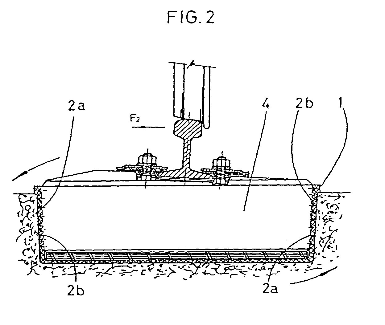
- Figures 1 and 2 are embodiments of the current state of the art, and respectively illustrate the performance of a double-block sleeper with a spacing bar and the performance of the block of a sleeper of the same kind, albeit without a spacing bar, when a train is running thereon.
- Figure 3 is a longitudinal section of an asymmetrical pan in accordance with the object of the invention.
- Figures 4 and 5 show two cross sections along A-A and B-B, in accordance with the preceding figure.
- FIGS. 6 and 7 are sections equivalent to the above of an asymmetrical pan in accordance with the invention, made in accordance with an alternative embodiment, which figures respectively illustrate the outer front and inner front of the pan.
- the pan subject of the invention is of the kind comprising a rubber part, generally designated -1-, as shown in figures 1 and 2, provided with symmetrical ridges -2- and having a foam mattress -3- located on the lower inner base, which pan is designed to be housed in the modified base of a sleeper comprising two concrete blocks -4- connected by means of a steel spacing bar -5- and which is designed to avoid the transmission of vibrations.
- the spacing bar -5- is designed to maintain the gage upon mounting and absorb the lateral stresses F 3 resulting from the wheel-rail interaction, to avoid gage widenings of the rails and prevent derailments. If the spacing bar -5- is removed, for the reasons aforesaid, and the sleeper is made as illustrated in figure 2, the force F 2 , when acting upon the running rail, generates a turning torque that is transferred to the block -4-, compressing the rubber ridges -2a- and decompressing the ridges -2b- which, because of their very elastic nature, yield generating very dangerous gage widenings.
- the invention lies particularly in improvements made in rubber pans of this kind, and is based upon varying the rigidities of the rubber side walls asymmetrically, as shown in figures 3 to 7, which illustrate the object of the invention.
- the pan subject of the invention is designated -6- to distinguish it from the conventional pan -1- aforesaid.
- This pan -6- is provided with an asymmetry on the structure of its sides.
- the ridges designated -7- have less interspaces -8- and there is therefore a far greater resistance to expansion of the rubber due to compression, thereby lowering the chances of the block -4- pitching.
- the ridges designated -7a- however, have a larger number of interspaces -8a-, for they are subjected to a discharge of lateral compression.
- Figures 6 and 7 illustrate an alternative embodiment of the pan subject of the invention, in which the asymmetrical variation of the rigidities on the side walls is achieved through other means, such as by forming circular embossments -9- of large diameter at areas placed under a greater compression, and embossments -10- of lesser diameter on the surfaces subjected to a discharge of the side compression.
Abstract
Description
- The present Patent application relates to an improved pan for railway line double-block sleepers which, in addition to the function for which it was designed, affords a number of advantages discussed hereinafter, and others that are inherent in its organisation and construction.
- The use of STEDEF type lines without ballast is known since the year 1963, based upon the principle of mounting a sleeper comprising two concrete blocks with a modified base in which a rubber pan is housed including symmetrical ridges on its sides, and having a foam mattress on the bottom end to prevent transmission of vibrations. This double-block sleeper is provided with a steel spacing bar which is primarily designed to maintain the gage upon mounting, and further to absorb the lateral stresses originating in the wheel-rail interaction.
- The reason why such stresses need to be absorbed is to avoid gage widenings of the rails and thereby prevent derailment from occurring; the presence of the current spacing bar is, however, in practice a hindrance which makes it difficult for people to walk between the rails in the line, which circumstance poses a major problem when passengers must be evacuated due to a breakdown or otherwise, for they must walk between the rails and risk being injured by the spacing bars that form an integral part of current double-block sleepers.
- The elimination of spacing bars in order to solve the foregoing problem is not currently possible, since a force acting sideways on the running rail, originating when the train is running, particularly at a bend, generates a turning torque that is transferred to the concrete block, compressing the rubber ridges on one side of the pan and decompressing the ridges on the opposite side of said pan, the very elastic nature of the ridges causing them to yield, which results in very dangerous gage widenings.
- Now, therefore, no double-block sleeper without a spacing bar is known in the current state of the art which suitably reacts to the overturning torque derived from the lateral stresses caused by a train running upon the sleeper, which results in the gage widenings of the rails.
- The proposer of the present patent application has devised improvements for rubber pans of the kind located at the modified base of a double-block sleeper, with which a wholly different performance is achieved with regard to the turning torque resulting from the lateral stresses referred to in the above section, whereby the spacing bar can be removed without risking derailment.
- The improvements lie in configuring an asymmetrical pan with its side walls having a variable rigidity that lies in a greater rubber mass at areas that are placed under a greater compression due to the lateral stresses under a passing train.
- Now, therefore, the asymmetrical pan subject of the present invention, has varying rigidities on its sides, directly in proportion to the stresses applied by the concrete block due to the wheel-rail interaction.
- The improved pan, in accordance with the present Patent application, provides the advantages described above as well as others that will follow easily from the embodiment described hereinafter in detail for an easy understanding of the features set out above, concurrently giving a number of details and attaching to the present specification, to such end, some drawings showing a practical example of the object of the present invention that is meant to illustrate and not to limit its scope.
- In the drawings:
- Figures 1 and 2 are embodiments of the current state of the art, and respectively illustrate the performance of a double-block sleeper with a spacing bar and the performance of the block of a sleeper of the same kind, albeit without a spacing bar, when a train is running thereon.
- Figure 3 is a longitudinal section of an asymmetrical pan in accordance with the object of the invention.
- Figures 4 and 5 show two cross sections along A-A and B-B, in accordance with the preceding figure.
- Figures 6 and 7 are sections equivalent to the above of an asymmetrical pan in accordance with the invention, made in accordance with an alternative embodiment, which figures respectively illustrate the outer front and inner front of the pan.
- With reference to the drawings, the pan subject of the invention is of the kind comprising a rubber part, generally designated -1-, as shown in figures 1 and 2, provided with symmetrical ridges -2- and having a foam mattress -3- located on the lower inner base, which pan is designed to be housed in the modified base of a sleeper comprising two concrete blocks -4- connected by means of a steel spacing bar -5- and which is designed to avoid the transmission of vibrations.
- As noted hereinabove, the spacing bar -5- is designed to maintain the gage upon mounting and absorb the lateral stresses F3 resulting from the wheel-rail interaction, to avoid gage widenings of the rails and prevent derailments. If the spacing bar -5- is removed, for the reasons aforesaid, and the sleeper is made as illustrated in figure 2, the force F2, when acting upon the running rail, generates a turning torque that is transferred to the block -4-, compressing the rubber ridges -2a- and decompressing the ridges -2b- which, because of their very elastic nature, yield generating very dangerous gage widenings.
- The invention lies particularly in improvements made in rubber pans of this kind, and is based upon varying the rigidities of the rubber side walls asymmetrically, as shown in figures 3 to 7, which illustrate the object of the invention.
- In said figures, the pan subject of the invention is designated -6- to distinguish it from the conventional pan -1- aforesaid. This pan -6- is provided with an asymmetry on the structure of its sides. As shown in figures 3 to 5, the ridges designated -7- have less interspaces -8- and there is therefore a far greater resistance to expansion of the rubber due to compression, thereby lowering the chances of the block -4- pitching. The ridges designated -7a-, however, have a larger number of interspaces -8a-, for they are subjected to a discharge of lateral compression.
- Figures 6 and 7 illustrate an alternative embodiment of the pan subject of the invention, in which the asymmetrical variation of the rigidities on the side walls is achieved through other means, such as by forming circular embossments -9- of large diameter at areas placed under a greater compression, and embossments -10- of lesser diameter on the surfaces subjected to a discharge of the side compression.
Claims (3)
- An improved pan for railway line double-block sleepers, being of the kind comprising a single rubber body, with ridges on the side walls and a foam mattress on the bottom end, designed to be housed in the modified base of a double-block sleeper without a spacing bar, essentially characterised by having an asymmetry on its sides, affecting the top and bottom area thereof, which provides varying rigidities in such areas, directly in proportion to the stresses applied by the concrete block due to the wheel-rail interaction, in order to avoid pitching thereof and gage widening of the rails.
- An improved pan for railway line double-block sleepers, as in claim 1, characterised because the asymmetry of the sides is configured by the presence of ridges (7) provided with less interspaces (8) than the interspaces (8a) existing between the ridges (7a).
- An improved pan for railway line double-block sleepers, as in claim 1, characterised because the asymmetry of the sides is configured by the presence of embossments (9) having a greater surface area than second embossments (10), between which interspaces of greater surface area are provided.
Applications Claiming Priority (2)
| Application Number | Priority Date | Filing Date | Title |
|---|---|---|---|
| ES9500946 | 1995-05-18 | ||
| ES09500946A ES2119633B1 (en) | 1995-05-18 | 1995-05-18 | PERFECTED POT FOR CROSSROAD BIBLOCK OF VIA FERREA. |
Publications (3)
| Publication Number | Publication Date |
|---|---|
| EP0751257A2 true EP0751257A2 (en) | 1997-01-02 |
| EP0751257A3 EP0751257A3 (en) | 1997-03-26 |
| EP0751257B1 EP0751257B1 (en) | 2001-08-29 |
Family
ID=8290385
Family Applications (1)
| Application Number | Title | Priority Date | Filing Date |
|---|---|---|---|
| EP96500063A Expired - Lifetime EP0751257B1 (en) | 1995-05-18 | 1996-05-17 | Improved pan for railway line double-block sleepers |
Country Status (4)
| Country | Link |
|---|---|
| EP (1) | EP0751257B1 (en) |
| AT (1) | ATE204938T1 (en) |
| DE (1) | DE69614781D1 (en) |
| ES (1) | ES2119633B1 (en) |
Cited By (3)
| Publication number | Priority date | Publication date | Assignee | Title |
|---|---|---|---|---|
| WO1999016976A1 (en) * | 1997-09-26 | 1999-04-08 | Phoenix Aktiengesellschaft | Rail system |
| DE202012006937U1 (en) * | 2012-07-18 | 2013-10-21 | Imes-Icore Gmbh | Linear feed unit |
| CN112626931A (en) * | 2020-12-22 | 2021-04-09 | 中国铁路设计集团有限公司 | Vibration-damping roadbed with periodic cushion layer for spot paving |
Families Citing this family (1)
| Publication number | Priority date | Publication date | Assignee | Title |
|---|---|---|---|---|
| CN113106791A (en) * | 2021-04-19 | 2021-07-13 | 晟建科技集团有限公司 | Shape tuning steel rail vibration absorber |
Citations (3)
| Publication number | Priority date | Publication date | Assignee | Title |
|---|---|---|---|---|
| FR2097231A6 (en) * | 1970-06-08 | 1972-03-03 | Ferroviaires Soc | |
| EP0557716A1 (en) * | 1992-02-28 | 1993-09-01 | HILTI Aktiengesellschaft | Supporting device for railway rails |
| EP0603927A2 (en) * | 1992-12-21 | 1994-06-29 | COOPSETTE S.c.r.l. | Superstructure assembly with rail support blocks located transversally in longitudinal housings with interposition of flexible components |
Family Cites Families (2)
| Publication number | Priority date | Publication date | Assignee | Title |
|---|---|---|---|---|
| JPS59641B2 (en) * | 1975-08-04 | 1984-01-07 | コウワカセイ カブシキガイシヤ | Boushinkidou Kouzou |
| FR2648489B1 (en) * | 1989-06-19 | 1991-09-27 | Allevard Ind Sa | BALLAST-FREE RAILWAY SYSTEM |
-
1995
- 1995-05-18 ES ES09500946A patent/ES2119633B1/en not_active Expired - Fee Related
-
1996
- 1996-05-17 DE DE69614781T patent/DE69614781D1/en not_active Expired - Lifetime
- 1996-05-17 EP EP96500063A patent/EP0751257B1/en not_active Expired - Lifetime
- 1996-05-17 AT AT96500063T patent/ATE204938T1/en not_active IP Right Cessation
Patent Citations (3)
| Publication number | Priority date | Publication date | Assignee | Title |
|---|---|---|---|---|
| FR2097231A6 (en) * | 1970-06-08 | 1972-03-03 | Ferroviaires Soc | |
| EP0557716A1 (en) * | 1992-02-28 | 1993-09-01 | HILTI Aktiengesellschaft | Supporting device for railway rails |
| EP0603927A2 (en) * | 1992-12-21 | 1994-06-29 | COOPSETTE S.c.r.l. | Superstructure assembly with rail support blocks located transversally in longitudinal housings with interposition of flexible components |
Cited By (4)
| Publication number | Priority date | Publication date | Assignee | Title |
|---|---|---|---|---|
| WO1999016976A1 (en) * | 1997-09-26 | 1999-04-08 | Phoenix Aktiengesellschaft | Rail system |
| US6283383B1 (en) | 1997-09-26 | 2001-09-04 | Phoenix Aktiengesellschaft | Rail system |
| DE202012006937U1 (en) * | 2012-07-18 | 2013-10-21 | Imes-Icore Gmbh | Linear feed unit |
| CN112626931A (en) * | 2020-12-22 | 2021-04-09 | 中国铁路设计集团有限公司 | Vibration-damping roadbed with periodic cushion layer for spot paving |
Also Published As
| Publication number | Publication date |
|---|---|
| EP0751257B1 (en) | 2001-08-29 |
| ES2119633B1 (en) | 1999-05-16 |
| ATE204938T1 (en) | 2001-09-15 |
| EP0751257A3 (en) | 1997-03-26 |
| ES2119633A1 (en) | 1998-10-01 |
| DE69614781D1 (en) | 2001-10-04 |
Similar Documents
| Publication | Publication Date | Title |
|---|---|---|
| US4203546A (en) | Oscillation dampening system for a railway track | |
| CN206308555U (en) | A kind of novel embedded rail system of subway | |
| US3945566A (en) | Spring rail plate fasteners for direct railroad track fixation | |
| EP0751257A2 (en) | Improved pan for railway line double-block sleepers | |
| KR950703684A (en) | Bearing for a part of a railroad track | |
| CA2398416C (en) | Wide sleeper for getrac a3 fixed track | |
| EP1079023A2 (en) | Elastic rail pad | |
| US4350290A (en) | Resilient rail fastener assembly for curved track | |
| US5836512A (en) | Unitary steel railroad tie | |
| AU2002213956B2 (en) | Bearing for a section of a track | |
| JPH04309601A (en) | Device for fixing rail to slab of concrete | |
| US3291394A (en) | Composite rail | |
| PL352120A1 (en) | Frog | |
| JP3926282B2 (en) | Sleepers used for direct track | |
| JP2552236B2 (en) | Rail buckling prevention device | |
| CN212270549U (en) | Suspension type track traffic telescoping device | |
| US1168083A (en) | Rail-shoe. | |
| CN209975261U (en) | Horizontal limit structure of road bed board | |
| CN209686166U (en) | A kind of unit plate type non-fragment orbit | |
| KR200333749Y1 (en) | Device of coupling rail activity type above the bridge | |
| EP0935022B1 (en) | Railway track, especially for urban tracks | |
| KR860001900Y1 (en) | Device for rail fixing | |
| JPH0757924B2 (en) | Rail rail fixing device | |
| US1517152A (en) | Railway tie | |
| FR2459327B1 (en) | LOW RAIL TRACK BLOCK, ESPECIALLY FOR BALLAST-FREE RAIL TRACK |
Legal Events
| Date | Code | Title | Description |
|---|---|---|---|
| PUAI | Public reference made under article 153(3) epc to a published international application that has entered the european phase |
Free format text: ORIGINAL CODE: 0009012 |
|
| AK | Designated contracting states |
Kind code of ref document: A2 Designated state(s): AT BE CH DE DK FI FR GB GR IE IT LI LU MC NL PT SE |
|
| AX | Request for extension of the european patent |
Free format text: LT;LV;SI |
|
| PUAL | Search report despatched |
Free format text: ORIGINAL CODE: 0009013 |
|
| AK | Designated contracting states |
Kind code of ref document: A3 Designated state(s): AT BE CH DE DK FI FR GB GR IE IT LI LU MC NL PT SE |
|
| AX | Request for extension of the european patent |
Free format text: LT;LV;SI |
|
| RAX | Requested extension states of the european patent have changed |
Free format text: LT PAYMENT 960605;LV PAYMENT 960605;SI PAYMENT 960605 |
|
| 17P | Request for examination filed |
Effective date: 19970925 |
|
| 17Q | First examination report despatched |
Effective date: 20000214 |
|
| GRAG | Despatch of communication of intention to grant |
Free format text: ORIGINAL CODE: EPIDOS AGRA |
|
| RTI1 | Title (correction) |
Free format text: IMPROVED PAN FOR RAILWAY LINE DOUBLE-BLOCK SLEEPERS |
|
| GRAG | Despatch of communication of intention to grant |
Free format text: ORIGINAL CODE: EPIDOS AGRA |
|
| GRAH | Despatch of communication of intention to grant a patent |
Free format text: ORIGINAL CODE: EPIDOS IGRA |
|
| GRAH | Despatch of communication of intention to grant a patent |
Free format text: ORIGINAL CODE: EPIDOS IGRA |
|
| GRAH | Despatch of communication of intention to grant a patent |
Free format text: ORIGINAL CODE: EPIDOS IGRA |
|
| GRAA | (expected) grant |
Free format text: ORIGINAL CODE: 0009210 |
|
| AK | Designated contracting states |
Kind code of ref document: B1 Designated state(s): AT BE CH DE DK FI FR GB GR IE IT LI LU MC NL PT SE |
|
| AX | Request for extension of the european patent |
Free format text: LT PAYMENT 19960605;LV PAYMENT 19960605;SI PAYMENT 19960605 |
|
| LTIE | Lt: invalidation of european patent or patent extension | ||
| PG25 | Lapsed in a contracting state [announced via postgrant information from national office to epo] |
Ref country code: NL Free format text: LAPSE BECAUSE OF FAILURE TO SUBMIT A TRANSLATION OF THE DESCRIPTION OR TO PAY THE FEE WITHIN THE PRESCRIBED TIME-LIMIT Effective date: 20010829 Ref country code: LI Free format text: LAPSE BECAUSE OF FAILURE TO SUBMIT A TRANSLATION OF THE DESCRIPTION OR TO PAY THE FEE WITHIN THE PRESCRIBED TIME-LIMIT Effective date: 20010829 Ref country code: IT Free format text: LAPSE BECAUSE OF FAILURE TO SUBMIT A TRANSLATION OF THE DESCRIPTION OR TO PAY THE FEE WITHIN THE PRE;WARNING: LAPSES OF ITALIAN PATENTS WITH EFFECTIVE DATE BEFORE 2007 MAY HAVE OCCURRED AT ANY TIME BEFORE 2007. THE CORRECT EFFECTIVE DATE MAY BE DIFFERENT FROM THE ONE RECORDED.SCRIBED TIME-LIMIT Effective date: 20010829 Ref country code: FR Free format text: LAPSE BECAUSE OF FAILURE TO SUBMIT A TRANSLATION OF THE DESCRIPTION OR TO PAY THE FEE WITHIN THE PRESCRIBED TIME-LIMIT Effective date: 20010829 Ref country code: FI Free format text: LAPSE BECAUSE OF FAILURE TO SUBMIT A TRANSLATION OF THE DESCRIPTION OR TO PAY THE FEE WITHIN THE PRESCRIBED TIME-LIMIT Effective date: 20010829 Ref country code: CH Free format text: LAPSE BECAUSE OF FAILURE TO SUBMIT A TRANSLATION OF THE DESCRIPTION OR TO PAY THE FEE WITHIN THE PRESCRIBED TIME-LIMIT Effective date: 20010829 Ref country code: BE Free format text: LAPSE BECAUSE OF FAILURE TO SUBMIT A TRANSLATION OF THE DESCRIPTION OR TO PAY THE FEE WITHIN THE PRESCRIBED TIME-LIMIT Effective date: 20010829 Ref country code: AT Free format text: LAPSE BECAUSE OF FAILURE TO SUBMIT A TRANSLATION OF THE DESCRIPTION OR TO PAY THE FEE WITHIN THE PRESCRIBED TIME-LIMIT Effective date: 20010829 |
|
| REF | Corresponds to: |
Ref document number: 204938 Country of ref document: AT Date of ref document: 20010915 Kind code of ref document: T |
|
| REG | Reference to a national code |
Ref country code: CH Ref legal event code: EP |
|
| REG | Reference to a national code |
Ref country code: IE Ref legal event code: FG4D |
|
| REF | Corresponds to: |
Ref document number: 69614781 Country of ref document: DE Date of ref document: 20011004 |
|
| PG25 | Lapsed in a contracting state [announced via postgrant information from national office to epo] |
Ref country code: SE Free format text: LAPSE BECAUSE OF FAILURE TO SUBMIT A TRANSLATION OF THE DESCRIPTION OR TO PAY THE FEE WITHIN THE PRESCRIBED TIME-LIMIT Effective date: 20011129 Ref country code: PT Free format text: LAPSE BECAUSE OF FAILURE TO SUBMIT A TRANSLATION OF THE DESCRIPTION OR TO PAY THE FEE WITHIN THE PRESCRIBED TIME-LIMIT Effective date: 20011129 Ref country code: DK Free format text: LAPSE BECAUSE OF FAILURE TO SUBMIT A TRANSLATION OF THE DESCRIPTION OR TO PAY THE FEE WITHIN THE PRESCRIBED TIME-LIMIT Effective date: 20011129 |
|
| PG25 | Lapsed in a contracting state [announced via postgrant information from national office to epo] |
Ref country code: GR Free format text: LAPSE BECAUSE OF FAILURE TO SUBMIT A TRANSLATION OF THE DESCRIPTION OR TO PAY THE FEE WITHIN THE PRESCRIBED TIME-LIMIT Effective date: 20011130 Ref country code: DE Free format text: LAPSE BECAUSE OF FAILURE TO SUBMIT A TRANSLATION OF THE DESCRIPTION OR TO PAY THE FEE WITHIN THE PRESCRIBED TIME-LIMIT Effective date: 20011130 |
|
| REG | Reference to a national code |
Ref country code: GB Ref legal event code: IF02 |
|
| EN | Fr: translation not filed | ||
| NLV1 | Nl: lapsed or annulled due to failure to fulfill the requirements of art. 29p and 29m of the patents act | ||
| REG | Reference to a national code |
Ref country code: CH Ref legal event code: PL |
|
| PG25 | Lapsed in a contracting state [announced via postgrant information from national office to epo] |
Ref country code: MC Free format text: LAPSE BECAUSE OF NON-PAYMENT OF DUE FEES Effective date: 20020517 Ref country code: LU Free format text: LAPSE BECAUSE OF NON-PAYMENT OF DUE FEES Effective date: 20020517 Ref country code: IE Free format text: LAPSE BECAUSE OF NON-PAYMENT OF DUE FEES Effective date: 20020517 Ref country code: GB Free format text: LAPSE BECAUSE OF NON-PAYMENT OF DUE FEES Effective date: 20020517 |
|
| PLBE | No opposition filed within time limit |
Free format text: ORIGINAL CODE: 0009261 |
|
| STAA | Information on the status of an ep patent application or granted ep patent |
Free format text: STATUS: NO OPPOSITION FILED WITHIN TIME LIMIT |
|
| 26N | No opposition filed | ||
| GBPC | Gb: european patent ceased through non-payment of renewal fee |
Effective date: 20020517 |
|
| REG | Reference to a national code |
Ref country code: IE Ref legal event code: MM4A |