EP0557263A1 - Procédé et dispositif pour le conditionnement d'un feutre de presse dans une machine à papier - Google Patents
Procédé et dispositif pour le conditionnement d'un feutre de presse dans une machine à papier Download PDFInfo
- Publication number
- EP0557263A1 EP0557263A1 EP93850034A EP93850034A EP0557263A1 EP 0557263 A1 EP0557263 A1 EP 0557263A1 EP 93850034 A EP93850034 A EP 93850034A EP 93850034 A EP93850034 A EP 93850034A EP 0557263 A1 EP0557263 A1 EP 0557263A1
- Authority
- EP
- European Patent Office
- Prior art keywords
- drive
- roll
- rim
- felt
- press
- Prior art date
- Legal status (The legal status is an assumption and is not a legal conclusion. Google has not performed a legal analysis and makes no representation as to the accuracy of the status listed.)
- Granted
Links
Images

Classifications
-
- D—TEXTILES; PAPER
- D21—PAPER-MAKING; PRODUCTION OF CELLULOSE
- D21F—PAPER-MAKING MACHINES; METHODS OF PRODUCING PAPER THEREON
- D21F7/00—Other details of machines for making continuous webs of paper
- D21F7/02—Mechanical driving arrangements
-
- D—TEXTILES; PAPER
- D21—PAPER-MAKING; PRODUCTION OF CELLULOSE
- D21F—PAPER-MAKING MACHINES; METHODS OF PRODUCING PAPER THEREON
- D21F3/00—Press section of machines for making continuous webs of paper
Definitions
- the invention concerns a method and an equipment in crawling operation of a press felt in a paper machine.
- the press felt is passed as a closed loop through the nip between the centre roll and a press roll in the paper machine, and the drive of the felt is produced by means of the nip drive.
- the new felt is moistened before the start of the operation proper, and at the felt-moistening stage the felt is run with a low crawling speed by means of a separate drive gear while the press nip is open.
- the drive gear has consisted of an electric motor, whose speed of rotation has been lowered by means of a reduction gear, the output shaft of said gear being further connected to a mechanical cylinder-operated coupling. Through the coupling, the movement of rotation has been transferred further to the axle of the drive roll of the felt.
- the mechanism mentioned above has been formed by coupling the constructional units of the mechanism one after the other, the constructional length of the mechanism has become detrimentally long. Further, the mechanism has consisted of a number of individual components, for which reason the susceptibility of failure of the equipment has been relatively high.
- separate limit detectors In connection with the cylinder operation of the coupling, separate limit detectors have been used. By means of the use of the detectors, in the prior-art solutions, switching-on of the main drive of the felt has been prevented in situations in which the auxiliary drive is still in operation. The detectors have been susceptible of contamination, in which case the data on limit positions given by the detectors have not always been reliable.
- the method in accordance with the invention for crawling operation of a press felt is mainly characterized in that, when the paper machine is not being run and the nip between the centre roll and the press roll in the paper machine is open, the felt is moved, so as to moisten the new felt, by means of the crawling drive by rotating the drive roll, the axle of the drive roll being permanently connected with a drive rim, and that, in the method, during crawling operation, the drive wheel of a hydraulic device is brought into engagement with the drive rim, and, when the crawling drive of the felt is not in operation, the drive roll is switched to the free revolving position by shifting the drive wheel of the hydraulic device, which drive wheel is operationally connected with the drive rim, apart from the drive rim.
- the device in accordance with the invention for crawling operation of a press felt is mainly characterized in that the equipment comprises a hydraulically displaceable drive wheel, which is operationally connected with the drive rim, and at least one spring, whereby, in view of effecting the position of free rotation of the drive roll of the felt, the spring is fitted to keep the drive wheel apart from the drive rim, the arrangement of equipment operating both as means of rotation of the drive rim and as a coupling device for the drive roll for crawling operation of the felt.
- Figure 1A is shows the location of the device of the invention in a paper machine.
- Figure 1B shows an equipment in accordance with the invention for crawling operation of a press felt as viewed in the machine direction.
- Figure 2 shows a first preferred embodiment of the invention, wherein the hydraulic mechanism is displaced hydraulically so that the drive wheel that rotates the drive rim is brought into contact with the drive rim.
- Figure 3A shows a second preferred embodiment of the device in accordance with the invention, wherein the drive rim is rotated by means of a cam mechanism.
- Figure 3B shows the equipment of Fig. 3A in a position of free rotation, wherein the main drive of the press felt may be switched on.
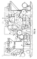
- Fig. 1A shows the location of the crawling-drive roll 10 of the press felt H in the press section.
- the felt is operated by means of the drive roll 10, for example, to moisten the felt.
- the roll 10 is a so-called crawling-drive roll.
- the felt is operated by means of the nip N, and in such a situation the roll 10 is in a position of free rotation.
- Fig. 1B shows the crawling-drive device of the press felt as viewed in the machine direction.
- the press felt H is operated by the press-felt drive roll 10, whose axles 10a are mounted in bearings 11.
- the drive roll 10 receives its rotation drive directly from the drive rim 20, whose body 20a is connected to the roll 10 axle 10a.
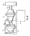
- Fig. 2 shows a first preferred embodiment of the crawling-drive device in accordance with the invention.
- the drive shaft 15 of the hydraulic motor 14 is connected with a drive wheel 19.
- the hydraulic motor 14 is provided with an input connection 18a and an output connection 18b for fluid.
- the hydraulic motor 14 is displaced by means of a cylinder device 17, preferably by means of a hydraulic cylinder.
- the drive wheel 19, preferably a cogwheel, placed on the output shaft 15 of the hydraulic motor 14 is brought into engagement with the drive rim 20, preferably a toothed rim.
- the spring 23 between the piston 21 of the hydraulic cylinder 17 and the cylinder end 22 shifts the drive wheel 19 out of contact with the drive rim 20.
- the arrangement operates both as a drive gear for the roll 10 and as an overrunning clutch.
- the spring 23 shifts the drive wheel 19 out of contact with the drive rim 20, in which case the drive roll 10 is in the position of free rotation.
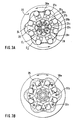
- FIG 3A shows a second preferred embodiment of the crawling-drive device.
- the drive rim 20 comprises a wave-shaped inside rim form 24.
- the rotation of the drive rim 20 is produced by passing pressurized fluid through the inlet opening to the distributor 28 and from the distributor 28 further into the cylinders 29a,29b... .
- Some of the drive pistons 26a,26b... are in the work stage and push the cam-wheels 27a,27b... against the drive rim 20.
- the distributor 28 which revolves synchronously with the drive rim 20, closes the inlet of fluid into the piston 26 that has completed its work stage and opens the exhaust opening to the fluid space of said piston. In a corresponding way, the distributor 28 opens the flow passage for the pressurized fluid into the piston 26 that is in the bottom position in its cylinder.
- the springs 30a,30b... press the pistons 26a,26b... into their bottom positions in the cylinders 29a,29b... and keep the cam-wheels 27a,27b... placed at the ends of the pistons 26a,26b... apart from the drive rim 20.
- the drive rim 20 can be rotated freely so that the system does not cause an operating resistance to the movement of rotation.
- the cam mechanism permits a drive system in which the drive device and the disengaging coupling constitute a single unit.
Landscapes
- Engineering & Computer Science (AREA)
- Mechanical Engineering (AREA)
- Paper (AREA)
- Nitrogen Condensed Heterocyclic Rings (AREA)
Applications Claiming Priority (2)
| Application Number | Priority Date | Filing Date | Title |
|---|---|---|---|
| FI920746 | 1992-02-20 | ||
| FI920746A FI89391C (fi) | 1992-02-20 | 1992-02-20 | Foerfarande och anlaeggning vid krypdrift av pressfilt i pappersmaskin |
Publications (2)
| Publication Number | Publication Date |
|---|---|
| EP0557263A1 true EP0557263A1 (fr) | 1993-08-25 |
| EP0557263B1 EP0557263B1 (fr) | 1997-10-29 |
Family
ID=8534762
Family Applications (1)
| Application Number | Title | Priority Date | Filing Date |
|---|---|---|---|
| EP93850034A Expired - Lifetime EP0557263B1 (fr) | 1992-02-20 | 1993-02-19 | Dispositif pour le conditionnement d'un nouveau feutre de presse dans une machine à papier |
Country Status (6)
| Country | Link |
|---|---|
| US (1) | US5326435A (fr) |
| EP (1) | EP0557263B1 (fr) |
| AT (1) | ATE159780T1 (fr) |
| CA (1) | CA2090070C (fr) |
| DE (1) | DE69314822T2 (fr) |
| FI (1) | FI89391C (fr) |
Citations (3)
| Publication number | Priority date | Publication date | Assignee | Title |
|---|---|---|---|---|
| DE3506155A1 (de) * | 1985-02-22 | 1986-06-05 | Daimler-Benz Ag, 7000 Stuttgart | Antriebsanordnung fuer fahrzeuge, insbesondere personenkraftwagen |
| DE4004726A1 (de) * | 1989-02-16 | 1990-08-23 | Valmet Oy | Antriebseinheit eines rollapparates einer papiermaschine oder papiernachbehandlungsmaschine und dessen hydraulikantriebssystem |
| DE9109312U1 (fr) * | 1991-07-27 | 1991-09-26 | J.M. Voith Gmbh, 7920 Heidenheim, De |
Family Cites Families (1)
| Publication number | Priority date | Publication date | Assignee | Title |
|---|---|---|---|---|
| FI810575L (fi) * | 1981-02-25 | 1982-08-26 | Valmet Oy | Foerfarande och anordning foer byte av en pick-up-vaevnad och/eller en pressvaevnad i presspartiet i en pappersmaskin |
-
1992
- 1992-02-20 FI FI920746A patent/FI89391C/fi active
-
1993
- 1993-02-19 US US08/020,139 patent/US5326435A/en not_active Expired - Lifetime
- 1993-02-19 DE DE69314822T patent/DE69314822T2/de not_active Expired - Fee Related
- 1993-02-19 EP EP93850034A patent/EP0557263B1/fr not_active Expired - Lifetime
- 1993-02-19 AT AT93850034T patent/ATE159780T1/de not_active IP Right Cessation
- 1993-02-22 CA CA002090070A patent/CA2090070C/fr not_active Expired - Fee Related
Patent Citations (3)
| Publication number | Priority date | Publication date | Assignee | Title |
|---|---|---|---|---|
| DE3506155A1 (de) * | 1985-02-22 | 1986-06-05 | Daimler-Benz Ag, 7000 Stuttgart | Antriebsanordnung fuer fahrzeuge, insbesondere personenkraftwagen |
| DE4004726A1 (de) * | 1989-02-16 | 1990-08-23 | Valmet Oy | Antriebseinheit eines rollapparates einer papiermaschine oder papiernachbehandlungsmaschine und dessen hydraulikantriebssystem |
| DE9109312U1 (fr) * | 1991-07-27 | 1991-09-26 | J.M. Voith Gmbh, 7920 Heidenheim, De |
Also Published As
| Publication number | Publication date |
|---|---|
| US5326435A (en) | 1994-07-05 |
| FI920746A0 (fi) | 1992-02-20 |
| FI89391B (fi) | 1993-06-15 |
| FI89391C (fi) | 1993-09-27 |
| DE69314822D1 (de) | 1997-12-04 |
| EP0557263B1 (fr) | 1997-10-29 |
| CA2090070A1 (fr) | 1993-08-21 |
| CA2090070C (fr) | 1997-10-21 |
| ATE159780T1 (de) | 1997-11-15 |
| DE69314822T2 (de) | 1998-03-26 |
Similar Documents
| Publication | Publication Date | Title |
|---|---|---|
| GB2115512A (en) | Wet-type clutch/brake device mounted in a flywheel | |
| FI81321B (fi) | Drivenhet foer pappersmaskin eller foer en efterbehandlingsmaskin foer papper och ett hydrauldrivsystem foer denna. | |
| JPS5449433A (en) | Hydraulic motor unit for driving crawler | |
| KR100465422B1 (ko) | 무한궤도차량용차륜구동장치 | |
| GB1577432A (en) | Press drive mechanisms | |
| EP1084832A1 (fr) | Procédé et dispositif pour imprimer des bandes avec des images de grande longueur | |
| US4458794A (en) | Drive system with oil shear clutch-brake unit | |
| EP0557263A1 (fr) | Procédé et dispositif pour le conditionnement d'un feutre de presse dans une machine à papier | |
| EP0046752A1 (fr) | Entrainement a engrenage a freinage rapide-lent. | |
| EP0328741B1 (fr) | Dispositif d'entraînement par à-coups | |
| PL82441B1 (fr) | ||
| US4295423A (en) | Liquid distributing roller assembly for printing machines | |
| JPH0359796B2 (fr) | ||
| JPS56101436A (en) | Brake device | |
| US20040074406A1 (en) | Drive mechanish of a printing unit | |
| EP0124592A1 (fr) | Dispositif de couple hydraulique | |
| GB2047360A (en) | Vehicle transmission with means for braking the gearbox | |
| GB1594972A (en) | Planetary gear including a brake device | |
| US1738308A (en) | Brake apparatus | |
| NO893258L (no) | Kopling for kraftuttaksaksling. | |
| GB2266270A (en) | Ductor roller drive for a printing press. | |
| JPH0361559B2 (fr) | ||
| JPS62238744A (ja) | 胴にエネルギ−を供給する装置 | |
| JP3284752B2 (ja) | 微速機構付ホイスト | |
| JP2745274B2 (ja) | 多板ディスクブレーキ装置 |
Legal Events
| Date | Code | Title | Description |
|---|---|---|---|
| PUAI | Public reference made under article 153(3) epc to a published international application that has entered the european phase |
Free format text: ORIGINAL CODE: 0009012 |
|
| AK | Designated contracting states |
Kind code of ref document: A1 Designated state(s): AT DE FR GB IT SE |
|
| 17P | Request for examination filed |
Effective date: 19930917 |
|
| 17Q | First examination report despatched |
Effective date: 19951103 |
|
| RAP1 | Party data changed (applicant data changed or rights of an application transferred) |
Owner name: VALMET CORPORATION |
|
| GRAG | Despatch of communication of intention to grant |
Free format text: ORIGINAL CODE: EPIDOS AGRA |
|
| GRAH | Despatch of communication of intention to grant a patent |
Free format text: ORIGINAL CODE: EPIDOS IGRA |
|
| GRAH | Despatch of communication of intention to grant a patent |
Free format text: ORIGINAL CODE: EPIDOS IGRA |
|
| GRAA | (expected) grant |
Free format text: ORIGINAL CODE: 0009210 |
|
| AK | Designated contracting states |
Kind code of ref document: B1 Designated state(s): AT DE FR GB IT SE |
|
| PG25 | Lapsed in a contracting state [announced via postgrant information from national office to epo] |
Ref country code: FR Free format text: LAPSE BECAUSE OF FAILURE TO SUBMIT A TRANSLATION OF THE DESCRIPTION OR TO PAY THE FEE WITHIN THE PRESCRIBED TIME-LIMIT Effective date: 19971029 |
|
| REF | Corresponds to: |
Ref document number: 159780 Country of ref document: AT Date of ref document: 19971115 Kind code of ref document: T |
|
| REF | Corresponds to: |
Ref document number: 69314822 Country of ref document: DE Date of ref document: 19971204 |
|
| ITF | It: translation for a ep patent filed |
Owner name: STUDIO CONS. BREVETTUALE S.R.L. |
|
| EN | Fr: translation not filed | ||
| PLBE | No opposition filed within time limit |
Free format text: ORIGINAL CODE: 0009261 |
|
| STAA | Information on the status of an ep patent application or granted ep patent |
Free format text: STATUS: NO OPPOSITION FILED WITHIN TIME LIMIT |
|
| 26N | No opposition filed | ||
| REG | Reference to a national code |
Ref country code: GB Ref legal event code: IF02 |
|
| PGFP | Annual fee paid to national office [announced via postgrant information from national office to epo] |
Ref country code: SE Payment date: 20080214 Year of fee payment: 16 Ref country code: IT Payment date: 20080220 Year of fee payment: 16 Ref country code: GB Payment date: 20080220 Year of fee payment: 16 Ref country code: DE Payment date: 20080219 Year of fee payment: 16 |
|
| PGFP | Annual fee paid to national office [announced via postgrant information from national office to epo] |
Ref country code: AT Payment date: 20080215 Year of fee payment: 16 |
|
| EUG | Se: european patent has lapsed | ||
| GBPC | Gb: european patent ceased through non-payment of renewal fee |
Effective date: 20090219 |
|
| PG25 | Lapsed in a contracting state [announced via postgrant information from national office to epo] |
Ref country code: AT Free format text: LAPSE BECAUSE OF NON-PAYMENT OF DUE FEES Effective date: 20090219 |
|
| PG25 | Lapsed in a contracting state [announced via postgrant information from national office to epo] |
Ref country code: DE Free format text: LAPSE BECAUSE OF NON-PAYMENT OF DUE FEES Effective date: 20090901 |
|
| PG25 | Lapsed in a contracting state [announced via postgrant information from national office to epo] |
Ref country code: GB Free format text: LAPSE BECAUSE OF NON-PAYMENT OF DUE FEES Effective date: 20090219 |
|
| PG25 | Lapsed in a contracting state [announced via postgrant information from national office to epo] |
Ref country code: IT Free format text: LAPSE BECAUSE OF NON-PAYMENT OF DUE FEES Effective date: 20090219 |
|
| PG25 | Lapsed in a contracting state [announced via postgrant information from national office to epo] |
Ref country code: SE Free format text: LAPSE BECAUSE OF NON-PAYMENT OF DUE FEES Effective date: 20090220 |