EP0552673B1 - Boîte de vitesse pour véhicule à moteur - Google Patents
Boîte de vitesse pour véhicule à moteur Download PDFInfo
- Publication number
- EP0552673B1 EP0552673B1 EP93100515A EP93100515A EP0552673B1 EP 0552673 B1 EP0552673 B1 EP 0552673B1 EP 93100515 A EP93100515 A EP 93100515A EP 93100515 A EP93100515 A EP 93100515A EP 0552673 B1 EP0552673 B1 EP 0552673B1
- Authority
- EP
- European Patent Office
- Prior art keywords
- shaft
- transmission
- gear
- housing
- module
- Prior art date
- Legal status (The legal status is an assumption and is not a legal conclusion. Google has not performed a legal analysis and makes no representation as to the accuracy of the status listed.)
- Expired - Lifetime
Links
Images

Classifications
-
- F—MECHANICAL ENGINEERING; LIGHTING; HEATING; WEAPONS; BLASTING
- F16—ENGINEERING ELEMENTS AND UNITS; GENERAL MEASURES FOR PRODUCING AND MAINTAINING EFFECTIVE FUNCTIONING OF MACHINES OR INSTALLATIONS; THERMAL INSULATION IN GENERAL
- F16H—GEARING
- F16H3/00—Toothed gearings for conveying rotary motion with variable gear ratio or for reversing rotary motion
- F16H3/02—Toothed gearings for conveying rotary motion with variable gear ratio or for reversing rotary motion without gears having orbital motion
- F16H3/08—Toothed gearings for conveying rotary motion with variable gear ratio or for reversing rotary motion without gears having orbital motion exclusively or essentially with continuously meshing gears, that can be disengaged from their shafts
- F16H3/087—Toothed gearings for conveying rotary motion with variable gear ratio or for reversing rotary motion without gears having orbital motion exclusively or essentially with continuously meshing gears, that can be disengaged from their shafts characterised by the disposition of the gears
- F16H3/093—Toothed gearings for conveying rotary motion with variable gear ratio or for reversing rotary motion without gears having orbital motion exclusively or essentially with continuously meshing gears, that can be disengaged from their shafts characterised by the disposition of the gears with two or more countershafts
-
- F—MECHANICAL ENGINEERING; LIGHTING; HEATING; WEAPONS; BLASTING
- F16—ENGINEERING ELEMENTS AND UNITS; GENERAL MEASURES FOR PRODUCING AND MAINTAINING EFFECTIVE FUNCTIONING OF MACHINES OR INSTALLATIONS; THERMAL INSULATION IN GENERAL
- F16H—GEARING
- F16H37/00—Combinations of mechanical gearings, not provided for in groups F16H1/00 - F16H35/00
- F16H37/02—Combinations of mechanical gearings, not provided for in groups F16H1/00 - F16H35/00 comprising essentially only toothed or friction gearings
- F16H37/04—Combinations of toothed gearings only
- F16H37/042—Combinations of toothed gearings only change gear transmissions in group arrangement
- F16H37/043—Combinations of toothed gearings only change gear transmissions in group arrangement without gears having orbital motion
-
- F—MECHANICAL ENGINEERING; LIGHTING; HEATING; WEAPONS; BLASTING
- F16—ENGINEERING ELEMENTS AND UNITS; GENERAL MEASURES FOR PRODUCING AND MAINTAINING EFFECTIVE FUNCTIONING OF MACHINES OR INSTALLATIONS; THERMAL INSULATION IN GENERAL
- F16H—GEARING
- F16H2200/00—Transmissions for multiple ratios
- F16H2200/0026—Transmissions for multiple ratios comprising at least one creep low gear, e.g. additional gear for extra low speed or creeping
-
- F—MECHANICAL ENGINEERING; LIGHTING; HEATING; WEAPONS; BLASTING
- F16—ENGINEERING ELEMENTS AND UNITS; GENERAL MEASURES FOR PRODUCING AND MAINTAINING EFFECTIVE FUNCTIONING OF MACHINES OR INSTALLATIONS; THERMAL INSULATION IN GENERAL
- F16H—GEARING
- F16H2200/00—Transmissions for multiple ratios
- F16H2200/003—Transmissions for multiple ratios characterised by the number of forward speeds
- F16H2200/0065—Transmissions for multiple ratios characterised by the number of forward speeds the gear ratios comprising nine forward speeds
-
- Y—GENERAL TAGGING OF NEW TECHNOLOGICAL DEVELOPMENTS; GENERAL TAGGING OF CROSS-SECTIONAL TECHNOLOGIES SPANNING OVER SEVERAL SECTIONS OF THE IPC; TECHNICAL SUBJECTS COVERED BY FORMER USPC CROSS-REFERENCE ART COLLECTIONS [XRACs] AND DIGESTS
- Y10—TECHNICAL SUBJECTS COVERED BY FORMER USPC
- Y10T—TECHNICAL SUBJECTS COVERED BY FORMER US CLASSIFICATION
- Y10T74/00—Machine element or mechanism
- Y10T74/19—Gearing
- Y10T74/19219—Interchangeably locked
- Y10T74/19223—Disconnectable counter shaft
-
- Y—GENERAL TAGGING OF NEW TECHNOLOGICAL DEVELOPMENTS; GENERAL TAGGING OF CROSS-SECTIONAL TECHNOLOGIES SPANNING OVER SEVERAL SECTIONS OF THE IPC; TECHNICAL SUBJECTS COVERED BY FORMER USPC CROSS-REFERENCE ART COLLECTIONS [XRACs] AND DIGESTS
- Y10—TECHNICAL SUBJECTS COVERED BY FORMER USPC
- Y10T—TECHNICAL SUBJECTS COVERED BY FORMER US CLASSIFICATION
- Y10T74/00—Machine element or mechanism
- Y10T74/19—Gearing
- Y10T74/19219—Interchangeably locked
- Y10T74/19233—Plurality of counter shafts
-
- Y—GENERAL TAGGING OF NEW TECHNOLOGICAL DEVELOPMENTS; GENERAL TAGGING OF CROSS-SECTIONAL TECHNOLOGIES SPANNING OVER SEVERAL SECTIONS OF THE IPC; TECHNICAL SUBJECTS COVERED BY FORMER USPC CROSS-REFERENCE ART COLLECTIONS [XRACs] AND DIGESTS
- Y10—TECHNICAL SUBJECTS COVERED BY FORMER USPC
- Y10T—TECHNICAL SUBJECTS COVERED BY FORMER US CLASSIFICATION
- Y10T74/00—Machine element or mechanism
- Y10T74/21—Elements
- Y10T74/2186—Gear casings
Definitions
- the invention relates to a transmission for motor vehicles, in particular for agricultural or commercial vehicles, which contains a plurality of transmission units which can optionally be assembled in a modular manner and form a multi-speed transmission.
- Gearboxes with a large number of gears are generally used in work vehicles, such as land and commercial vehicles.
- the actual and the required number of transmission ratios varies from application to application.
- the object on which the invention is based is seen in specifying a modular motor vehicle transmission which has the simple structure of a large number of different ones Allows gear structures from multiple gear units.
- Possible gear units are, for example, a gear shift module, one or more group shift modules, a creeper gear module, a front wheel drive gear module and a powershift gear module. These can optionally be assembled in different combinations in order to obtain different transmission conditions for different applications.
- the overall transmission composed of the transmission units can be inserted, for example, between the drive machine and the axle differential of the vehicle.
- Individual gear units are essentially hat-shaped. They have a bottom flange on one side of the housing, which is followed by a more or less closed side wall, through which the gear teeth are protected and which catches the gear oil.
- At least one gear unit contains one or more gear shafts, which are mounted on one end in the bottom flange of the associated gear housing and on the other end extend freely into the housing opening of the gear housing. The arrangement and mounting of the gear shafts is carried out in such a way that a preassembled gear unit results from the gear housing, the associated gear shafts and possibly other components.
- each shaft or each shaft section is assigned only to a hat-shaped (or pot-shaped) transmission housing, permits the complete preassembly of the shafts with the associated gear wheels, couplings, bearings, seals and the like outside the transmission housing.
- the necessary axial play of the ratchet wheels e.g. synchronous wheels
- the gear housing is then completed with the circuit for switching units (e.g. synchronizing units) and is finally available for assembly with another pre-assembled gear unit.
- the shaft ends protruding in the direction of or through the housing opening are inserted into bearing points which are embedded in the adjacent gear housing from the outside of the base flange.
- the shaft end which extends freely into the transmission housing opening, can be supported directly via a bearing in the bottom flange of the adjacent transmission unit.
- two adjacent gear units are arranged so that at least two of their shafts are aligned with one another.
- the bottom flange separating the two gear units has an opening through which one of the shafts extends and in which this shaft is mounted.
- the free end of this wave carries a concentric bearing that serves to accommodate the shaft end of the other shaft.
- the bearing point can either contain a spline through which a positive connection between the shafts can be produced, or it can be designed as a rotary bearing, for example as a needle bearing, which allows the shafts to be rotated relative to one another.
- a coupling is preferably provided, by means of which the two shafts can optionally be connected to one another in a rotationally fixed manner, whereby an additional gear can be realized in many cases.
- one of the hat-shaped gear units is a gear shift transmission module, in the bottom flange of which an input shaft with at least two idler gears that can be engaged by shifting units and a fixed gear shaft with at least two fixed gears meshing with the idler gears are mounted.
- the fixed gear shaft carries a further fixed gear in the region of its second, free end, which meshes with an input gear of an adjacent gear unit.
- an adjacent transmission unit e.g. a group transmission transmission module
- the second ends of the input shaft and the fixed gear shaft are supported on the base flange or a suitable receptacle of the adjacent transmission unit.
- the free end of the input shaft of the gear shift transmission module is expediently rotatably mounted in a recess in the shaft end of a shaft of the adjacent transmission unit. Furthermore, both shafts can be connected to one another in a rotationally fixed manner by means of an engaging gear teeth. With such a gear shift module, 3 forward gears can be realized. The usual idler gear for third gear can be saved here because the further fixed gear of the fixed gear shaft meshes directly with an input gear arranged on the gear shaft of the adjacent gear unit.
- a preferred embodiment of the gearshift transmission module provides that the input shaft carries a third idler gear which can be engaged by a shift unit and the fixed gear shaft carries a third fixed gear and that the third idler gear and the third fixed gear engage with one another via a reversing gear which is rotatably mounted in the gearshift transmission housing. This creates a reverse gear.
- the gearshift transmission module is preferably arranged at the beginning of the transmission train, so that the switching point for the reverse gear is at the beginning of the transmission train.
- the switching work e.g. synchronous work
- the switching work when switching from reverse to the first forward gear or vice versa can be kept very low, since only the inertial masses of the clutch hub with the associated plates and the input shaft of the gear shift transmission module have to be mastered. This enables the direction of travel to be switched over quickly while the vehicle is still rolling without the switch point actuated during the switchover being subjected to excessive stress.
- one of the hat-shaped gear units is a group manual transmission module, in the bottom flange of which at least one fixed gear shaft and at least one idler gear shaft are mounted, which carry mutually associated pairs of fixed gears and idler gears, the idler gears being rotatably connected to the idler gear shaft by switching units.
- Another hat-shaped gear unit is preferably designed as an intermediate gearbox module, which can be inserted, for example, between a gearshift gearbox module and a group gearbox module.
- the intermediate transmission is, for example, a further group transmission, by means of which the number of switchable groups can be increased.
- a fixed gear shaft and an idler gear shaft are also arranged in the intermediate gearbox housing. which carry associated pairs of fixed gears and idler gears, the idler gears being rotatably connected to the idler gear shaft by switching units. Both shafts are mounted with their first end in the bottom flange of the intermediate gearbox housing and extend freely with their second end into the opening of the intermediate gearbox housing opposite the bottom flange.
- the fixed gear shaft serves as the input shaft of the intermediate gear module and is expediently non-rotatably connected to the fixed gear shaft of the downstream group gear module.
- the idler gear shaft is preferably rotatably connected to the idler gear shaft of the subordinate group transmission module.
- the shafts can be connected by coupling teeth. (Fig. 2).
- the fixed gear shaft and on the other hand the idler gears of the idler gear shaft can be easily replaced by another fixed gear shaft or other idler gears.
- the group gearbox, the position of the switching devices and the adjacent gearbox need not be changed. Group transmissions with different transmission ratios can therefore be manufactured inexpensively using largely the same components.
- a selected fixed gear shaft and an idler gear shaft that is the same for all applications can be used in the bearing positions of the gear housing that adjoins the open side of the group transmission module, e.g. B. the differential gear housing.
- the idler gears and shift units are selected and mounted on the idler gear shaft.
- the hat-shaped group gearbox is slipped over the shafts, so that the first ends of the shafts of bearings in the bottom flange of the group transmission housing are received.
- the flange located on the open side of the group transmission housing is attached to the differential gear housing.
- the open side of the gear shift housing preferably adjoins the outside of the base flange of the group shift transmission case. Furthermore, a fixed gear of the fixed gear shaft of the gear shift transmission module meshes with a fixed gear of the fixed gear shaft of the group shift gear module. As already mentioned, this enables a gearwheel for the third gear to be saved.
- the fixed gear shaft of the group transmission module expediently protrudes through an opening in the bottom flange of the group transmission module.
- a further embodiment of the invention provides that a fixed gear of the fixed gear shaft of the group transmission module (or of the intermediate gear module) serves as an input gear and meshes on the one hand with the further fixed gear of the fixed gear shaft of the gear shift module and on the other hand with an idler gear of the idler gear shaft of the group transmission module.
- the input gear thus fulfills two tasks: firstly, it is an effective component of the gearshift transmission module, in which it absorbs the power flow from the fixed gear shaft of the gearshift transmission module, and secondly, it is part of the group manual transmission module and operates an idler gear that can be switched by a switching point. Compared to a conventional gearbox, a gearwheel can thus be omitted.
- an idler gear mounted on an idler gear shaft which meshes with the gear of a fixed gear gear shaft, can be exchanged for another idler gear that has the same diameter, however has a different number of teeth.
- This solution makes it possible, for example in the case of transmissions according to FIG. 3 or 4, for groups E and D to have different transmission ratios with the same center distance, although the gears G5F and G3D are identical in their tooth geometry. Therefore, the group transmission module can be flanged to the gear transmission module directly instead of the intermediate transmission module without changing the wheels.
- a different number of teeth can be achieved by the principle of the profile shift, which makes it possible to increase or decrease the number of teeth of a gear meshing with the same basic gear within certain limits compared to an optimal number of teeth .
- two different gearwheels the number of teeth of which differ by, for example, 3 to 4 teeth, can mesh with a base gearwheel.
- Another hat-shaped gear unit is preferably designed as a creeper gearbox module, which can be inserted, for example, between the gearbox gearbox and the group gearbox.
- a creeper input shaft and a secondary shaft Arranged in the creeper gearbox are a creeper input shaft and a secondary shaft, each of which is mounted with its first end in the bottom flange of the creeper gear module and with its second end extends freely into the opening of the creeper gearbox housing opposite the bottom flange.
- the fixed gear arranged on the creeper input shaft meshes with a relatively large fixed gear of the auxiliary shaft, and a relatively small fixed gear of the auxiliary shaft meshes with an idler gear mounted concentrically to the creeper input shaft.
- the creeper input shaft or the idler gear can be rotated with the Bring the fixed gear shaft of the subordinate group transmission module into engagement (Fig. 3).
- the second end of the creeper input shaft is rotatably mounted in a recess of the fixed gear shaft of the downstream group transmission module.
- a switching device for example a gearshift sleeve, is arranged on a shaft section that is non-rotatably connected to the fixed gear shaft of a downstream group shift transmission module and that optionally couples the fixed gear shaft of the group shift transmission module with a clutch body or the idler gear arranged on the creeper input shaft in a rotationally fixed manner.
- An embodiment of the invention which enables a very compact design, provides that in the region of the free second end of the creeper input shaft, a hollow shaft section which is concentric with this shaft is rotatably mounted and can be connected in a rotationally fixed manner to the fixed wheel shaft of the subordinate group transmission module via spline teeth.
- the hollow shaft section carries a non-rotatable gear in its central area, a toothing in the area of one of its ends, which meshes with an axially displaceable switching device (gearshift sleeve), and a rotatable idler gear in the area of its other end, which meshes with a fixed gear of the auxiliary shaft .
- At least one switching pin is connected to the switching device, which extends through a recess in the non-rotatable gear and can optionally be inserted into a recess of the rotatable idler gear by displacing the switching device, so that the idler gear is fixed relative to the fixed gear shaft of the group transmission module.
- This configuration is particularly advantageous, because to achieve the same function without the aid of the switching pin circuit To realize this would require additional space, additional intermediate gears and an additional switching point.
- the pin circuit therefore enables a very compact design.
- the switching device can preferably be used to connect a non-rotatable switching toothing of the creeper input shaft to the fixed gear shaft of the downstream group transmission module.
- the switching device either the creeper input shaft can be connected directly to the hollow shaft and thus to the fixed gear shaft of the downstream group transmission module (creeper gear module is ineffective), or with the switching device, the switching pins can be inserted into the recesses of the idler gear, thereby the idler gear is fixed on the hollow shaft (creeper is switched on).
- the creeper input shaft can also carry a further fixed gear, which serves as an input gear and meshes with the further fixed gear of the fixed gear shaft of the gearshift transmission module.
- the input gear fulfills the tasks already described.
- an idler gear shaft is provided in the creeper gear module, the two idler gears of which can be switched by a switching device mesh with the input gear of the creeper input shaft or the non-rotatable gear of the hollow shaft (Fig. 4).
- the idler gear shaft of the creeper gearbox module and the idler gear shaft of a group gearbox module arranged downstream of the creeper gearbox module are preferably connected to one another in a rotationally fixed manner.
- the idler gear which is mounted on the idler gear shaft of the creeper gear module and meshes with the input gear of the crawler gear module
- the idler gear which is mounted on the idler gear shaft of a group gear module subordinate to the crawler gear module, and the gearbox gearbox of the fixed gear gearbox with the group that can be used as an input gear combs, gears with the same diameter but different numbers of teeth.
- a transmission unit is designed as a front-wheel drive transmission module, the front-drive transmission housing of which can be fastened at the bottom of the group transmission transmission housing to the jacket area thereof, an input toothing of the front-wheel drive transmission module being connected to a toothing fixed on the idler gear shaft of the group transmission transmission module.
- An output shaft is expediently mounted in the front-wheel drive gear housing and can be coupled by means of a clutch to an idler gear mounted on the output shaft.
- a gear wheel with two toothings is rotatably mounted on a secondary shaft mounted in the front wheel drive gearbox housing, the first toothing of which is an input toothing of the front wheel drive gearbox module and the second toothing meshes with the idler gear.
- This design allows a very simple change in the gear ratio, which is required, for example, when replacing the front wheels of the vehicle with front wheels with a different diameter.
- a gearwheel which is suitable as a drive gearwheel for a front-wheel drive gearbox module, is fixed on the idler gear shaft of the group transmission module.
- the gearwheel is preferably used at the same time to engage a parking lock.
- the parking lock can thus block the drive to the rear wheels of the vehicle. If the front wheel drive is switched on, the parking lock acts on both the front and rear wheels.
- a countershaft is provided with a countershaft housing that can be fastened within the group transmission gearbox.
- the countershaft housing can be fastened to the outer side of the differential housing and protrude into the group transmission housing.
- Two axles for rotatably accommodating gearwheels are arranged in the countershaft housing.
- An input toothing of the countershaft meshes with a fixed gear of the fixed gear shaft of the group transmission module.
- an output toothing of the countershaft meshes with an idler gear of the idler gear shaft of the group transmission module.
- the two shafts of the countershaft each have a gearwheel with two toothings, one toothing of the two gearwheels meshing with one another and the other two toothingwheels of the gearwheels form the input toothing and the output toothing.
- the gear makes it possible to adapt a group (group A in the exemplary embodiment described) to special customer requirements.
- a transmission can provide a relatively slow group.
- Such slow groups are required, for example, when planting.
- the adjustment only requires the attachment or replacement of the countershaft and possibly the input and / or output gear. Since this is a simple component and for the economical production does not require large production series, individual customer requests can also be fulfilled.
- a powershift transmission module can be used instead of the gearshift transmission module, the housing of which can be fastened to the transmission housing of the subsequent transmission unit and the output shaft of which can be connected in a rotationally fixed manner to the input shaft of the subsequent transmission unit.
- the powershift transmission module preferably has a reversing device.
- the second letter of the reference symbol for a clutch following the first letter C indicates the gear or range which can be engaged or disengaged by the clutch.
- the terms "right”, “top” and the like in the following only refer to how the components are shown in the drawing. This information should not be regarded as a restriction with regard to the spatial position of the components of an actual transmission arrangement.
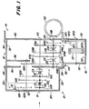
- the gear shift transmission module 10 is essentially hat-shaped, ie it has a base flange 20 and lateral surfaces 22 and is open on the side opposite the base flange 20 .
- a suitable flange 24 is preferably provided in the region of the open side, through which the gear shift transmission module 10 can be fastened to an adjacent transmission module.
- the adjacent transmission module can, for example, as shown in FIG. 1, be a group transmission module 12.
- the group transmission module 12 is likewise hat-shaped in a similar manner and contains a bottom flange 30, lateral surfaces 32 and a flange 34. Furthermore, the group transmission module 12 preferably contains an inner wall 36 which is designed as a shaft support structure, which will be discussed in more detail below.
- the differential housing 14 can have any suitable shape, provided that it has a base area 40, through which it covers the open side of the group transmission module 12. If for some reason the group transmission module 12 is not to be arranged directly on the differential housing 14, but rather is to be arranged at a distance from it, this requirement can also be dispensed with by the open side of the group transmission module 12 not being closed by the base 40, but by another plate .
- the front-wheel drive transmission module 16 is also hat-shaped and contains a bottom flange 50, lateral surfaces 52 and a flange 54, with which it can be fastened via an opening in the lateral surface 32 of the group transmission module 12.
- the open side of the front-wheel drive transmission module 16 is closed by the outer surface 32 of the group transmission transmission module 12.
- the bottom flanges 20, 30, 40 and the outer surfaces 32, 52 of the transmission modules 10, 12 , 14, 16 suitable passages. If certain shafts or passages are not required for a specific application, the passages can be closed by corresponding covers, not shown. For example, if front wheel drive is not required, the front wheel drive transmission module can 16 omitted and a cover can be screwed over the opening in the lateral surface 32 of the group transmission module 12.
- a shaft S1 is rotatably arranged in the gearshift transmission module 10 and is aligned with a shaft S3, which is located within the group shift transmission module 12.
- the right end of the shaft S3 is rotatably supported in the bottom flange 40 of the differential case 14.
- the left end of the shaft S3 is rotatably supported in the bottom flange 30 of the group transmission module 12.
- the left end of the shaft S1 is rotatably supported in the bottom flange 20 of the gear transmission module 10, and its right end is rotatably supported within a recess in the left end of the shaft S3.
- the gears G1R, G11, G12 are rotatably mounted on the shaft S1. Clutches CR, C1, C2, C3 are also arranged on shaft S1.
- the gears G1R, G11, G12 can be connected non-rotatably to the shaft S1 by means of the couplings CR, C1, C2, and the shafts S1 and S3 can optionally be non-rotatably connected to one another by the coupling C3.
- the left end of a shaft S2 is rotatably supported in the bottom flange 20 of the gear shift transmission module 10.
- the right end of the shaft S2 projects through an opening in the bottom flange 30 of the group transmission module 12 and is rotatably mounted in the inner wall 36 of the group transmission module 12.
- the gears G2R, G21, G22, G20 are arranged on the shaft S2 in a rotationally fixed manner.
- the gears G21 and G22 mesh with the gears G11 and G12.
- the gear wheel G20 of the shaft S2 is located within the group transmission module 12.
- the bottom flange 20 of the gearshift transmission module 10 carries an idler shaft SI, on which a reverse gear GIR is rotatably mounted, which constantly meshes with the gears G2R and G1R.
- the gears G3D, G3C, G3B, G3A are arranged on the shaft S3 in a rotationally fixed manner.
- the G3D gear constantly meshes with the G20 gear.
- the left end of a shaft S4 is in the bottom flange 30 of the group transmission module 12, and the right end of this shaft S4 is rotatably mounted in the bottom flange 40 of the differential case 14.
- the gears G4D, G4C, G4B, G4A are rotatably mounted on the shaft S4 within the group transmission module 12.
- the shaft S4 carries a non-rotatable gear G40 within the group transmission module 12 and a non-rotatable bevel gear GB within the differential housing 14.
- a differential gear GD is rotatably arranged, with which the bevel gear GB meshes continuously.
- the gears G4D, G4C, G4B, G4A can optionally be connected to the shaft S4 in a rotationally fixed manner by means of associated couplings SD, SS, SB, SA.
- a shaft SF1 is rotatably supported by a lateral surface 52 of the front wheel drive gear housing 16. On it a double gear is rotatably mounted, which has two gears GF1, GF2. The toothing GF1 constantly meshes with the gear wheel G40.
- a shaft SF2 is rotatably supported on two lateral surfaces 52 of the front wheel drive gear housing 16. It protrudes from the front wheel drive housing 16 with at least one end (not shown) to connect to the front wheel drive mechanism.
- the gear wheel GF3, which is in constant engagement with the toothing GF2, is rotatably arranged on the shaft SF2 and can optionally be connected in a rotationally fixed manner to the shaft SF2 by means of a coupling CF.
- the shaft S4 outputs the output power from the group transmission module 12 via the bevel gear GB to the differential gear GD. If a front wheel drive transmission module 16 (as shown) is installed, the output power can branch out and a part can be delivered to the front wheel drive transmission module 16 via the gear wheel G40. If the clutch CF is engaged, power is delivered to the front wheels, not shown. If a front wheel drive transmission module 16 is not provided, the gear wheel G40 can in principle also be omitted.
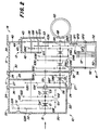
- the gear arrangement according to FIG. 2 contains two further gear modules. Between the gear shift module 10 and the group shift module 12, an intermediate shift module 11 is inserted, which is also essentially hat-shaped and contains a bottom flange 26, lateral surfaces 27 and a flange 28. As shown, the open side of the gear shift module 10 is essentially through the bottom flange 26 of the intermediate shift module 11 closed, while the bottom flange 30 of the group transmission module 12 essentially closes the open side of the intermediate transmission module 11.
- the intermediate transmission module 11 also has an intermediate wall 29 which is located essentially at a location corresponding to the inner wall 36 of the group transmission module 12 shown in FIG. 1.
- the inner wall 36 of the group transmission module 12 can be omitted in the exemplary embodiment according to FIG. 2 if this is considered to be expedient, but it can also be retained in order to enable a simple, later transmission conversion.
- the shafts S3 and S4 are rotatably mounted in the base flanges 30 and 40. 1, however, the left end of the shaft S3 received the shaft S1, it now carries the right end of a shaft S5 which extends in the intermediate gear module 11. 1, the shaft S1 is rotatably mounted in the shaft S3, according to FIG. 2 the shaft S5 is connected to the shaft S3 in a rotationally fixed manner via splines or the like. The left end of the shaft S5 is rotatably mounted in the bottom flange 26 of the intermediate gear module 11 and rotatably receives the right end of the shaft S1 in a bearing in essentially the same way as it is with reference to FIG.
- shaft C3 (and thus indirectly shaft S3) can also be connected in a rotationally fixed manner to shaft S1 by coupling C3.
- the S5 shaft rotatably supports the G5F and G5E gears.
- the G20 gear constantly meshes with the G3D gear.
- a shaft S6 is rotatably mounted in the bottom flanges 26 and 30 within the intermediate gear module 11. Your one end is over a spline or otherwise rotatably connected to the shaft S4.
- the gears G6F and G6E are rotatably mounted on the shaft S6 and constantly mesh with the gears G5F and G5E.
- the S6 shaft carries the CF and CE couplings, through which the gears G6F and G6E can optionally be connected to the S6 shaft in a rotationally fixed manner.
- the auxiliary transmission module 13 contains a bottom flange 42, a lateral surface 43 and a flange 44, through which the auxiliary transmission module 13 can be fastened to the bottom surface 40 of the differential housing 14.
- a corresponding cover plate 45 is fastened on the other side of the bottom surface 40 within the differential housing 14.
- a double gearwheel is rotatably mounted on shaft S7 and has two gears G71, G72.
- the G71 toothing constantly meshes with the G3A gear.
- a double gearwheel is also rotatably mounted on the shaft S8 and has two toothings G81, G82.
- the toothing G81 constantly meshes with the toothing G72, and the toothing G82 constantly meshes with the gear G4A.
- the gear ratio of the additional gear module 13 further reduces the reduction in area A. That in connection with the 18-speed transmission
- the additional transmission module 13 shown can, if desired, also be added to a 12-speed transmission.
- the gear arrangement of the additional transmission module 13 can be changed without difficulty and adapted to different requirements. By changing the double gears rotatably mounted on the shafts S7 and S8, large changes in the reduction ratios can easily be realized. Furthermore, the cover plate 45 can be omitted if other fastening options for the shafts S7 and S8 are provided.
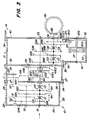
- FIG. 3 there is also an intermediate gear module 11 between the gear shift module 10 and the group gear module 12.
- a creeper gear was inserted instead of the additional range gears.
- the cross section through the transmission has been shown slightly modified, in that the shaft S2 is divided and shown with its right end, which projects into the intermediate transmission module 11, in the vicinity of the upper lateral surface 27.
- the outer gear structure essentially corresponds to that shown in FIG. 2.
- a creeper shaft SC is located at approximately the same location as the shaft S5 in the embodiment shown in FIG. 2, that is, the right end of the creeper shaft SC is carried by the shaft S3 and its left end is mounted in the bottom flange 26 and rotatably supports the shaft S1.
- the left end of the creeper shaft SC can be connected to shaft S1 in a rotationally fixed manner by means of a coupling C3.
- the right end of the creeper shaft SC is rotatably mounted in the shaft S3 and does not have a spline in connection with this.
- the gear wheels GC1 and GC2 are arranged on the creeper shaft SC in a rotationally fixed manner, the gear wheel GC1 constantly meshing with the gear wheel G20.
- the gear wheel G3C1 is arranged in a rotationally fixed manner on a section of the shaft S3 which projects into the intermediate gearbox module 11.
- Gear G3C2 is rotatably supported over the same portion of shaft S3.
- a shaft S9 is rotatably supported between the base flanges 26 and 30 and supports the two gears G91 and G92, which mesh constantly with the gears GC2 and G3C2.
- the creeper shaft SC carries the clutches CC1 and CC2. Through the clutch CC1, the shaft S3 can be connected in a rotationally fixed manner to the creeper shaft SC, so that the creeper is avoided.
- the clutch CC2 is preferably a shift pin clutch, by means of which the shaft S3 can optionally be connected in a rotationally fixed manner to the gear wheel G3C2 in order to switch on the creeper gear.
- FIG. 4 shows a transmission which contains all the modules described so far.
- This transmission structure is similar to that shown in FIG. 3, but additionally contains the shaft S6 with the associated gear wheels G6F, G6E and clutches CF, CE, which have been described with reference to FIG. 2.
- the gears G6F and G6E constantly mesh with the gears GC1 and G3C1 of the shaft SC and not, as shown in FIG. 3, with the gears G5F and G5E of the shaft S5.
- the gear modules described allow extremely high flexibility with regard to gear mounting, in which a large number of different gears with different requirements can be implemented by selection and simple assembly of the gear modules.
- the exact transmission ratio can be given for given transmission modules easily adapt individual groups or gears to requirements, whereby a basic gear of the translation can remain the same. This is achieved in that some of the gears are replaced by gears of the same diameter but with different numbers of teeth.
- the change in the gear ratio can be achieved by the principle of the profile shift.
- the modular gearbox consists of simple components that can be manufactured in large quantities and at reasonable prices.
Claims (30)
- Transmission pour véhicules automobiles, notamment pour véhicules agricoles ou utilitaires, qui comporte plusieurs unités de transmission, qui peuvent être réunies au choix de façon modulaire et forme une transmission à plusieurs vitesses,- que la transmission comporte au moins deux unités de transmission, dont les carters sont réalisés chacun essentiellement en forme de chapeau et contiennent, sur un côté du carter, un flasque de fond (20,26,30,42) et sur le côté opposé, une ouverture de carter, qui peut être fermée en direction de l'extérieur par le flasque de fond (26,30,40) d'un carter voisin de la transmission,- qu'à chacune des deux unités de la transmission est associé au moins un arbre (S1,S2,S3,S4,S5,S6,S7,S8,S9), qui est tourillonné, à une extrémité, dans le flasque de fond (20,26,30,42) du carter associé de la transmission et, à l'autre extrémité, s'étend librement dans l'ouverture du carter de la transmission,- que le carter de la transmission forme, avec l'arbre associé (S1,S2,S3,S4,S5,S6,S7,S8,S9) de la transmission ainsi que, éventuellement, avec d'autres composants, une unité de transmission pouvant être en soi préassemblée, et- que l'extrémité, qui s'étend librement dans l'ouverture du carter de la transmission, de l'arbre (S1,S2,S3, S4,S5,S6,S9) de la transmission prend appui sur le flasque de fond (26,30,40) ou sur un logement approprié (29,36) d'une unité de transmission voisine.
- Transmission selon la revendication 1, caractérisée en ce qu'un palier est formé entre l'extrémité, qui s'étend librement, de l'arbre (S1,S5,S6) de la transmission et l'extrémité voisine d'un arbre (S3,S5, S4) d'une unité de transmission voisine.
- Transmission selon la revendication 1 ou 2, caractérisée en ce que la première extrémité, qui est tourillonnée dans un flasque de fond (26,30) d'un arbre (S3, S4,S5,SC) d'une unité de transmission voisine possède un évidement, qui s'ouvre en direction du côté arrière du carter de l'unité de transmission voisine, et qui loge et soutient l'extrémité, qui s'étend librement, d'un arbre (S1,S5,S6) de la première unité de la transmission.
- Transmission selon l'une des revendications 1 à 3, caractérisée en ce- que l'une des unités de la transmission contient un module de transmission à changement de vitesses (10), comporte un carter de transmission à changement de vitesses réalisé en forme de chapeau de la transmission à changement de vitesses, qui loge un arbre d'entrée (S1) comportant au moins deux pignons fous (G11,G12), qui peuvent être enclenchés par des unités de commutation (C1,C2), ainsi qu'un arbre (S2) comportant au moins deux pignons fixes (G21,G22) qui engrènent avec les pignons fous (G11,G12),- que l'arbre d'entrée (S1) et l'arbre (S2) portant les pignons fixes sont montés, par une première de leurs extrémités, dans le flasque de fond (20) du carter de la transmission à changement de vitesses et s'étendent librement, par leur seconde extrémité libre respective, dans l'ouverture, située à l'opposé du flasque de fond (20), du carter de la transmission à changement de vitesses,- que l'arbre (S2) portant les pignons fixes porte, dans la zone de sa seconde extrémité libre, un autre pignon fixe (G20), qui engrène avec un pignon d'entrée (G3D, G5F, GC1) d'une unité de transmission voisine, et- qu'après le montage de la transmission, les secondes extrémités de l'arbre d'entrée (S1) ainsi que de l'arbre (S2) portant les pignons fixes prennent appui dans la zone du flasque de fond (26,30) ou d'un logement approprié (29,36) de l'unité de transmission voisine.
- Transmission selon la revendication 4, caractérisée en ce que l'extrémité libre de l'arbre d'entrée (S1) du module de transmission à changement de vitesses (10) est monté rotatif dans un évidement d'un arbre (S3,S5) de l'unité de transmission voisine, et que l'arbre (S3,S5) de l'unité de transmission voisine peut être relié avec blocage en rotation à une denture de commutation, au moyen de laquelle l'arbre d'entrée (S1) du module de transmission à changement de vitesses (10) peut être relié avec blocage en rotation à l'arbre (S3,S5) de l'unité de transmission voisine, par l'intermédiaire d'une unité de commutation (C3), qui est disposée sur l'arbre d'entrée (S1) du module de transmission à changement de vitesses (10).
- Transmission selon la revendication 4 ou 5, caractérisée en ce que l'arbre d'entrée (S1) du module de transmission à changement de vitesses (10) porte un troisième pignon fou (G1R), qui peut être enclenché au moyen d'une unité de commutation (C1), et l'arbre (S2) portant les pignons fixes porte un troisième pignon fixe (G2R), et que le troisième pignon fou (G1R) et le troisième pignon fixe (G2R) engrène réciproquement par l'intermédiaire d'un pignon inverseur (GIR) monté rotatif dans le carter de la transmission à changement de vitesses.
- Transmission selon l'une des revendications 4 à 6, caractérisée en ce que le module de transmission à changement de vitesses (10) est disposé au début de la chaîne de la transmission.
- Transmission selon l'une des revendications 1 à 7, caractérisée en ce- que l'autre des unités de transmission contient un module de transmission formant groupe-relais (11,12) comportant un carter de la transmission formant groupe-relais en forme de chapeau, qui loge un arbre (S3) portant des pignons fixes et un arbre (S4) portant des pignons fous, ces arbres portant des couples réciproquement associés formés de pignons fixes (G3D,G3C,G3D,G3A) et de pignons fous (G4D,G4c,G4b,G4A), les pignons fous (G4D,G4B,G4C, G4A) pouvant être reliés avec blocage en rotation à l'arbre (S4) portant les pignons fous, au moyen d'unités de commutation (CD,CC,CB,CA), et- que l'arbre (S3) portant les pignons fixes et l'arbre (S4) portant les pignons fous sont tourillonnés, par une première extrémité respective, dans le flasque de fond (30) du carter de la transmission formant groupe-relais.
- Transmission selon la revendication 8, caractérisée en ce que le carter de la transmission formant groupe-relais peut être fixé, par son extrémité ouverte, située à l'opposé du flasque de fond (30), sur un carter de différentiel (14), que les secondes extrémités de l'arbre (S3) portant les pignons fixes et de l'arbre (S4) portant les pignons fous sont tourillonnés dans le carter de différentiel (14) et que l'arbre (S4) portant les pignons fous porte avec blocage en rotation, au niveau de sa seconde extrémité, le pignon conique (GB) d'un différentiel.
- Transmission selon la revendication 8 ou 9, caractérisée en ce- qu'entre le carter de la transmission à changement de vitesses et le carter de la transmission formant groupe-relais d'une unité de transmission peut être insérée une unité de transmission, qui contient un module de transmission intermédiaire (11) comportant un carter en forme de chapeau,- que dans le carter de transmission intermédiaire sont disposés un arbre (S5) portant les pignons fixes et un arbre (S6) portant des pignons fous, ces arbres portant des couples respectivement associés de pignons fixes (G5F, G5E) et de pignons fous (G6F, G6E), les pignons fous (G6F, G6E) pouvant être reliés avec blocage en rotation à l'arbre (S6) portant les pignons fous, au moyen d'unités de commutation (CF,CE),- que l'arbre (S5) portant les pignons fixes et l'arbre (S6) portant les pignons fous sont tourillonnés par une première extrémité respective, dans le flasque de fond (26) du carter de la transmission intermédiaire et s'étendent librement, par leur autre extrémité respective, dans l'ouverture du carter de la transmission intermédiaire, qui est situé à l'opposé du flasque de fond (26),- que l'arbre (S5) portant les pignons fixes est utilisé comme arbre d'entrée du module de transmission intermédiaire (11) et est relié avec blocage en rotation à l'arbre (S3) portant les pignons fixes d'un module de transmission formant groupe-relais (12) situé en aval, et- que l'arbre (S6) portant les pignons fous est relié avec blocage en rotation à l'arbre (S4) portant les pignons fous du module de transmission formant groupe-relais (12) disposé en aval. (Figure 2).
- Transmission selon la revendication 10, caractérisée en ce que l'arbre (S5) portant les pignons fixes et l'arbre (S6) portant les pignons fous du module de transmission intermédiaire (11) sont reliés par l'intermédiaire de dentures d'accouplement à l'arbre (S3) portant les pignons fixes ou à l'arbre (S4) portant les pignons fous du module de transmission formant groupe-relais (12) disposé en aval.
- Transmission selon l'une des revendications 8 à 11, caractérisée en ce que l'arbre (S4,S6) portant les pignons fous du module de transmission formant groupe-relais (12) et du module de transmission intermédiaire (11) sont agencés de telle sorte que, pour une position inchangée du dispositif de commutation (CD,CC,CB,CA,CF,CE), il peut reevoir différents ensembles de pignons fous et qu'à chaque ensemble de pignons fous est associé un arbre (S3,S5) portant les pignons fous et qui comporte des dentures correspondantes de pignons fous.
- Transmission selon l'une des revendications 8 à 11, caractérisée en ce que le côté ouvert du carter de la transmission à changement de vitesses peut être fixé au côté extérieur du flasque de fond (26,30) du carter de la transmission formant groupe-relais ou de la transmission intermédiaire, et qu'un pignon fixe (G20) de l'arbre (S2) portant les pignons fixes du module de transmission à changement de vitesses (10) engrène avec un pignon fixe (G3D,G5F) de l'arbre (S3,S5) portant les pignons fixes du module de transmission formant groupe-relais (11,12).
- Transmission selon l'une des revendications 8 à 13, caractérisée en ce que le pignon fixe (G3D,G5F) de l'arbre (S3,S5) portant les pignons fixes du module de transimssion formant groupe-relais (11,12) est utilisé en tant que pignon d'entrée et engrène d'une part avec l'autre pignon fixe (G20) de l'arbre (S2) portant les pignons fixes du module de transmission à changement de vitesses (10) et d'autre part avec un pignon fou (G4D,G6F) de l'arbre (S4, S6) portant les pignons fous du module de transmission formant groupe-relais (11,12).
- Transmission selon l'une des revendications 8 à 14, caractérisée en ce que les pignons fous (G4D,G6F), qui sont montés sur les arbres (S4,S6) portant les pignons fous de deux modules de transmission formant groupe-relais ou de transmission intermédiaire (11,12), que l'on peut utiliser au choix, et qui engrènent avec le pignon fixe (G3D,G5F) du module de transmission formant groupe-relais (11,12), qui est monté sur l'arbre (S3,S5) portant les pignons fixes et qui peut être utilisé en tant que pignon d'entrée du module de transmission formant groupe-relais ou du module de transmission intermédiaire (11,12) sont des pignons possédant le même diamètre, mais avec des nombres de dents différents.
- Transmission selon l'une des revendications 8 à 15, caractérisée en ce- qu'une unité de transmission contient un module de transmission à vitesse lente (11) comportant un carter en forme de chapeau, qui peut être inséré entre le carter de la transmission à changement de vitesses et le carter de la transmission formant groupe-relais,- que dans le carter de la transmission à vitesse lente sont disposés un arbre d'entrée (SC) pour une vitesse lente et un arbre secondaire (S9), qui sont tourillonnés, par une première extrémité respective, dans le flasque de fond (26) du module (11) de la transmission à vitesse lente et s'étendent librement, par leur seconde extrémité respective, dans l'ouverture du carter de la transmission à vitesse lente, située à l'opposé du flasque de fond (26),- qu'un pignon fixe (GC2), monté sur l'arbre d'entrée (SC) pour la vitesse lente, engrène avec un pignon fixe (G91) ayant une taille relativement grande de l'arbre secondaire (S9),- qu'un pignon fixe relativement petit (G29) de l'arbre secondaire (S3) engrène avec un pignon fou (G3C2) monté concentriquement à l'arbre d'entrée (S1) pour la vitesse lente, et- que grâce à un dispositif de commutation (CC2), au choix l'arbre d'entrée (SC) pour la vitesse lente ou le pignon fou (G3C2) peut être amené à engrener, avec blocage en rotation, avec l'arbre (S3) portant les pignons fixes d'un module de transmission formant groupe-relais (12) disposé en aval. (Figure 3).
- Transmission selon la revendication 16, caractérisée en ce que la seconde extrémité de l'arbre d'entrée (S1) pour la vitesse lente est montée de manière à pouvoir tourner dans un évidement de l'arbre (S3) portant les pignons fixes du module de transmission formant groupe-relais disposé en aval.
- Transmission selon la revendication 16 ou 17, caractérisée en ce que sur un bout d'arbre, qui est relié avec blocage en rotation à l'arbre (S3) portant les pignons fixes d'un module de transmission formant groupe-relais (12) disposé en aval, est disposé le dispositif de commutation (CC2), qui accouple l'arbre (S3) portant les pignons fixes au choix à un corps d'accouplement (CC1), qui est monté avec blocage en rotation sur l'arbre d'entrée (SC) pour la vitesse lente, ou au pignon fixe (G3C2).
- Transmission selon l'une des revendications 16 à 18, caractérisée en ce- que dans la zone de la seconde extrémité libre de l'arbre d'entrée (SC) pour la vitesse lente est monté, avec possibilité de rotation, un bout d'arbre creux concentrique, qui peut être relié avec blocage en rotation, par l'intermédiaire d'une denture conique avec l'arbre (S3) portant les pignons fixes du module de transmission formant groupe-relais (12) disposé en aval,- que le bout d'arbre creux comporte, dans sa partie médiane, un pignon bloqué en rotation (G3C), et au niveau d'une extrémité une denture, qui engrène avec le dispositif de commutation (CC2) pouvant être déplacé axialement, et, au niveau de l'autre extrémité, le pignon fou rotatif (G3C2), qui engrène avec un pignon fixe (92) de l'arbre secondaire (S9),- qu'au dispositif de commutation (CC2) est relié au moins une tige de commutation, qui s'étend à travers un évidement ménagé en rotation dans le pignon (G3C1) mais peut être introduite au choix dans un évidement du pignon rotatif (G3C2), sous l'effet d'un déplacement axial du dispositif de commutation (CC2).
- Transmission selon la revendication 19, caractérisée en ce que le dispositif de conmutation (CC2) peut engrener avec une denture de commutation du corps d'accouplement (CC1) de l'arbre d'entrée (SC) pour la vitesse lente.
- Transmission selon l'une des revendications 16 à 20, caractérisée en ce que l'arbre d'entrée (SC) pour la vitesse lente porte un autre pignon fixe (GC1), qui sert de pignon d'entrée et qui engrène avec l'autre pignon fixe (G20) de l'arbre (S2) portant les pignons fixes du module de transmission à changement de vitesses (10).
- Transmission selon la revendication 1, caractérisée en ce que le pignon d'entrée (GC1) de l'arbre d'entrée (SC) pour la vitesse lente ainsi que le pignon bloqué en rotation (G3C1) du bout d'arbre creux engrènent respectivement avec un pignon fou (G6F,G6E), qui peut être enclenché au moyen d'un dispositif de commutation (CF,CE), d'un arbre (S6) portant les pignons fous. (Figure 4).
- Transmission selon la revendication 22, caractérisée en ce que l'arbre (S6) portant les pignons fous du module de transmission (11) pour la vitesse lente et l'arbre (S4) portant les pignons fous d'un module de transmission formant groupe-relais (12), disposé en aval du module de transmission (11) pour la vitesse lente sont reliés entre eux avec blocage en rotation.
- Transmission selon la revendication 22 ou 23, caractérisée en ce que d'une part le pignon fou (G6F), qui est monté sur l'arbre (S6) portant les pignons fous du module de transmission (11) pour la vitesse lente et engrène avec le pignon d'entrée (GC) du module de transmission (11) pour la vitesse lente, et d'autre part le pignon fixe (G4D), qui est monté sur l'arbre (S4) portant les pignons fous d'un module de transmission formant groupe-relais (12) disposé en aval du module de transmission (11) pour la vitesse lente et qui engrène avec le pignon fixe (G3D) qui est utilisable en tant que pignon d'entrée et est monté sur l'arbre (S3) portant les pignons fixes du module de transmission formant groupe-relais (12), sont des pignons possédant des diamètres identiques, mais des nombres de dents différents.
- Transmission selon l'une des revendications 8 à 24, caractérisée en ce qu'une unité de transmission contient un module de transmission (16) d'entraînement de l'essieu avant, comportant un carter qui peut être fixé latéralement au carter de la transmission formant groupe-relais, à la partie enveloppe de ce carter, une denture d'entrée (GF3 ou GF1) du module de transmission (16) pour l'entraînement de l'essieu avant étant reliée à un pignon (G40) qui est fixé sur l'arbre (S4) portant les pignons fous du module de transmission formant groupe-relais (12).
- Transmission selon la revendication 25, caractérisée en ce que dans le carter de transmission pour l'entraînement de l'essieu avant est tourillonné un arbre mené (SF2), qui peut être accouplé, au moyen d'un accouplement (CF) à un pignon fou (GF3) monté sur l'arbre mené (SF2), et que sur un arbre secondaire (SF1), qui est monté dans le carter de transmission pour l'entraînement de l'essieu avant est monté rotatif un pignon comportant deux dentures (GF1,GF2), dont la première (GF1) est la denture d'entrée du module de transmission (16) pour l'entraînement des roues avant et dont la seconde (GF2) engrène avec le pignon fou (GF3).
- Transmission selon l'une des revendications 8 à 26, caractérisée en ce que sur l'arbre (S4) portant les pignons fous du module de transmission formant groupe-relais (12) est fixé un pignon (G40), qui convient en tant que pignon d'entraînement pour un module de transmission (16) utilisé pour l'entraînement des roues avant, et que le pignon (G40) est destiné simultanément à engrener avec un système de blocage pour le parcage.
- Transmission selon l'une des revendications 8 à 27, caractérisée en ce qu'une unité de transmission contient une boîte de renvoi (13), comportant un carter qui peut être fixé à l'intérieur du carter de la transmission formant groupe-relais et dans lequel sont disposés deux axes (S7,S8) servant à recevoir, avec possibilité de rotation, des pignons, et qu'une denture d'entrée (G71) de la boîte de renvoi (13) engrène avec le pignon fixe (G3A) de l'arbre (S3) portant les pignons fixes du module de transmission formant groupe-relais (12), et une denture extérieure (G82) de la boîte de renvoi (13) engrène avec le pignon fou (G4A) de l'arbre (S4) portant les pignons fous du module de transmission formant groupe-relais (12). (Figure 2).
- Transmission selon la revendication 28, caractérisée en ce que les deux arbres (S7,S8) de la boîte de renvoi (13) reçoivent chacun un pignon comportant deux dentures (G71,G72; G81,G82), que des premières dentures respectives (G72,G81) des pignons engrènent entre elles et que les deux autres dentures constituent la denture d'entrée (G71) et la denture de sortie (G82).
- Transmission selon l'une des revendications 8 à 29, caractérisée par le fait qu'à la place du module de transmission à changement de vitesses (10) on peut utiliser un module de transmission à vitesses commandées en charge, notamment avec un dispositif d'inversion, et dont le carter peut être fixé au carter de l'unité de transmission située en aval et dont l'arbre de sortie peut être relié avec blocage en rotation à l'arbre d'entrée de l'unité de transmission disposée en aval.
Applications Claiming Priority (2)
| Application Number | Priority Date | Filing Date | Title |
|---|---|---|---|
| US07/823,916 US5178039A (en) | 1992-01-22 | 1992-01-22 | Modular transmission |
| US823916 | 1992-01-22 |
Publications (2)
| Publication Number | Publication Date |
|---|---|
| EP0552673A1 EP0552673A1 (fr) | 1993-07-28 |
| EP0552673B1 true EP0552673B1 (fr) | 1995-09-06 |
Family
ID=25240105
Family Applications (1)
| Application Number | Title | Priority Date | Filing Date |
|---|---|---|---|
| EP93100515A Expired - Lifetime EP0552673B1 (fr) | 1992-01-22 | 1993-01-15 | Boîte de vitesse pour véhicule à moteur |
Country Status (7)
| Country | Link |
|---|---|
| US (1) | US5178039A (fr) |
| EP (1) | EP0552673B1 (fr) |
| JP (1) | JPH05263882A (fr) |
| AT (1) | ATE127405T1 (fr) |
| CA (1) | CA2087305A1 (fr) |
| DE (1) | DE59300544D1 (fr) |
| FI (1) | FI97748C (fr) |
Families Citing this family (13)
| Publication number | Priority date | Publication date | Assignee | Title |
|---|---|---|---|---|
| US5465630A (en) * | 1993-09-14 | 1995-11-14 | Kubota Corporation | Drive transmitting apparatus for a working vehicle |
| US5573471A (en) * | 1995-03-17 | 1996-11-12 | Case Corporation | Transmission for an off-highway implement |
| US6119552A (en) * | 1997-09-01 | 2000-09-19 | Kanzaki Kokyukoki Mfg. Co., Ltd. | Transmission for a working vehicle |
| DE10145918A1 (de) * | 2001-09-18 | 2003-04-03 | Volkswagen Ag | Getriebe bzw. Verfahren zur Steuerung eines Getriebes für ein Kraftfahrzeug |
| JP3891817B2 (ja) * | 2001-10-19 | 2007-03-14 | 本田技研工業株式会社 | 変速機 |
| DE10232839A1 (de) * | 2002-07-19 | 2004-02-05 | Zf Friedrichshafen Ag | Modular aufgebautes Getriebe |
| DE10253259A1 (de) * | 2002-11-15 | 2004-05-27 | Zf Friedrichshafen Ag | Universell gestaltbares Kraftfahrzeuggetriebe |
| DE102006050000A1 (de) * | 2006-10-24 | 2008-05-15 | Zf Friedrichshafen Ag | Getriebe eines von einem Motor antreibbaren Fahrzeuges |
| DE102007003340A1 (de) * | 2007-01-17 | 2008-07-24 | Deere & Company, Moline | Getriebe |
| DE102010014588A1 (de) * | 2010-04-09 | 2010-11-18 | Voith Patent Gmbh | Kraftwerksstrang mit einer drehzahlvariablen Pumpe |
| DE102010029597A1 (de) * | 2010-06-01 | 2011-12-01 | Deere & Company | Getriebeanordnung |
| US10557524B2 (en) * | 2016-10-18 | 2020-02-11 | Textron Innovations Inc. | Gearing system for compound gear reduction |
| EP4325086A1 (fr) * | 2022-08-18 | 2024-02-21 | Volvo Truck Corporation | Transmission pour véhicule |
Family Cites Families (19)
| Publication number | Priority date | Publication date | Assignee | Title |
|---|---|---|---|---|
| AT219918B (de) * | 1960-04-01 | 1962-02-26 | Erste Oesterr Zahnraeder | Übersetzungsgetriebe |
| DE2514781C3 (de) * | 1975-04-04 | 1980-10-16 | Kloeckner-Humboldt-Deutz Ag, 5000 Koeln | Zahnräderwechselgetriebe in Gruppenbauart, insbesondere für land- und/oder bauwirtschaftlich nutzbare Kraftfahrzeuge |
| DE2649949C3 (de) * | 1976-10-30 | 1979-10-25 | Fritz Siebenhaar Getriebe- U. Antriebselemente, 3520 Hofgeismar | Planetengetriebe-System |
| FR2403227A1 (fr) * | 1977-09-14 | 1979-04-13 | Renault | Transmission pour groupe moto-propulseur de vehicule automobile a boite de vitesses mecanique ou automatique |
| FR2403228A1 (fr) * | 1977-09-14 | 1979-04-13 | Renault | Transmission longitudinale pour vehicules automobiles a boite de vitesses mecanique ou a boite de vitesses automatique |
| US4159654A (en) * | 1977-08-24 | 1979-07-03 | Honda Giken Kogyo Kabushiki Kaisha | Automatic transmission apparatus |
| JPS5536135A (en) * | 1978-08-31 | 1980-03-13 | Kubota Ltd | Agricultural tractor |
| DE3137805A1 (de) * | 1981-09-23 | 1983-03-31 | Deere & Co., 61265 Moline, Ill. | Getriebe zum querstehenden einbau und motorfahrzeug mit eingebautem getriebe |
| JPS60103022U (ja) * | 1983-12-20 | 1985-07-13 | 株式会社クボタ | トラクタ用ミツシヨン |
| US4658662A (en) * | 1984-04-16 | 1987-04-21 | Rundle Kenneth P | Transmission and PTO system for tractors and utility cycles |
| JPS6131742A (ja) * | 1984-07-24 | 1986-02-14 | Kubota Ltd | 農用トラクタのミツシヨン構造 |
| WO1986002892A1 (fr) * | 1984-11-14 | 1986-05-22 | Zahnradfabrik Friedrichshafen Ag | Boite de vitesses pour un vehicule chenille |
| DE3543269A1 (de) * | 1985-12-06 | 1987-06-11 | Voith Gmbh J M | Stufenschaltgetriebe |
| NL8503488A (nl) * | 1985-12-18 | 1987-07-16 | Daf Special Products B V | Tandwieltransmissie, in het bijzonder voor helicoptertoepassing. |
| US4782714A (en) * | 1987-04-14 | 1988-11-08 | Deere & Company | Multi-range synchronized transmission and housing therefor |
| US4901590A (en) * | 1987-08-21 | 1990-02-20 | Toyota Jidosha Kabushiki Kaisha | Manual transmission for motor vehicle |
| IT212323Z2 (it) * | 1987-10-26 | 1989-07-04 | Same Spa | Scatola del cambio per trattori |
| AT393875B (de) * | 1988-05-17 | 1991-12-27 | Steyr Daimler Puch Ag | Ausgleichsgetriebe |
| US5000060A (en) * | 1989-02-16 | 1991-03-19 | Reynolds Joseph D | Compound transmission and shift control therefor |
-
1992
- 1992-01-22 US US07/823,916 patent/US5178039A/en not_active Expired - Lifetime
-
1993
- 1993-01-14 CA CA002087305A patent/CA2087305A1/fr not_active Abandoned
- 1993-01-15 DE DE59300544T patent/DE59300544D1/de not_active Expired - Lifetime
- 1993-01-15 AT AT93100515T patent/ATE127405T1/de not_active IP Right Cessation
- 1993-01-15 EP EP93100515A patent/EP0552673B1/fr not_active Expired - Lifetime
- 1993-01-20 FI FI930222A patent/FI97748C/fi active
- 1993-01-22 JP JP5009346A patent/JPH05263882A/ja not_active Withdrawn
Also Published As
| Publication number | Publication date |
|---|---|
| DE59300544D1 (de) | 1995-10-12 |
| US5178039A (en) | 1993-01-12 |
| JPH05263882A (ja) | 1993-10-12 |
| FI97748C (fi) | 1997-02-10 |
| CA2087305A1 (fr) | 1993-07-23 |
| FI930222A (fi) | 1993-07-23 |
| FI930222A0 (fi) | 1993-01-20 |
| FI97748B (fi) | 1996-10-31 |
| EP0552673A1 (fr) | 1993-07-28 |
| ATE127405T1 (de) | 1995-09-15 |
Similar Documents
| Publication | Publication Date | Title |
|---|---|---|
| DE3116242C2 (de) | Vierradantrieb für Fahrzeuge | |
| EP0540989B1 (fr) | Transmission à six rapports | |
| DE3822330C2 (fr) | ||
| DE3116411C2 (de) | Vierradantrieb für Fahrzeuge | |
| DE3131139C2 (de) | Stirnradwechselgetriebe | |
| EP0128319B1 (fr) | Boîte à vitesses avec marche arrière synchronisée | |
| DE102006016059B4 (de) | Kurzbauendes Mehrgang-Schaltgetriebe | |
| DE4330170C2 (de) | Sechsgang-Doppelkupplungsgetriebe | |
| EP0683065B1 (fr) | Boíte de vitesses pour véhicule tout-terrains | |
| EP0248899B1 (fr) | Boite de changement a echelonnement multiple de vitesses | |
| DE3610577A1 (de) | Automatisches getriebe | |
| DE112006002161T5 (de) | Doppelvorgelege-Getriebe | |
| DE3217993A1 (de) | Getriebe, insbesondere fuer land- oder baufahrzeuge | |
| EP0552673B1 (fr) | Boîte de vitesse pour véhicule à moteur | |
| EP0560202B1 (fr) | Transmission à vitesses multiples pour véhicules automobiles | |
| DE3639097C2 (fr) | ||
| EP0713033A1 (fr) | Boîte de vitesses à arbre intermédiaire et avec réducteur planétaire pour véhicule | |
| EP1642043A1 (fr) | Boite de vitesses couplable sous charge pour engins de chantier, en particulier pour chargeuses-pelleteuses et manipulateurs telescopiques | |
| DE10145519A1 (de) | Automatisiertes Mehrgang-Fahrzeuggetriebe | |
| DE3337480C2 (fr) | ||
| DE3822319A1 (de) | Lastschaltbares planetenraeder-wechselgetriebe | |
| DE69728889T2 (de) | Kompakte achseinheit mit getriebe | |
| EP0105124B1 (fr) | Boîte de vitesses à construction en groupes | |
| DE69908758T2 (de) | Sechsganghandschaltgetriebe mit differenzial | |
| EP0595059B1 (fr) | Boîte de vitesses pour véhicule automobile |
Legal Events
| Date | Code | Title | Description |
|---|---|---|---|
| PUAI | Public reference made under article 153(3) epc to a published international application that has entered the european phase |
Free format text: ORIGINAL CODE: 0009012 |
|
| AK | Designated contracting states |
Kind code of ref document: A1 Designated state(s): AT BE CH DE ES FR GB IT LI |
|
| 17P | Request for examination filed |
Effective date: 19930604 |
|
| 17Q | First examination report despatched |
Effective date: 19940916 |
|
| GRAA | (expected) grant |
Free format text: ORIGINAL CODE: 0009210 |
|
| AK | Designated contracting states |
Kind code of ref document: B1 Designated state(s): AT BE CH DE ES FR GB IT LI |
|
| PG25 | Lapsed in a contracting state [announced via postgrant information from national office to epo] |
Ref country code: ES Free format text: THE PATENT HAS BEEN ANNULLED BY A DECISION OF A NATIONAL AUTHORITY Effective date: 19950906 Ref country code: BE Effective date: 19950906 |
|
| REF | Corresponds to: |
Ref document number: 127405 Country of ref document: AT Date of ref document: 19950915 Kind code of ref document: T |
|
| REF | Corresponds to: |
Ref document number: 59300544 Country of ref document: DE Date of ref document: 19951012 |
|
| GBT | Gb: translation of ep patent filed (gb section 77(6)(a)/1977) |
Effective date: 19950919 |
|
| ITF | It: translation for a ep patent filed |
Owner name: LENZI & C. |
|
| ET | Fr: translation filed | ||
| PG25 | Lapsed in a contracting state [announced via postgrant information from national office to epo] |
Ref country code: LI Effective date: 19960131 Ref country code: CH Effective date: 19960131 |
|
| PLBE | No opposition filed within time limit |
Free format text: ORIGINAL CODE: 0009261 |
|
| STAA | Information on the status of an ep patent application or granted ep patent |
Free format text: STATUS: NO OPPOSITION FILED WITHIN TIME LIMIT |
|
| 26N | No opposition filed | ||
| REG | Reference to a national code |
Ref country code: CH Ref legal event code: PL |
|
| REG | Reference to a national code |
Ref country code: GB Ref legal event code: IF02 |
|
| PGFP | Annual fee paid to national office [announced via postgrant information from national office to epo] |
Ref country code: AT Payment date: 20061221 Year of fee payment: 15 |
|
| PGFP | Annual fee paid to national office [announced via postgrant information from national office to epo] |
Ref country code: GB Payment date: 20070125 Year of fee payment: 15 |
|
| PGFP | Annual fee paid to national office [announced via postgrant information from national office to epo] |
Ref country code: IT Payment date: 20070528 Year of fee payment: 15 |
|
| PGFP | Annual fee paid to national office [announced via postgrant information from national office to epo] |
Ref country code: FR Payment date: 20070117 Year of fee payment: 15 |
|
| GBPC | Gb: european patent ceased through non-payment of renewal fee |
Effective date: 20080115 |
|
| PG25 | Lapsed in a contracting state [announced via postgrant information from national office to epo] |
Ref country code: AT Free format text: LAPSE BECAUSE OF NON-PAYMENT OF DUE FEES Effective date: 20080115 |
|
| REG | Reference to a national code |
Ref country code: FR Ref legal event code: ST Effective date: 20081029 |
|
| PG25 | Lapsed in a contracting state [announced via postgrant information from national office to epo] |
Ref country code: GB Free format text: LAPSE BECAUSE OF NON-PAYMENT OF DUE FEES Effective date: 20080115 |
|
| PG25 | Lapsed in a contracting state [announced via postgrant information from national office to epo] |
Ref country code: FR Free format text: LAPSE BECAUSE OF NON-PAYMENT OF DUE FEES Effective date: 20080131 |
|
| PG25 | Lapsed in a contracting state [announced via postgrant information from national office to epo] |
Ref country code: IT Free format text: LAPSE BECAUSE OF NON-PAYMENT OF DUE FEES Effective date: 20080115 |
|
| PGFP | Annual fee paid to national office [announced via postgrant information from national office to epo] |
Ref country code: DE Payment date: 20091222 Year of fee payment: 18 |
|
| REG | Reference to a national code |
Ref country code: DE Ref legal event code: R119 Ref document number: 59300544 Country of ref document: DE Effective date: 20110802 |
|
| PG25 | Lapsed in a contracting state [announced via postgrant information from national office to epo] |
Ref country code: DE Free format text: LAPSE BECAUSE OF NON-PAYMENT OF DUE FEES Effective date: 20110802 |