EP0552673B1 - Motor vehicle gear - Google Patents
Motor vehicle gear Download PDFInfo
- Publication number
- EP0552673B1 EP0552673B1 EP93100515A EP93100515A EP0552673B1 EP 0552673 B1 EP0552673 B1 EP 0552673B1 EP 93100515 A EP93100515 A EP 93100515A EP 93100515 A EP93100515 A EP 93100515A EP 0552673 B1 EP0552673 B1 EP 0552673B1
- Authority
- EP
- European Patent Office
- Prior art keywords
- shaft
- transmission
- gear
- housing
- module
- Prior art date
- Legal status (The legal status is an assumption and is not a legal conclusion. Google has not performed a legal analysis and makes no representation as to the accuracy of the status listed.)
- Expired - Lifetime
Links
Images

Classifications
-
- F—MECHANICAL ENGINEERING; LIGHTING; HEATING; WEAPONS; BLASTING
- F16—ENGINEERING ELEMENTS AND UNITS; GENERAL MEASURES FOR PRODUCING AND MAINTAINING EFFECTIVE FUNCTIONING OF MACHINES OR INSTALLATIONS; THERMAL INSULATION IN GENERAL
- F16H—GEARING
- F16H3/00—Toothed gearings for conveying rotary motion with variable gear ratio or for reversing rotary motion
- F16H3/02—Toothed gearings for conveying rotary motion with variable gear ratio or for reversing rotary motion without gears having orbital motion
- F16H3/08—Toothed gearings for conveying rotary motion with variable gear ratio or for reversing rotary motion without gears having orbital motion exclusively or essentially with continuously meshing gears, that can be disengaged from their shafts
- F16H3/087—Toothed gearings for conveying rotary motion with variable gear ratio or for reversing rotary motion without gears having orbital motion exclusively or essentially with continuously meshing gears, that can be disengaged from their shafts characterised by the disposition of the gears
- F16H3/093—Toothed gearings for conveying rotary motion with variable gear ratio or for reversing rotary motion without gears having orbital motion exclusively or essentially with continuously meshing gears, that can be disengaged from their shafts characterised by the disposition of the gears with two or more countershafts
-
- F—MECHANICAL ENGINEERING; LIGHTING; HEATING; WEAPONS; BLASTING
- F16—ENGINEERING ELEMENTS AND UNITS; GENERAL MEASURES FOR PRODUCING AND MAINTAINING EFFECTIVE FUNCTIONING OF MACHINES OR INSTALLATIONS; THERMAL INSULATION IN GENERAL
- F16H—GEARING
- F16H37/00—Combinations of mechanical gearings, not provided for in groups F16H1/00 - F16H35/00
- F16H37/02—Combinations of mechanical gearings, not provided for in groups F16H1/00 - F16H35/00 comprising essentially only toothed or friction gearings
- F16H37/04—Combinations of toothed gearings only
- F16H37/042—Combinations of toothed gearings only change gear transmissions in group arrangement
- F16H37/043—Combinations of toothed gearings only change gear transmissions in group arrangement without gears having orbital motion
-
- F—MECHANICAL ENGINEERING; LIGHTING; HEATING; WEAPONS; BLASTING
- F16—ENGINEERING ELEMENTS AND UNITS; GENERAL MEASURES FOR PRODUCING AND MAINTAINING EFFECTIVE FUNCTIONING OF MACHINES OR INSTALLATIONS; THERMAL INSULATION IN GENERAL
- F16H—GEARING
- F16H2200/00—Transmissions for multiple ratios
- F16H2200/0026—Transmissions for multiple ratios comprising at least one creep low gear, e.g. additional gear for extra low speed or creeping
-
- F—MECHANICAL ENGINEERING; LIGHTING; HEATING; WEAPONS; BLASTING
- F16—ENGINEERING ELEMENTS AND UNITS; GENERAL MEASURES FOR PRODUCING AND MAINTAINING EFFECTIVE FUNCTIONING OF MACHINES OR INSTALLATIONS; THERMAL INSULATION IN GENERAL
- F16H—GEARING
- F16H2200/00—Transmissions for multiple ratios
- F16H2200/003—Transmissions for multiple ratios characterised by the number of forward speeds
- F16H2200/0065—Transmissions for multiple ratios characterised by the number of forward speeds the gear ratios comprising nine forward speeds
-
- Y—GENERAL TAGGING OF NEW TECHNOLOGICAL DEVELOPMENTS; GENERAL TAGGING OF CROSS-SECTIONAL TECHNOLOGIES SPANNING OVER SEVERAL SECTIONS OF THE IPC; TECHNICAL SUBJECTS COVERED BY FORMER USPC CROSS-REFERENCE ART COLLECTIONS [XRACs] AND DIGESTS
- Y10—TECHNICAL SUBJECTS COVERED BY FORMER USPC
- Y10T—TECHNICAL SUBJECTS COVERED BY FORMER US CLASSIFICATION
- Y10T74/00—Machine element or mechanism
- Y10T74/19—Gearing
- Y10T74/19219—Interchangeably locked
- Y10T74/19223—Disconnectable counter shaft
-
- Y—GENERAL TAGGING OF NEW TECHNOLOGICAL DEVELOPMENTS; GENERAL TAGGING OF CROSS-SECTIONAL TECHNOLOGIES SPANNING OVER SEVERAL SECTIONS OF THE IPC; TECHNICAL SUBJECTS COVERED BY FORMER USPC CROSS-REFERENCE ART COLLECTIONS [XRACs] AND DIGESTS
- Y10—TECHNICAL SUBJECTS COVERED BY FORMER USPC
- Y10T—TECHNICAL SUBJECTS COVERED BY FORMER US CLASSIFICATION
- Y10T74/00—Machine element or mechanism
- Y10T74/19—Gearing
- Y10T74/19219—Interchangeably locked
- Y10T74/19233—Plurality of counter shafts
-
- Y—GENERAL TAGGING OF NEW TECHNOLOGICAL DEVELOPMENTS; GENERAL TAGGING OF CROSS-SECTIONAL TECHNOLOGIES SPANNING OVER SEVERAL SECTIONS OF THE IPC; TECHNICAL SUBJECTS COVERED BY FORMER USPC CROSS-REFERENCE ART COLLECTIONS [XRACs] AND DIGESTS
- Y10—TECHNICAL SUBJECTS COVERED BY FORMER USPC
- Y10T—TECHNICAL SUBJECTS COVERED BY FORMER US CLASSIFICATION
- Y10T74/00—Machine element or mechanism
- Y10T74/21—Elements
- Y10T74/2186—Gear casings
Definitions
- the invention relates to a transmission for motor vehicles, in particular for agricultural or commercial vehicles, which contains a plurality of transmission units which can optionally be assembled in a modular manner and form a multi-speed transmission.
- Gearboxes with a large number of gears are generally used in work vehicles, such as land and commercial vehicles.
- the actual and the required number of transmission ratios varies from application to application.
- the object on which the invention is based is seen in specifying a modular motor vehicle transmission which has the simple structure of a large number of different ones Allows gear structures from multiple gear units.
- Possible gear units are, for example, a gear shift module, one or more group shift modules, a creeper gear module, a front wheel drive gear module and a powershift gear module. These can optionally be assembled in different combinations in order to obtain different transmission conditions for different applications.
- the overall transmission composed of the transmission units can be inserted, for example, between the drive machine and the axle differential of the vehicle.
- Individual gear units are essentially hat-shaped. They have a bottom flange on one side of the housing, which is followed by a more or less closed side wall, through which the gear teeth are protected and which catches the gear oil.
- At least one gear unit contains one or more gear shafts, which are mounted on one end in the bottom flange of the associated gear housing and on the other end extend freely into the housing opening of the gear housing. The arrangement and mounting of the gear shafts is carried out in such a way that a preassembled gear unit results from the gear housing, the associated gear shafts and possibly other components.
- each shaft or each shaft section is assigned only to a hat-shaped (or pot-shaped) transmission housing, permits the complete preassembly of the shafts with the associated gear wheels, couplings, bearings, seals and the like outside the transmission housing.
- the necessary axial play of the ratchet wheels e.g. synchronous wheels
- the gear housing is then completed with the circuit for switching units (e.g. synchronizing units) and is finally available for assembly with another pre-assembled gear unit.
- the shaft ends protruding in the direction of or through the housing opening are inserted into bearing points which are embedded in the adjacent gear housing from the outside of the base flange.
- the shaft end which extends freely into the transmission housing opening, can be supported directly via a bearing in the bottom flange of the adjacent transmission unit.
- two adjacent gear units are arranged so that at least two of their shafts are aligned with one another.
- the bottom flange separating the two gear units has an opening through which one of the shafts extends and in which this shaft is mounted.
- the free end of this wave carries a concentric bearing that serves to accommodate the shaft end of the other shaft.
- the bearing point can either contain a spline through which a positive connection between the shafts can be produced, or it can be designed as a rotary bearing, for example as a needle bearing, which allows the shafts to be rotated relative to one another.
- a coupling is preferably provided, by means of which the two shafts can optionally be connected to one another in a rotationally fixed manner, whereby an additional gear can be realized in many cases.
- one of the hat-shaped gear units is a gear shift transmission module, in the bottom flange of which an input shaft with at least two idler gears that can be engaged by shifting units and a fixed gear shaft with at least two fixed gears meshing with the idler gears are mounted.
- the fixed gear shaft carries a further fixed gear in the region of its second, free end, which meshes with an input gear of an adjacent gear unit.
- an adjacent transmission unit e.g. a group transmission transmission module
- the second ends of the input shaft and the fixed gear shaft are supported on the base flange or a suitable receptacle of the adjacent transmission unit.
- the free end of the input shaft of the gear shift transmission module is expediently rotatably mounted in a recess in the shaft end of a shaft of the adjacent transmission unit. Furthermore, both shafts can be connected to one another in a rotationally fixed manner by means of an engaging gear teeth. With such a gear shift module, 3 forward gears can be realized. The usual idler gear for third gear can be saved here because the further fixed gear of the fixed gear shaft meshes directly with an input gear arranged on the gear shaft of the adjacent gear unit.
- a preferred embodiment of the gearshift transmission module provides that the input shaft carries a third idler gear which can be engaged by a shift unit and the fixed gear shaft carries a third fixed gear and that the third idler gear and the third fixed gear engage with one another via a reversing gear which is rotatably mounted in the gearshift transmission housing. This creates a reverse gear.
- the gearshift transmission module is preferably arranged at the beginning of the transmission train, so that the switching point for the reverse gear is at the beginning of the transmission train.
- the switching work e.g. synchronous work
- the switching work when switching from reverse to the first forward gear or vice versa can be kept very low, since only the inertial masses of the clutch hub with the associated plates and the input shaft of the gear shift transmission module have to be mastered. This enables the direction of travel to be switched over quickly while the vehicle is still rolling without the switch point actuated during the switchover being subjected to excessive stress.
- one of the hat-shaped gear units is a group manual transmission module, in the bottom flange of which at least one fixed gear shaft and at least one idler gear shaft are mounted, which carry mutually associated pairs of fixed gears and idler gears, the idler gears being rotatably connected to the idler gear shaft by switching units.
- Another hat-shaped gear unit is preferably designed as an intermediate gearbox module, which can be inserted, for example, between a gearshift gearbox module and a group gearbox module.
- the intermediate transmission is, for example, a further group transmission, by means of which the number of switchable groups can be increased.
- a fixed gear shaft and an idler gear shaft are also arranged in the intermediate gearbox housing. which carry associated pairs of fixed gears and idler gears, the idler gears being rotatably connected to the idler gear shaft by switching units. Both shafts are mounted with their first end in the bottom flange of the intermediate gearbox housing and extend freely with their second end into the opening of the intermediate gearbox housing opposite the bottom flange.
- the fixed gear shaft serves as the input shaft of the intermediate gear module and is expediently non-rotatably connected to the fixed gear shaft of the downstream group gear module.
- the idler gear shaft is preferably rotatably connected to the idler gear shaft of the subordinate group transmission module.
- the shafts can be connected by coupling teeth. (Fig. 2).
- the fixed gear shaft and on the other hand the idler gears of the idler gear shaft can be easily replaced by another fixed gear shaft or other idler gears.
- the group gearbox, the position of the switching devices and the adjacent gearbox need not be changed. Group transmissions with different transmission ratios can therefore be manufactured inexpensively using largely the same components.
- a selected fixed gear shaft and an idler gear shaft that is the same for all applications can be used in the bearing positions of the gear housing that adjoins the open side of the group transmission module, e.g. B. the differential gear housing.
- the idler gears and shift units are selected and mounted on the idler gear shaft.
- the hat-shaped group gearbox is slipped over the shafts, so that the first ends of the shafts of bearings in the bottom flange of the group transmission housing are received.
- the flange located on the open side of the group transmission housing is attached to the differential gear housing.
- the open side of the gear shift housing preferably adjoins the outside of the base flange of the group shift transmission case. Furthermore, a fixed gear of the fixed gear shaft of the gear shift transmission module meshes with a fixed gear of the fixed gear shaft of the group shift gear module. As already mentioned, this enables a gearwheel for the third gear to be saved.
- the fixed gear shaft of the group transmission module expediently protrudes through an opening in the bottom flange of the group transmission module.
- a further embodiment of the invention provides that a fixed gear of the fixed gear shaft of the group transmission module (or of the intermediate gear module) serves as an input gear and meshes on the one hand with the further fixed gear of the fixed gear shaft of the gear shift module and on the other hand with an idler gear of the idler gear shaft of the group transmission module.
- the input gear thus fulfills two tasks: firstly, it is an effective component of the gearshift transmission module, in which it absorbs the power flow from the fixed gear shaft of the gearshift transmission module, and secondly, it is part of the group manual transmission module and operates an idler gear that can be switched by a switching point. Compared to a conventional gearbox, a gearwheel can thus be omitted.
- an idler gear mounted on an idler gear shaft which meshes with the gear of a fixed gear gear shaft, can be exchanged for another idler gear that has the same diameter, however has a different number of teeth.
- This solution makes it possible, for example in the case of transmissions according to FIG. 3 or 4, for groups E and D to have different transmission ratios with the same center distance, although the gears G5F and G3D are identical in their tooth geometry. Therefore, the group transmission module can be flanged to the gear transmission module directly instead of the intermediate transmission module without changing the wheels.
- a different number of teeth can be achieved by the principle of the profile shift, which makes it possible to increase or decrease the number of teeth of a gear meshing with the same basic gear within certain limits compared to an optimal number of teeth .
- two different gearwheels the number of teeth of which differ by, for example, 3 to 4 teeth, can mesh with a base gearwheel.
- Another hat-shaped gear unit is preferably designed as a creeper gearbox module, which can be inserted, for example, between the gearbox gearbox and the group gearbox.
- a creeper input shaft and a secondary shaft Arranged in the creeper gearbox are a creeper input shaft and a secondary shaft, each of which is mounted with its first end in the bottom flange of the creeper gear module and with its second end extends freely into the opening of the creeper gearbox housing opposite the bottom flange.
- the fixed gear arranged on the creeper input shaft meshes with a relatively large fixed gear of the auxiliary shaft, and a relatively small fixed gear of the auxiliary shaft meshes with an idler gear mounted concentrically to the creeper input shaft.
- the creeper input shaft or the idler gear can be rotated with the Bring the fixed gear shaft of the subordinate group transmission module into engagement (Fig. 3).
- the second end of the creeper input shaft is rotatably mounted in a recess of the fixed gear shaft of the downstream group transmission module.
- a switching device for example a gearshift sleeve, is arranged on a shaft section that is non-rotatably connected to the fixed gear shaft of a downstream group shift transmission module and that optionally couples the fixed gear shaft of the group shift transmission module with a clutch body or the idler gear arranged on the creeper input shaft in a rotationally fixed manner.
- An embodiment of the invention which enables a very compact design, provides that in the region of the free second end of the creeper input shaft, a hollow shaft section which is concentric with this shaft is rotatably mounted and can be connected in a rotationally fixed manner to the fixed wheel shaft of the subordinate group transmission module via spline teeth.
- the hollow shaft section carries a non-rotatable gear in its central area, a toothing in the area of one of its ends, which meshes with an axially displaceable switching device (gearshift sleeve), and a rotatable idler gear in the area of its other end, which meshes with a fixed gear of the auxiliary shaft .
- At least one switching pin is connected to the switching device, which extends through a recess in the non-rotatable gear and can optionally be inserted into a recess of the rotatable idler gear by displacing the switching device, so that the idler gear is fixed relative to the fixed gear shaft of the group transmission module.
- This configuration is particularly advantageous, because to achieve the same function without the aid of the switching pin circuit To realize this would require additional space, additional intermediate gears and an additional switching point.
- the pin circuit therefore enables a very compact design.
- the switching device can preferably be used to connect a non-rotatable switching toothing of the creeper input shaft to the fixed gear shaft of the downstream group transmission module.
- the switching device either the creeper input shaft can be connected directly to the hollow shaft and thus to the fixed gear shaft of the downstream group transmission module (creeper gear module is ineffective), or with the switching device, the switching pins can be inserted into the recesses of the idler gear, thereby the idler gear is fixed on the hollow shaft (creeper is switched on).
- the creeper input shaft can also carry a further fixed gear, which serves as an input gear and meshes with the further fixed gear of the fixed gear shaft of the gearshift transmission module.
- the input gear fulfills the tasks already described.
- an idler gear shaft is provided in the creeper gear module, the two idler gears of which can be switched by a switching device mesh with the input gear of the creeper input shaft or the non-rotatable gear of the hollow shaft (Fig. 4).
- the idler gear shaft of the creeper gearbox module and the idler gear shaft of a group gearbox module arranged downstream of the creeper gearbox module are preferably connected to one another in a rotationally fixed manner.
- the idler gear which is mounted on the idler gear shaft of the creeper gear module and meshes with the input gear of the crawler gear module
- the idler gear which is mounted on the idler gear shaft of a group gear module subordinate to the crawler gear module, and the gearbox gearbox of the fixed gear gearbox with the group that can be used as an input gear combs, gears with the same diameter but different numbers of teeth.
- a transmission unit is designed as a front-wheel drive transmission module, the front-drive transmission housing of which can be fastened at the bottom of the group transmission transmission housing to the jacket area thereof, an input toothing of the front-wheel drive transmission module being connected to a toothing fixed on the idler gear shaft of the group transmission transmission module.
- An output shaft is expediently mounted in the front-wheel drive gear housing and can be coupled by means of a clutch to an idler gear mounted on the output shaft.
- a gear wheel with two toothings is rotatably mounted on a secondary shaft mounted in the front wheel drive gearbox housing, the first toothing of which is an input toothing of the front wheel drive gearbox module and the second toothing meshes with the idler gear.
- This design allows a very simple change in the gear ratio, which is required, for example, when replacing the front wheels of the vehicle with front wheels with a different diameter.
- a gearwheel which is suitable as a drive gearwheel for a front-wheel drive gearbox module, is fixed on the idler gear shaft of the group transmission module.
- the gearwheel is preferably used at the same time to engage a parking lock.
- the parking lock can thus block the drive to the rear wheels of the vehicle. If the front wheel drive is switched on, the parking lock acts on both the front and rear wheels.
- a countershaft is provided with a countershaft housing that can be fastened within the group transmission gearbox.
- the countershaft housing can be fastened to the outer side of the differential housing and protrude into the group transmission housing.
- Two axles for rotatably accommodating gearwheels are arranged in the countershaft housing.
- An input toothing of the countershaft meshes with a fixed gear of the fixed gear shaft of the group transmission module.
- an output toothing of the countershaft meshes with an idler gear of the idler gear shaft of the group transmission module.
- the two shafts of the countershaft each have a gearwheel with two toothings, one toothing of the two gearwheels meshing with one another and the other two toothingwheels of the gearwheels form the input toothing and the output toothing.
- the gear makes it possible to adapt a group (group A in the exemplary embodiment described) to special customer requirements.
- a transmission can provide a relatively slow group.
- Such slow groups are required, for example, when planting.
- the adjustment only requires the attachment or replacement of the countershaft and possibly the input and / or output gear. Since this is a simple component and for the economical production does not require large production series, individual customer requests can also be fulfilled.
- a powershift transmission module can be used instead of the gearshift transmission module, the housing of which can be fastened to the transmission housing of the subsequent transmission unit and the output shaft of which can be connected in a rotationally fixed manner to the input shaft of the subsequent transmission unit.
- the powershift transmission module preferably has a reversing device.
- the second letter of the reference symbol for a clutch following the first letter C indicates the gear or range which can be engaged or disengaged by the clutch.
- the terms "right”, “top” and the like in the following only refer to how the components are shown in the drawing. This information should not be regarded as a restriction with regard to the spatial position of the components of an actual transmission arrangement.
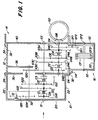
- the gear shift transmission module 10 is essentially hat-shaped, ie it has a base flange 20 and lateral surfaces 22 and is open on the side opposite the base flange 20 .
- a suitable flange 24 is preferably provided in the region of the open side, through which the gear shift transmission module 10 can be fastened to an adjacent transmission module.
- the adjacent transmission module can, for example, as shown in FIG. 1, be a group transmission module 12.
- the group transmission module 12 is likewise hat-shaped in a similar manner and contains a bottom flange 30, lateral surfaces 32 and a flange 34. Furthermore, the group transmission module 12 preferably contains an inner wall 36 which is designed as a shaft support structure, which will be discussed in more detail below.
- the differential housing 14 can have any suitable shape, provided that it has a base area 40, through which it covers the open side of the group transmission module 12. If for some reason the group transmission module 12 is not to be arranged directly on the differential housing 14, but rather is to be arranged at a distance from it, this requirement can also be dispensed with by the open side of the group transmission module 12 not being closed by the base 40, but by another plate .
- the front-wheel drive transmission module 16 is also hat-shaped and contains a bottom flange 50, lateral surfaces 52 and a flange 54, with which it can be fastened via an opening in the lateral surface 32 of the group transmission module 12.
- the open side of the front-wheel drive transmission module 16 is closed by the outer surface 32 of the group transmission transmission module 12.
- the bottom flanges 20, 30, 40 and the outer surfaces 32, 52 of the transmission modules 10, 12 , 14, 16 suitable passages. If certain shafts or passages are not required for a specific application, the passages can be closed by corresponding covers, not shown. For example, if front wheel drive is not required, the front wheel drive transmission module can 16 omitted and a cover can be screwed over the opening in the lateral surface 32 of the group transmission module 12.
- a shaft S1 is rotatably arranged in the gearshift transmission module 10 and is aligned with a shaft S3, which is located within the group shift transmission module 12.
- the right end of the shaft S3 is rotatably supported in the bottom flange 40 of the differential case 14.
- the left end of the shaft S3 is rotatably supported in the bottom flange 30 of the group transmission module 12.
- the left end of the shaft S1 is rotatably supported in the bottom flange 20 of the gear transmission module 10, and its right end is rotatably supported within a recess in the left end of the shaft S3.
- the gears G1R, G11, G12 are rotatably mounted on the shaft S1. Clutches CR, C1, C2, C3 are also arranged on shaft S1.
- the gears G1R, G11, G12 can be connected non-rotatably to the shaft S1 by means of the couplings CR, C1, C2, and the shafts S1 and S3 can optionally be non-rotatably connected to one another by the coupling C3.
- the left end of a shaft S2 is rotatably supported in the bottom flange 20 of the gear shift transmission module 10.
- the right end of the shaft S2 projects through an opening in the bottom flange 30 of the group transmission module 12 and is rotatably mounted in the inner wall 36 of the group transmission module 12.
- the gears G2R, G21, G22, G20 are arranged on the shaft S2 in a rotationally fixed manner.
- the gears G21 and G22 mesh with the gears G11 and G12.
- the gear wheel G20 of the shaft S2 is located within the group transmission module 12.
- the bottom flange 20 of the gearshift transmission module 10 carries an idler shaft SI, on which a reverse gear GIR is rotatably mounted, which constantly meshes with the gears G2R and G1R.
- the gears G3D, G3C, G3B, G3A are arranged on the shaft S3 in a rotationally fixed manner.
- the G3D gear constantly meshes with the G20 gear.
- the left end of a shaft S4 is in the bottom flange 30 of the group transmission module 12, and the right end of this shaft S4 is rotatably mounted in the bottom flange 40 of the differential case 14.
- the gears G4D, G4C, G4B, G4A are rotatably mounted on the shaft S4 within the group transmission module 12.
- the shaft S4 carries a non-rotatable gear G40 within the group transmission module 12 and a non-rotatable bevel gear GB within the differential housing 14.
- a differential gear GD is rotatably arranged, with which the bevel gear GB meshes continuously.
- the gears G4D, G4C, G4B, G4A can optionally be connected to the shaft S4 in a rotationally fixed manner by means of associated couplings SD, SS, SB, SA.
- a shaft SF1 is rotatably supported by a lateral surface 52 of the front wheel drive gear housing 16. On it a double gear is rotatably mounted, which has two gears GF1, GF2. The toothing GF1 constantly meshes with the gear wheel G40.
- a shaft SF2 is rotatably supported on two lateral surfaces 52 of the front wheel drive gear housing 16. It protrudes from the front wheel drive housing 16 with at least one end (not shown) to connect to the front wheel drive mechanism.
- the gear wheel GF3, which is in constant engagement with the toothing GF2, is rotatably arranged on the shaft SF2 and can optionally be connected in a rotationally fixed manner to the shaft SF2 by means of a coupling CF.
- the shaft S4 outputs the output power from the group transmission module 12 via the bevel gear GB to the differential gear GD. If a front wheel drive transmission module 16 (as shown) is installed, the output power can branch out and a part can be delivered to the front wheel drive transmission module 16 via the gear wheel G40. If the clutch CF is engaged, power is delivered to the front wheels, not shown. If a front wheel drive transmission module 16 is not provided, the gear wheel G40 can in principle also be omitted.
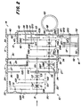
- the gear arrangement according to FIG. 2 contains two further gear modules. Between the gear shift module 10 and the group shift module 12, an intermediate shift module 11 is inserted, which is also essentially hat-shaped and contains a bottom flange 26, lateral surfaces 27 and a flange 28. As shown, the open side of the gear shift module 10 is essentially through the bottom flange 26 of the intermediate shift module 11 closed, while the bottom flange 30 of the group transmission module 12 essentially closes the open side of the intermediate transmission module 11.
- the intermediate transmission module 11 also has an intermediate wall 29 which is located essentially at a location corresponding to the inner wall 36 of the group transmission module 12 shown in FIG. 1.
- the inner wall 36 of the group transmission module 12 can be omitted in the exemplary embodiment according to FIG. 2 if this is considered to be expedient, but it can also be retained in order to enable a simple, later transmission conversion.
- the shafts S3 and S4 are rotatably mounted in the base flanges 30 and 40. 1, however, the left end of the shaft S3 received the shaft S1, it now carries the right end of a shaft S5 which extends in the intermediate gear module 11. 1, the shaft S1 is rotatably mounted in the shaft S3, according to FIG. 2 the shaft S5 is connected to the shaft S3 in a rotationally fixed manner via splines or the like. The left end of the shaft S5 is rotatably mounted in the bottom flange 26 of the intermediate gear module 11 and rotatably receives the right end of the shaft S1 in a bearing in essentially the same way as it is with reference to FIG.
- shaft C3 (and thus indirectly shaft S3) can also be connected in a rotationally fixed manner to shaft S1 by coupling C3.
- the S5 shaft rotatably supports the G5F and G5E gears.
- the G20 gear constantly meshes with the G3D gear.
- a shaft S6 is rotatably mounted in the bottom flanges 26 and 30 within the intermediate gear module 11. Your one end is over a spline or otherwise rotatably connected to the shaft S4.
- the gears G6F and G6E are rotatably mounted on the shaft S6 and constantly mesh with the gears G5F and G5E.
- the S6 shaft carries the CF and CE couplings, through which the gears G6F and G6E can optionally be connected to the S6 shaft in a rotationally fixed manner.
- the auxiliary transmission module 13 contains a bottom flange 42, a lateral surface 43 and a flange 44, through which the auxiliary transmission module 13 can be fastened to the bottom surface 40 of the differential housing 14.
- a corresponding cover plate 45 is fastened on the other side of the bottom surface 40 within the differential housing 14.
- a double gearwheel is rotatably mounted on shaft S7 and has two gears G71, G72.
- the G71 toothing constantly meshes with the G3A gear.
- a double gearwheel is also rotatably mounted on the shaft S8 and has two toothings G81, G82.
- the toothing G81 constantly meshes with the toothing G72, and the toothing G82 constantly meshes with the gear G4A.
- the gear ratio of the additional gear module 13 further reduces the reduction in area A. That in connection with the 18-speed transmission
- the additional transmission module 13 shown can, if desired, also be added to a 12-speed transmission.
- the gear arrangement of the additional transmission module 13 can be changed without difficulty and adapted to different requirements. By changing the double gears rotatably mounted on the shafts S7 and S8, large changes in the reduction ratios can easily be realized. Furthermore, the cover plate 45 can be omitted if other fastening options for the shafts S7 and S8 are provided.
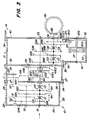
- FIG. 3 there is also an intermediate gear module 11 between the gear shift module 10 and the group gear module 12.
- a creeper gear was inserted instead of the additional range gears.
- the cross section through the transmission has been shown slightly modified, in that the shaft S2 is divided and shown with its right end, which projects into the intermediate transmission module 11, in the vicinity of the upper lateral surface 27.
- the outer gear structure essentially corresponds to that shown in FIG. 2.
- a creeper shaft SC is located at approximately the same location as the shaft S5 in the embodiment shown in FIG. 2, that is, the right end of the creeper shaft SC is carried by the shaft S3 and its left end is mounted in the bottom flange 26 and rotatably supports the shaft S1.
- the left end of the creeper shaft SC can be connected to shaft S1 in a rotationally fixed manner by means of a coupling C3.
- the right end of the creeper shaft SC is rotatably mounted in the shaft S3 and does not have a spline in connection with this.
- the gear wheels GC1 and GC2 are arranged on the creeper shaft SC in a rotationally fixed manner, the gear wheel GC1 constantly meshing with the gear wheel G20.
- the gear wheel G3C1 is arranged in a rotationally fixed manner on a section of the shaft S3 which projects into the intermediate gearbox module 11.
- Gear G3C2 is rotatably supported over the same portion of shaft S3.
- a shaft S9 is rotatably supported between the base flanges 26 and 30 and supports the two gears G91 and G92, which mesh constantly with the gears GC2 and G3C2.
- the creeper shaft SC carries the clutches CC1 and CC2. Through the clutch CC1, the shaft S3 can be connected in a rotationally fixed manner to the creeper shaft SC, so that the creeper is avoided.
- the clutch CC2 is preferably a shift pin clutch, by means of which the shaft S3 can optionally be connected in a rotationally fixed manner to the gear wheel G3C2 in order to switch on the creeper gear.
- FIG. 4 shows a transmission which contains all the modules described so far.
- This transmission structure is similar to that shown in FIG. 3, but additionally contains the shaft S6 with the associated gear wheels G6F, G6E and clutches CF, CE, which have been described with reference to FIG. 2.
- the gears G6F and G6E constantly mesh with the gears GC1 and G3C1 of the shaft SC and not, as shown in FIG. 3, with the gears G5F and G5E of the shaft S5.
- the gear modules described allow extremely high flexibility with regard to gear mounting, in which a large number of different gears with different requirements can be implemented by selection and simple assembly of the gear modules.
- the exact transmission ratio can be given for given transmission modules easily adapt individual groups or gears to requirements, whereby a basic gear of the translation can remain the same. This is achieved in that some of the gears are replaced by gears of the same diameter but with different numbers of teeth.
- the change in the gear ratio can be achieved by the principle of the profile shift.
- the modular gearbox consists of simple components that can be manufactured in large quantities and at reasonable prices.
Abstract
Description
Die Erfindung betrifft ein Getriebe für Kraftfahrzeuge, insbesondere für landwirtschaftliche oder Nutzfahrzeuge, das mehrere Getriebeeinheiten enthält, die wahlweise modular zusammensetzbar sind und ein vielgängiges Getriebe bilden.The invention relates to a transmission for motor vehicles, in particular for agricultural or commercial vehicles, which contains a plurality of transmission units which can optionally be assembled in a modular manner and form a multi-speed transmission.
Bei Arbeitsfahrzeugen, wie Land- und Nutzfahrzeugen, werden in der Regel Getriebe mit einer Vielzahl von Gängen verwendet. Die tatsächliche und die erforderliche Anzahl der Übertragungsverhältnisse variiert von Anwendungsfall zu Anwendungsfall.Gearboxes with a large number of gears are generally used in work vehicles, such as land and commercial vehicles. The actual and the required number of transmission ratios varies from application to application.
Die Herstellungsstückzahlen der Getriebe für einen besonderen Anwendungsfall können relativ klein sein. Die Konstruktion und Fertigung kleiner Serien ist jedoch teuer. Es wird daher angestrebt, ein Getriebe in Modulbauweise auszuführen, so daß sich verschiedene Getriebekomponenten auf verschiedene Weise zusammensetzen lassen, um den besonderen Anforderungen Rechnung zu tragen.The production quantities of the gearboxes for a special application can be relatively small. However, the design and manufacture of small series is expensive. It is therefore desirable to carry out a gearbox in a modular design so that different gearbox components can be assembled in different ways in order to take account of the special requirements.
In der gattungsbildenden DE-A-31 37 805 wird ein modularer Getriebeaufbau gefordert, um einfachere und technisch anspruchsvollere Getriebekombinationen aus einer verhältnismäßig geringen Anzahl baugleicher Einzelkomponenten zu erstellen. Auf die mit dieser Zielsetzung verbundenen konstruktiven Schwierigkeiten wird jedoch nicht eingegangen.In the generic DE-A-31 37 805, a modular transmission structure is required in order to create simpler and technically more sophisticated transmission combinations from a relatively small number of identical individual components. However, the constructive difficulties associated with this objective are not dealt with.
Die der Erfindung zugrunde liegende Aufgabe wird darin gesehen, ein modular zusammensetzbares Kraftfahrzeuggetriebe anzugeben, das den einfachen Aufbau einer Vielzahl unterschiedlicher Getriebestrukturen aus mehreren Getriebeeinheiten zuläßt.The object on which the invention is based is seen in specifying a modular motor vehicle transmission which has the simple structure of a large number of different ones Allows gear structures from multiple gear units.
Die Aufgabe wird ausgehend von dem Oberbegriff des Patentanspruches 1 durch dessen kennzeichnende Merkmale gelöst. Weitere vorteilhafte Ausgestaltungen und Weiterbildungen der Erfindung gehen aus den Unteransprüchen hervor.The object is achieved on the basis of the preamble of claim 1 by its characterizing features. Further advantageous refinements and developments of the invention emerge from the subclaims.
Als Getriebeeinheiten kommen beispielsweise ein Gangschaltgetriebemodul, ein oder mehrere Gruppenschaltgetriebemodule, ein Kriechganggetriebemodul, ein Vorderradantriebsgetriebemodul und ein Lastschaltgetriebemodul in Betracht. Diese lassen sich wahlweise in unterschiedlichen Kombinationen zusammenbauen, um für unterschiedliche Anwendungen unterschiedliche Übertragungsbedingungen zu erhalten. Das aus den Getriebeeinheiten zusammengesetzte Gesamtgetriebe kann beispielsweise zwischen der Antriebsmaschine und dem Achsdifferential des Fahrzeugs eingefügt werden.Possible gear units are, for example, a gear shift module, one or more group shift modules, a creeper gear module, a front wheel drive gear module and a powershift gear module. These can optionally be assembled in different combinations in order to obtain different transmission conditions for different applications. The overall transmission composed of the transmission units can be inserted, for example, between the drive machine and the axle differential of the vehicle.
Einzelne Getriebeeinheiten sind im wesentlichen hutförmig ausgebildet. Sie weisen auf einer Gehäuseseite einen Bodenflansch auf, an den sich eine mehr oder weniger geschlossene Seitenwandung anschließt, durch die die Getriebeverzahnungen geschützt werden und die das Getriebeöl auffängt. Auf der dem Bodenflansch gegenüberliegenden Getriebemodulseite befindet sich eine Gehäuseöffnung, welche durch den Bodenflansch eines benachbarten Getriebegehäuses nach außen verschließbar ist. Wenigstens eine Getriebeeinheit enthält eine oder mehrere Getriebewellen, die einenends in dem Bodenflansch des zugehörigen Getriebegehäuses gelagert sind und sich anderenends frei in die Gehäuseöffnung des Getriebegehäuses erstrecken. Die Anordnung und Lagerung der Getriebewellen wird so vorgenommen, daß sich eine aus dem Getriebegehäuse, den zugehörigen Getriebewellen sowie gegebenenfalls weiteren Komponenten bestehende vormontierbare Getriebeeinheit ergibt. Die sich frei in die Gehäuseöffnung des Getriebegehäuses erstreckenden Enden der Getriebewellen stützen sich nach dem Zusammenbau mit einer benachbarten Getriebeeinheit am Bodenflansch oder einer geeigneten Aufnahme der benachbarten Getriebeeinheit ab. Der Bodenbereich des benachbarten Getriebegehäuses dient dabei gleichzeitig als Deckelflansch für das Getriebegehäuse.Individual gear units are essentially hat-shaped. They have a bottom flange on one side of the housing, which is followed by a more or less closed side wall, through which the gear teeth are protected and which catches the gear oil. On the gear module side opposite the base flange there is a housing opening which can be closed to the outside by the base flange of an adjacent gear housing. At least one gear unit contains one or more gear shafts, which are mounted on one end in the bottom flange of the associated gear housing and on the other end extend freely into the housing opening of the gear housing. The arrangement and mounting of the gear shafts is carried out in such a way that a preassembled gear unit results from the gear housing, the associated gear shafts and possibly other components. Which The ends of the transmission shafts that extend freely into the housing opening of the transmission housing are supported after assembly with an adjacent transmission unit on the base flange or a suitable receptacle for the adjacent transmission unit. The bottom area of the adjacent gear housing also serves as a cover flange for the gear housing.
Die modulare Ausbildung des Getriebes, bei dem jede Welle bzw. jeder Wellenabschnitt lediglich einem hutförmig (oder topfförmig) ausgebildeten Getriebegehäuse zugeordnet ist, gestattet die komplette Vormontage der Wellen mit den zugehörigen Zahnrädern, Kupplungen, Lagern, Dichtungen und dergleichen außerhalb des Getriebegehäuses. Es können somit beispielsweise die notwendigen Axialspiele der Schalträder (z. B. Synchronräder) leicht eingestellt und geprüft werden. Erst nach der Vormontage der Wellen werden diese mit einem Ende in das nach einer Seite hin offene Getriebegehäuse eingesetzt. Das Getriebegehäuse wird dann mit der Schaltung für Schalteinheiten (z. B. Synchronisiereinheiten) komplettiert und steht schließlich zum Zusammenbau mit einer weiteren vormontierten Getriebeeinheit zur Verfügung. Bei dem Zusammenbau werden die in Richtung der oder durch die Gehäuseöffnung ragenden Wellenenden in Lagerstellen eingesteckt, die von der Außenseite des Bodenflanschs des benachbarten Getriebegehäuses in diesen eingelassen sind.The modular design of the transmission, in which each shaft or each shaft section is assigned only to a hat-shaped (or pot-shaped) transmission housing, permits the complete preassembly of the shafts with the associated gear wheels, couplings, bearings, seals and the like outside the transmission housing. For example, the necessary axial play of the ratchet wheels (e.g. synchronous wheels) can be easily set and checked. Only after the pre-assembly of the shafts are they inserted with one end into the gear housing, which is open on one side. The gear housing is then completed with the circuit for switching units (e.g. synchronizing units) and is finally available for assembly with another pre-assembled gear unit. During assembly, the shaft ends protruding in the direction of or through the housing opening are inserted into bearing points which are embedded in the adjacent gear housing from the outside of the base flange.
Das sich frei in die Getriebegehäuseöffnung erstreckende Wellenende kann unmittelbar über eine Lagerstelle im Bodenflansch der benachbarten Getriebeeinheit abgestützt werden. Es ist in vielen Fällen jedoch vorteilhaft, daß zwei benachbarte Getriebeeinheiten so angeordnet werden, daß wenigstens zwei ihrer Wellen miteinander fluchten. Der die beiden Getriebeeinheiten trennende Bodenflansch weist eine Öffnung auf, durch die sich eine der Wellen erstreckt und in der diese Welle gelagert ist. Das freie Ende dieser Welle trägt eine konzentrische Lagerstelle, die der Aufnahme des Wellenendes der anderen Welle dient. Die Lagerstelle kann entweder eine Keilverzahnung enthalten, durch die eine formschlüssige Verbindung zwischen den Wellen herstellbar ist, oder sie kann als Drehlagerung, beispielsweise als Nadellagerung ausgebildet sein, die eine Verdrehung der Wellen gegeneinander zuläßt. Bei einer Drehlagerung ist vorzugsweise eine Kupplung vorgesehen, durch die wahlweise die beiden Wellen drehfest miteinander verbindbar sind, wodurch sich in vielen Fällen ein zusätzlicher Gang realisieren läßt.The shaft end, which extends freely into the transmission housing opening, can be supported directly via a bearing in the bottom flange of the adjacent transmission unit. In many cases, however, it is advantageous that two adjacent gear units are arranged so that at least two of their shafts are aligned with one another. The bottom flange separating the two gear units has an opening through which one of the shafts extends and in which this shaft is mounted. The free end of this wave carries a concentric bearing that serves to accommodate the shaft end of the other shaft. The bearing point can either contain a spline through which a positive connection between the shafts can be produced, or it can be designed as a rotary bearing, for example as a needle bearing, which allows the shafts to be rotated relative to one another. In the case of a rotary bearing, a coupling is preferably provided, by means of which the two shafts can optionally be connected to one another in a rotationally fixed manner, whereby an additional gear can be realized in many cases.
Vorzugsweise ist eine der hutförmigen Getriebeeinheiten ein Gangschaltgetriebemodul, in dessen Bodenflansch eine Eingangswelle mit wenigstens zwei durch Schalteinheiten einrückbare Losräder sowie eine Festräderwelle mit wenigstens zwei mit den Losrädern kämmende Festräder gelagert sind. Die Festräderwelle trägt im Bereich ihres zweiten, freien Endes ein weiteres Festrad, das mit einem Eingangszahnrad einer benachbarten Getriebeeinheit kämmt. Nach der Montage des Gangschaltgetriebemoduls an einer benachbarten Getriebeeinheit (z. B. einem Gruppenschaltgetriebemodul) stützen sich die zweiten Enden der Eingangswelle und der Festräderwelle am Bodenflansch bzw. einer geeigneten Aufnahme der benachbarten Getriebeeinheit ab. Das freie Ende der Eingangswelle des Gangschaltgetriebemoduls ist zweckmäßigerweise in einer Ausnehmung des Wellenendes einer Welle der benachbarten Getriebeeinheit drehbar gelagert. Ferner sind beide Wellen durch eine einrückbare Schaltverzahnung drehfest miteinander verbindbar. Durch ein derartiges Gangschaltgetriebemodul lassen sich 3 Vorwärtsgänge realisieren. Hierbei kann das übliche Losrad für den dritten Gang eingespart werden, weil das weitere Festrad der Festräderwelle unmittelbar mit einem auf der Getriebewelle der benachbarten Getriebeeinheit angeordneten Eingangszahnrad kämmt.Preferably, one of the hat-shaped gear units is a gear shift transmission module, in the bottom flange of which an input shaft with at least two idler gears that can be engaged by shifting units and a fixed gear shaft with at least two fixed gears meshing with the idler gears are mounted. The fixed gear shaft carries a further fixed gear in the region of its second, free end, which meshes with an input gear of an adjacent gear unit. After the gear shift transmission module has been installed on an adjacent transmission unit (e.g. a group transmission transmission module), the second ends of the input shaft and the fixed gear shaft are supported on the base flange or a suitable receptacle of the adjacent transmission unit. The free end of the input shaft of the gear shift transmission module is expediently rotatably mounted in a recess in the shaft end of a shaft of the adjacent transmission unit. Furthermore, both shafts can be connected to one another in a rotationally fixed manner by means of an engaging gear teeth. With such a gear shift module, 3 forward gears can be realized. The usual idler gear for third gear can be saved here because the further fixed gear of the fixed gear shaft meshes directly with an input gear arranged on the gear shaft of the adjacent gear unit.
Eine bevorzugte Ausgestaltung des Gangschaltgetriebemoduls sieht vor, daß die Eingangswelle ein drittes durch eine Schalteinheit einrückbares Losrad und die Festräderwelle ein drittes Festrad trägt und daß das dritte Losrad und das dritte Festrad über ein im Gangschaltgetriebegehäuse drehbar gelagertes Umkehrrad miteinander in Eingriff stehen. Hierdurch wird ein Rückwärtsgang realisiert. Vorzugsweise ist das Gangschaltgetriebemodul am Anfang des Getriebestranges angeordnet, so daß die Schaltstelle für den Rückwärtsgang am Anfang des Getriebestranges liegt. Hierdurch kann die Schaltarbeit (z. B. Synchronarbeit) beim Umschalten von Rückwärtsfahrt auf den ersten Vorwärtsgang oder umgekehrt sehr gering gehalten werden, da lediglich die Trägheitsmassen der Kupplungsnabe mit den zugehörigen Lamellen sowie die Eingangswelle des Gangschaltgetriebemoduls beherrscht werden müssen. Dies ermöglicht es, bei noch rollendem Fahrzeug eine schnelle Umschaltung der Fahrtrichtung vorzunehmen, ohne daß die beim Umschalten betätigte Schaltstelle übermäßig belastet wird.A preferred embodiment of the gearshift transmission module provides that the input shaft carries a third idler gear which can be engaged by a shift unit and the fixed gear shaft carries a third fixed gear and that the third idler gear and the third fixed gear engage with one another via a reversing gear which is rotatably mounted in the gearshift transmission housing. This creates a reverse gear. The gearshift transmission module is preferably arranged at the beginning of the transmission train, so that the switching point for the reverse gear is at the beginning of the transmission train. As a result, the switching work (e.g. synchronous work) when switching from reverse to the first forward gear or vice versa can be kept very low, since only the inertial masses of the clutch hub with the associated plates and the input shaft of the gear shift transmission module have to be mastered. This enables the direction of travel to be switched over quickly while the vehicle is still rolling without the switch point actuated during the switchover being subjected to excessive stress.
Gemäß einer weiteren Ausgestaltung der Erfindung ist eine der hutförmigen Getriebeeinheiten ein Gruppenschaltgetriebemodul, in dessen Bodenflansch wenigstens eine Festräderwelle und wenigstens eine Losräderwelle gelagert sind, die einander zugeordnete Paare aus Festrädern und Losrädern tragen, wobei die Losräder durch Schalteinheiten drehfest mit der Losräderwelle verbindbar sind.According to a further embodiment of the invention, one of the hat-shaped gear units is a group manual transmission module, in the bottom flange of which at least one fixed gear shaft and at least one idler gear shaft are mounted, which carry mutually associated pairs of fixed gears and idler gears, the idler gears being rotatably connected to the idler gear shaft by switching units.
Eine weitere hutförmige Getriebeeinheit ist vorzugsweise als Zwischenschaltgetriebemodul ausgebildet, das beispielsweise zwischen einem Gangschaltgetriebemodul und einem Gruppenschaltgetriebemodul einfügbar ist. Es handelt sich bei dem Zwischenschaltgetriebe beispielsweise um ein weiteres Gruppenschaltgetriebe, durch das sich die Zahl der schaltbaren Gruppen erhöhen läßt. Auch in dem Zwischenschaltgetriebegehäuse sind eine Festräderwelle und eine Losräderwelle angeordnet, die einander zugeordnete Paare aus Festrädern und Losrädern tragen, wobei die Losräder durch Schalteinheiten drehfest mit der Losräderwelle verbindbar sind. Beide Wellen sind mit ihrem jeweils ersten Ende im Bodenflansch des Zwischenschaltgetriebegehäuses gelagert und erstrecken sich mit ihrem jeweils zweiten Ende frei in die dem Bodenflansch gegenüberliegende Öffnung des Zwischenschaltgetriebegehäuses. Die Festräderwelle dient als Eingangswelle des Zwischenschaltgetriebemoduls und ist zweckmäßigerweise mit der Festräderwelle des nachgeordneten Gruppenschaltgetriebemoduls drehfest verbunden. Ferner ist vorzugsweise die Losräderwelle mit der Losräderwelle des nachgeordneten Gruppenschaltgetriebemoduls drehfest verbunden. Die Verbindung der Wellen kann durch Kupplungsverzahnungen erfolgen. (Fig. 2).Another hat-shaped gear unit is preferably designed as an intermediate gearbox module, which can be inserted, for example, between a gearshift gearbox module and a group gearbox module. The intermediate transmission is, for example, a further group transmission, by means of which the number of switchable groups can be increased. A fixed gear shaft and an idler gear shaft are also arranged in the intermediate gearbox housing. which carry associated pairs of fixed gears and idler gears, the idler gears being rotatably connected to the idler gear shaft by switching units. Both shafts are mounted with their first end in the bottom flange of the intermediate gearbox housing and extend freely with their second end into the opening of the intermediate gearbox housing opposite the bottom flange. The fixed gear shaft serves as the input shaft of the intermediate gear module and is expediently non-rotatably connected to the fixed gear shaft of the downstream group gear module. Furthermore, the idler gear shaft is preferably rotatably connected to the idler gear shaft of the subordinate group transmission module. The shafts can be connected by coupling teeth. (Fig. 2).
Zur Änderung der Übersetzungsverhältnisse des Gruppenschaltgetriebemoduls (und auf entsprechende Weise auch des Zwischenschaltgetriebemoduls) lassen sich auf einfache Weise einerseits die Festräderwelle und andererseits die Losräder der Losräderwelle gegen eine andere Festräderwelle bzw. andere Losräder austauschen. Das Gruppengetriebegehäuse, die Lage der Schalteinrichtungen und die benachbarten Getriebegehäuse brauchen dabei nicht geändert zu werden. Daher können Gruppengetriebe mit unterschiedlichen Übertragungsverhältnissen unter Verwendung weitgehend gleicher Bauteile kostengünstig hergestellt werden.In order to change the gear ratios of the group transmission module (and in a corresponding manner also the intermediate transmission module), the fixed gear shaft and on the other hand the idler gears of the idler gear shaft can be easily replaced by another fixed gear shaft or other idler gears. The group gearbox, the position of the switching devices and the adjacent gearbox need not be changed. Group transmissions with different transmission ratios can therefore be manufactured inexpensively using largely the same components.
Beim Zusammenbau kann zunächst eine ausgewählte Festräderwelle und eine für alle Anwendungen gleiche Losräderwelle in Lagerstellen des sich auf der offenen Seite des Gruppenschaltgetriebemoduls anschließenden Getriebegehäuses, z. B. des Differentialgetriebegehäuses montiert werden. Dann werden die Losräder und Schalteinheiten ausgewählt und auf der Losräderwelle montiert. Hierauf wird das hutförmige Gruppenschaltgetriebegehäuse über die Wellen gestülpt, so daß die ersten Enden der Wellen von Lagerstellen im Bodenflansch des Gruppenschaltgetriebegehäuses aufgenommen werden. Schließlich wird der auf der offenen Seite des Gruppenschaltgetriebegehäuses liegende Flansch am Differentialgetriebegehäuse befestigt.When assembling, a selected fixed gear shaft and an idler gear shaft that is the same for all applications can be used in the bearing positions of the gear housing that adjoins the open side of the group transmission module, e.g. B. the differential gear housing. Then the idler gears and shift units are selected and mounted on the idler gear shaft. Then the hat-shaped group gearbox is slipped over the shafts, so that the first ends of the shafts of bearings in the bottom flange of the group transmission housing are received. Finally, the flange located on the open side of the group transmission housing is attached to the differential gear housing.
An die Außenseite des Bodenflanschs des Gruppenschaltgetriebegehäuses schließt sich vorzugsweise die offene Seite des Gangschaltgetriebegehäuses an. Ferner kämmt ein Festrad der Festräderwelle des Gangschaltgetriebemoduls mit einem Festrad der Festräderwelle des Gruppenschaltgetriebemoduls. Hierdurch kann, wie bereits erwähnt, ein Zahnrad für den dritten Gang eingespart werden. Die Festräderwelle des Gruppenschaltgetriebemoduls ragt zweckmäßigerweise durch eine Öffnung in dem Bodenflansch des Gruppenschaltgetriebemoduls in dieses hinein.The open side of the gear shift housing preferably adjoins the outside of the base flange of the group shift transmission case. Furthermore, a fixed gear of the fixed gear shaft of the gear shift transmission module meshes with a fixed gear of the fixed gear shaft of the group shift gear module. As already mentioned, this enables a gearwheel for the third gear to be saved. The fixed gear shaft of the group transmission module expediently protrudes through an opening in the bottom flange of the group transmission module.
Eine weitere Ausgestaltung der Erfindung sieht vor, daß ein Festrad der Festräderwelle des Gruppenschaltgetriebemoduls (oder des Zwischenschaltgetriebemoduls) als Eingangszahnrad dient und einerseits mit dem weiteren Festrad der Festräderwelle des Gangschaltgetriebemoduls und andererseits mit einem Losrad der Losräderwelle des Gruppenschaltgetriebemoduls kämmt. Das Eingangszahnrad erfüllt somit zwei Aufgaben: erstens ist es wirkungsmäßig Bestandteil des Gangschaltgetriebemoduls, in dem es den Kraftfluß von der Festräderwelle des Gangschaltgetriebemoduls aufnimmt, und zweitens ist es Bestandteil des Gruppenschaltgetriebemoduls und bedient ein durch eine Schaltstelle schaltbares Losrad. Es kann somit gegenüber einem konventionellen Getriebe ein Zahnrad entfallen.A further embodiment of the invention provides that a fixed gear of the fixed gear shaft of the group transmission module (or of the intermediate gear module) serves as an input gear and meshes on the one hand with the further fixed gear of the fixed gear shaft of the gear shift module and on the other hand with an idler gear of the idler gear shaft of the group transmission module. The input gear thus fulfills two tasks: firstly, it is an effective component of the gearshift transmission module, in which it absorbs the power flow from the fixed gear shaft of the gearshift transmission module, and secondly, it is part of the group manual transmission module and operates an idler gear that can be switched by a switching point. Compared to a conventional gearbox, a gearwheel can thus be omitted.
Gemäß einer bevorzugten Ausgestaltung der Erfindung kann ein auf einer Losradwelle gelagertes Losrad, das mit dem Zahrad einer Festradwelle kämmt, gegen ein anderes Losrad ausgetauscht werden, das zwar den gleichen Durchmesser, jedoch eine unterschiedliche Zähnezahl aufweist. Diese Lösung ermöglicht es, daß beispielsweise bei Getrieben gemäß Fig. 3 oder 4 die Gruppen E und D unterschiedliche Übersetzungsverhältnisse bei gleichem Achsabstand haben, obwohl die Zahnräder G5F und G3D in ihrer Zahngeometrie gleich sind. Daher läßt sich das Gruppenschaltgetriebemodul ohne Räderaustausch auch unmittelbar an Stelle des Zwischenschaltgetriebemoduls an dem Gangschaltgetriebemodul anflanschen.According to a preferred embodiment of the invention, an idler gear mounted on an idler gear shaft, which meshes with the gear of a fixed gear gear shaft, can be exchanged for another idler gear that has the same diameter, however has a different number of teeth. This solution makes it possible, for example in the case of transmissions according to FIG. 3 or 4, for groups E and D to have different transmission ratios with the same center distance, although the gears G5F and G3D are identical in their tooth geometry. Therefore, the group transmission module can be flanged to the gear transmission module directly instead of the intermediate transmission module without changing the wheels.
Eine unterschiedliche Zähnezahl, wie im oben beschriebenen Fall bei sonst gleichen Zahnrädern und gleichbleibendem Achsabstand läßt sich durch das Prinzip der Profilverschiebung erreichen, die es ermöglicht, die Zähnezahl eines mit einem gleichen Basiszahnrad kämmenden Zahnrades in gewissen Grenzen gegenüber einer optimalen Zähnezahl zu erhöhen oder zu vermindern. Beispielsweise können mit einem Basiszahnrad zwei unterschiedliche Zahnräder kämmen, deren Zähnezahl sich um beispielsweise 3 bis 4 Zähne unterscheiden.A different number of teeth, as in the case described above with otherwise identical gears and constant center distance, can be achieved by the principle of the profile shift, which makes it possible to increase or decrease the number of teeth of a gear meshing with the same basic gear within certain limits compared to an optimal number of teeth . For example, two different gearwheels, the number of teeth of which differ by, for example, 3 to 4 teeth, can mesh with a base gearwheel.
Vorzugsweise ist eine weitere hutförmige Getriebeeinheit als Kriechgangschaltgetriebemodul ausgebildet, das sich beispielsweise zwischen das Gangschaltgetriebegehäuse und das Gruppenschaltgetriebegehäuse einfügen läßt. In dem Kriechgangschaltgetriebegehäuse sind eine Kriechgangeingangswelle und eine Nebenwelle angeordnet, die mit ihrem jeweils ersten Ende im Bodenflansch des Kriechgangschaltgetriebemoduls gelagert sind und sich mit ihrem jeweils zweiten Ende frei in die dem Bodenflansch gegenüberliegende Öffnung des Kriechgangschaltgetriebegehäuses erstrecken. Das auf der Kriechgangeingangswelle angeordnete Festrad kämmt mit einem relativ großen Festrad der Nebenwelle, und ein relativ kleines Festrad der Nebenwelle kämmt mit einem konzentrisch zur Kriechgangeingangswelle gelagerten Losrad. Ferner läßt sich die Kriechgangeingangswelle oder das Losrad wahlweise drehfest mit der Festräderwelle des nachgeordneten Gruppenschaltgetriebemoduls in Eingriff bringen (Fig. 3).Another hat-shaped gear unit is preferably designed as a creeper gearbox module, which can be inserted, for example, between the gearbox gearbox and the group gearbox. Arranged in the creeper gearbox are a creeper input shaft and a secondary shaft, each of which is mounted with its first end in the bottom flange of the creeper gear module and with its second end extends freely into the opening of the creeper gearbox housing opposite the bottom flange. The fixed gear arranged on the creeper input shaft meshes with a relatively large fixed gear of the auxiliary shaft, and a relatively small fixed gear of the auxiliary shaft meshes with an idler gear mounted concentrically to the creeper input shaft. Furthermore, the creeper input shaft or the idler gear can be rotated with the Bring the fixed gear shaft of the subordinate group transmission module into engagement (Fig. 3).
Vorzugsweise ist das zweite Ende der Kriechgangeingangswelle drehbar in einer Ausnehmung der Festräderwelle des nachgeordneten Gruppenschaltgetriebemoduls gelagert. Ferner ist es von Vorteil, wenn auf einem drehfest mit der Festräderwelle eines nachgeordneten Gruppenschaltgetriebemoduls verbundenen Wellenabschnitt eine Schalteinrichtung, beispielsweise eine Schaltmuffe, angeordnet ist, die die Festräderwelle des Gruppenschaltgetriebemoduls wahlweise mit einem drehfest auf der Kriechgangeingangswelle angeordneten Kupplungskörper oder dem Losrad kuppelt.Preferably, the second end of the creeper input shaft is rotatably mounted in a recess of the fixed gear shaft of the downstream group transmission module. Furthermore, it is advantageous if a switching device, for example a gearshift sleeve, is arranged on a shaft section that is non-rotatably connected to the fixed gear shaft of a downstream group shift transmission module and that optionally couples the fixed gear shaft of the group shift transmission module with a clutch body or the idler gear arranged on the creeper input shaft in a rotationally fixed manner.
Eine Ausgestaltung der Erfindung, die eine sehr kompakte Bauweise ermöglicht, sieht vor, daß im Bereich des freien zweiten Endes der Kriechgangeingangswelle ein zu dieser konzentrischer hohler Wellenabschnitt drehbar gelagert ist, der über eine Keilverzahnung drehfest mit der Festräderwelle des nachgeordneten Gruppenschaltgetriebemoduls verbindbar ist. Der hohle Wellenabschnitt trägt in seinem mittleren Bereich ein drehfestes Zahnrad, im Bereich eines seiner Enden eine Verzahnung, die mit einer axial verschiebbaren Schalteinrichtung (Schaltmuffe) in Eingriff steht, und im Bereich seines anderen Endes ein drehbares Losrad, das mit einem Festrad der Nebenwelle kämmt. Ferner ist mit der Schalteinrichtung wenigstens ein Schaltstift verbunden, der sich durch eine Ausnehmung in dem drehfesten Zahnrad erstreckt und durch Verschieben der Schalteinrichtung wahlweise in eine Ausnehmung des drehbaren Losrades einführbar ist, so daß das Losrad gegenüber der Festräderwelle des Gruppenschaltgetriebemoduls festgesetzt wird.An embodiment of the invention, which enables a very compact design, provides that in the region of the free second end of the creeper input shaft, a hollow shaft section which is concentric with this shaft is rotatably mounted and can be connected in a rotationally fixed manner to the fixed wheel shaft of the subordinate group transmission module via spline teeth. The hollow shaft section carries a non-rotatable gear in its central area, a toothing in the area of one of its ends, which meshes with an axially displaceable switching device (gearshift sleeve), and a rotatable idler gear in the area of its other end, which meshes with a fixed gear of the auxiliary shaft . Furthermore, at least one switching pin is connected to the switching device, which extends through a recess in the non-rotatable gear and can optionally be inserted into a recess of the rotatable idler gear by displacing the switching device, so that the idler gear is fixed relative to the fixed gear shaft of the group transmission module.
Diese Ausgestaltung ist besonders vorteilhaft, denn um die gleiche Funktion ohne Zuhilfenahme der Schaltstiftschaltung zu realisieren, wären zusätzlicher Raum, zusätzliche Zwischenzahnräder und eine zusätzliche Schaltstelle erforderlich. Die Stiftschaltung ermöglicht daher eine sehr kompakte Bauweise.This configuration is particularly advantageous, because to achieve the same function without the aid of the switching pin circuit To realize this would require additional space, additional intermediate gears and an additional switching point. The pin circuit therefore enables a very compact design.
Vorzugsweise läßt sich durch die Schalteinrichtung eine drehfeste Schaltverzahnung der Kriechgangeingangswelle mit der Festräderwelle des nachgeordneten Gruppenschaltgetriebemoduls drehfest verbinden. Durch die Schalteinrichtung (Schaltmuffe) kann damit wahlweise entweder die Kriechgangeingangswelle unmittelbar mit der Hohlwelle und damit mit der Festräderwelle des nachgeordneten Gruppenschaltgetriebemoduls verbunden werden (Kriechganggetriebemodul ist wirkungslos), oder mit der Schalteinrichtung können die Schaltstifte in die Ausnehmungen des Losrades eingeführt werden, wodurch das Losrad auf der Hohlwelle festgesetzt wird (Kriechgang ist eingeschaltet).The switching device can preferably be used to connect a non-rotatable switching toothing of the creeper input shaft to the fixed gear shaft of the downstream group transmission module. Through the switching device (gearshift sleeve), either the creeper input shaft can be connected directly to the hollow shaft and thus to the fixed gear shaft of the downstream group transmission module (creeper gear module is ineffective), or with the switching device, the switching pins can be inserted into the recesses of the idler gear, thereby the idler gear is fixed on the hollow shaft (creeper is switched on).
Wie bereits anhand des Zwischenschaltgetriebes erläutert, kann auch die Kriechgangeingangswelle ein weiteres Festrad tragen, das als Eingangszahnrad dient und mit dem weiteren Festrad der Festräderwelle des Gangschaltgetriebemoduls kämmt. Auch bei dieser Lösung erfüllt das Eingangszahnrad die bereits beschriebenen Aufgaben.As already explained with reference to the intermediate gearbox, the creeper input shaft can also carry a further fixed gear, which serves as an input gear and meshes with the further fixed gear of the fixed gear shaft of the gearshift transmission module. With this solution, too, the input gear fulfills the tasks already described.
Um in das Kriechganggetriebegehäuse zwei Stufen eines Gruppenschaltgetriebemoduls zu integrieren, ist in dem Kriechganggetriebemodul eine Losräderwelle vorgesehen, deren durch eine Schalteinrichtung schaltbaren beiden Losräder mit dem Eingangszahnrad der Kriechgangeingangswelle bzw. dem drehfesten Zahnrad der Hohlwelle kämmen (Fig. 4). Hierbei sind die Losräderwelle des Kriechgangschaltgetriebemoduls und die Losräderwelle eines dem Kriechgangschaltgetriebemodul nachgeordneten Gruppenschaltgetriebemoduls vorzugsweise miteinander drehfest verbunden. Ferner ist es zweckmäßig, daß zum einen das Losrad, das auf der Losräderwelle des Kriechgangschaltgetriebemoduls gelagert ist und mit dem Eingangszahnrad des Kriechgangschaltgetriebemoduls kämmt, und zum anderen das Losrad, das auf der Losräderwelle eines dem Kriechgangschaltgetriebemodul nachgeordneten Gruppenschaltgetriebemoduls gelagert ist und das mit dem als Eingangszahnrad verwendbaren auf der Festräderwelle des Gruppenschaltgetriebemoduls gelagerten Festrad kämmt, Zahnräder mit gleichen Durchmessern jedoch unterschiedlicher Zähnezahlen sind. Auch bei dieser Lösung kann somit das oben angegebene Prinzip der Profilverschiebung ausgenützt werden.In order to integrate two stages of a group transmission module into the creeper gear housing, an idler gear shaft is provided in the creeper gear module, the two idler gears of which can be switched by a switching device mesh with the input gear of the creeper input shaft or the non-rotatable gear of the hollow shaft (Fig. 4). Here, the idler gear shaft of the creeper gearbox module and the idler gear shaft of a group gearbox module arranged downstream of the creeper gearbox module are preferably connected to one another in a rotationally fixed manner. Furthermore, it is appropriate that, on the one hand the idler gear, which is mounted on the idler gear shaft of the creeper gear module and meshes with the input gear of the crawler gear module, and on the other hand the idler gear, which is mounted on the idler gear shaft of a group gear module subordinate to the crawler gear module, and the gearbox gearbox of the fixed gear gearbox with the group that can be used as an input gear combs, gears with the same diameter but different numbers of teeth. With this solution, too, the principle of profile shift given above can be used.
Einer weiteren Ausgestaltung der Erfindung zufolge ist eine Getriebeeinheit als Vorderradantriebsgetriebemodul ausgebildet, dessen Vorderantriebsgetriebegehäuse unten an dem Gruppenschaltgetriebegehäuse an dessen Mantelbereich befestigbar ist, wobei eine Eingangsverzahnung des Vorderradantriebsgetriebemoduls mit einer auf der Losräderwelle des Gruppenschaltgetriebemoduls festgelegten Verzahnung in Verbindung steht. In dem Vorderradantriebsgetriebegehäuse ist zweckmäßigerweise eine Abtriebswelle gelagert, die mittels einer Kupplung mit einem auf der Abtriebswelle gelagerten Losrad kuppelbar ist. Auf einer im Vorderradantriebsgetriebegehäuse gelagerten Nebenwelle ist ein Zahnrad mit zwei Verzahnungen drehbar gelagert, dessen erste Verzahnung eine Eingangsverzahnung des Vorderradantriebsgetriebemoduls ist und dessen zweite Verzahnung mit dem Losrad kämmt.According to a further embodiment of the invention, a transmission unit is designed as a front-wheel drive transmission module, the front-drive transmission housing of which can be fastened at the bottom of the group transmission transmission housing to the jacket area thereof, an input toothing of the front-wheel drive transmission module being connected to a toothing fixed on the idler gear shaft of the group transmission transmission module. An output shaft is expediently mounted in the front-wheel drive gear housing and can be coupled by means of a clutch to an idler gear mounted on the output shaft. A gear wheel with two toothings is rotatably mounted on a secondary shaft mounted in the front wheel drive gearbox housing, the first toothing of which is an input toothing of the front wheel drive gearbox module and the second toothing meshes with the idler gear.
Diese Ausbildung läßt eine sehr einfache Änderung des Übersetzungsverhältnisses zu, die beispielsweise beim Austausch der Vorderräder des Fahrzeuges gegen Vorderräder mit einem anderen Durchmesser erforderlich wird. In diesem Fall braucht lediglich das Losrad sowie das Zahnrad mit den zwei Verzahnungen ausgetauscht zu werden, welche im Vorderradantriebsgehäuse gelagert sind.This design allows a very simple change in the gear ratio, which is required, for example, when replacing the front wheels of the vehicle with front wheels with a different diameter. In this case, only the idler gear and the gearwheel with the two toothings, which are mounted in the front wheel drive housing, need to be replaced.
Auf der Losräderwelle des Gruppenschaltgetriebemoduls ist ein Zahnrad festgelegt, das als Antriebszahnrad für ein Vorderradantriebsgetriebemodul geeignet ist. Das Zahnrad dient vorzugsweise gleichzeitig zum Eingriff einer Parksperre. Durch die Parksperre kann somit der Antrieb an die Hinterräder des Fahrzeuges blockiert werden. Ist der Vorderradantrieb eingeschaltet, so wirkt die Parksperre sowohl auf die Vorder- als auch auf die Hinterräder.A gearwheel, which is suitable as a drive gearwheel for a front-wheel drive gearbox module, is fixed on the idler gear shaft of the group transmission module. The gearwheel is preferably used at the same time to engage a parking lock. The parking lock can thus block the drive to the rear wheels of the vehicle. If the front wheel drive is switched on, the parking lock acts on both the front and rear wheels.
Als weitere erfindungsgemäße Getriebeeinheit ist ein Vorgelege mit einem innerhalb des Gruppenschaltgetriebegehäuses befestigbaren Vorgelegegehäuse vorgesehen. Das Vorgelegegehäuse kann an der äußeren Seite des Differentialgehäuses befestigt sein und in das Gruppenschaltgetriebegehäuse hineinragen. In dem Vorgelegegehäuse sind zwei Achsen zur drehbaren Aufnahme von Zahnrädern angeordnet. Eine Eingangsverzahnung des Vorgeleges kämmt mit einem Festrad der Festräderwelle des Gruppenschaltgetriebemoduls. Ferner kämmt eine Ausgangsverzahnung des Vorgeleges mit einem Losrad der Losräderwelle des Gruppenschaltgetriebemoduls.As a further transmission unit according to the invention, a countershaft is provided with a countershaft housing that can be fastened within the group transmission gearbox. The countershaft housing can be fastened to the outer side of the differential housing and protrude into the group transmission housing. Two axles for rotatably accommodating gearwheels are arranged in the countershaft housing. An input toothing of the countershaft meshes with a fixed gear of the fixed gear shaft of the group transmission module. Furthermore, an output toothing of the countershaft meshes with an idler gear of the idler gear shaft of the group transmission module.
Vorzugsweise nehmen die beiden Wellen des Vorgeleges je ein Zahnrad mit zwei Verzahnungen auf, wobei je eine Verzahnung der beiden Zahnräder miteinander kämmen und wobei die übrigen beiden Verzahnungen der Zahnräder die Eingangsverzahnung und die Ausgangsverzahnung bilden.Preferably, the two shafts of the countershaft each have a gearwheel with two toothings, one toothing of the two gearwheels meshing with one another and the other two toothingwheels of the gearwheels form the input toothing and the output toothing.
Das Vorgelege ermöglicht es, eine Gruppe (im beschriebenen Ausführungsbeispiel die Gruppe A) auf spezielle Kundenwünsche anzupassen. Beispielsweise kann durch ein Vorgelege eine relativ langsame Gruppe bereitgestellt werden. Solche langsamen Gruppen werden beispielsweise beim Pflanzen gefordert. Die Anpassung erfordert lediglich den Anbau oder Austausch des Vorgeleges und gegebenenfalls des Eingangs- und/oder Ausgangszahnrades. Da dies ein einfaches Bauteil ist und für die wirtschaftliche Herstellung keine großen Produktionsserien erforderlich sind, können auch Einzelwünsche der Kunden erfüllt werden.The gear makes it possible to adapt a group (group A in the exemplary embodiment described) to special customer requirements. For example, a transmission can provide a relatively slow group. Such slow groups are required, for example, when planting. The adjustment only requires the attachment or replacement of the countershaft and possibly the input and / or output gear. Since this is a simple component and for the economical production does not require large production series, individual customer requests can also be fulfilled.
Gemäß einer weiteren Ausgestaltung der Erfindung ist an Stelle des Gangschaltgetriebemoduls ein Lastschaltgetriebemodul verwendbar, dessen Gehäuse an dem Getriebegehäuse der nachfolgenden Getriebeeinheit befestigbar ist und dessen Ausgangswelle mit der Eingangswelle der nachfolgenden Getriebeeinheit drehfest verbindbar ist. Vorzugsweise weist das Lastschaltgetriebemodul eine Reversiereinrichtung auf.According to a further embodiment of the invention, a powershift transmission module can be used instead of the gearshift transmission module, the housing of which can be fastened to the transmission housing of the subsequent transmission unit and the output shaft of which can be connected in a rotationally fixed manner to the input shaft of the subsequent transmission unit. The powershift transmission module preferably has a reversing device.
Anhand der Zeichnung, die einige Ausführungsbeispiele der Erfindung zeigt, werden nachfolgend die Erfindung sowie weitere Vorteile und vorteilhafte Weiterbildungen und Ausgestaltungen der Erfindung näher beschrieben und erläutert.With reference to the drawing, which shows some exemplary embodiments of the invention, the invention and further advantages and advantageous developments and refinements of the invention are described and explained in more detail below.
Es zeigt:
- Fig. 1
- ein modular
ausgebildetes Getriebe mit 12 Vorwärts- und 4 Rückwärtsgängen und wahlweise zuschaltbarem Frontantrieb, - Fig. 2
- ein modular ausgebildetes Getriebe mit 18 Vorwärts- und 6 Rückwärtsgängen und wahlweise zuschaltbarem Frontantrieb,
- Fig. 3
- ein 12-Ganggetriebe gemäß Fig. 1, dem ein Kriechganggetriebe hinzugefügt ist und
- Fig. 4
- ein 18-Ganggetriebe gemäß Fig. 2, dem ein Kriechganggetriebe hinzugefügt ist.
- Fig. 1
- a modular gearbox with 12 forward and 4 reverse gears and optionally switchable front-wheel drive,
- Fig. 2
- a modular gearbox with 18 forward and 6 reverse gears and optionally selectable front-wheel drive,
- Fig. 3
- a 12-speed transmission according to FIG. 1, to which a creeper transmission is added and
- Fig. 4
- an 18-speed transmission according to FIG. 2, to which a creeper transmission is added.
Der Übersichtlichkeit halber wurde in der folgenden Beschreibung hinsichtlich der Bezugszeichen folgende Konvention gewählt: alle Wellen beginnen mit dem Buchstaben S (shaft), alle Zahnräder beginnen mit dem Buchstaben G (gear), und alle Kupplungen beginnen mit dem Buchstaben C (clutch). Bei den Wellen folgt auf den Buchstaben S eine Ziffer, die die fortlaufende Nummer der Welle bezeichnet. Mit Ausnahme einiger weniger Zahnräder des Differentials, des Vorderradantriebsgetriebemoduls und des Kriechganggetriebemoduls folgt bei den Zahnrädern auf den ersten Buchstaben G eine Ziffer, die die Nummer der Welle bezeichnet, auf der das Zahnrad angeordnet ist. Auf diese Ziffer folgt ein Buchstabe, der den Gang oder den Bereich angibt, den das Zahnrad in Eingriff bringt. Beispielsweise ist das Zahnrad G2R auf der zweiten Welle angeordnet und wirkt als eines der Zahnräder des Rückwärtsantriebsstranges. Entsprechend gibt der auf den ersten Buchstaben C folgende zweite Buchstabe des Bezugszeichens für eine Kupplung den Gang oder Bereich an, welcher durch die Kupplung ein- oder ausrückbar ist. Ferner beziehen sich im folgenden die Bezeichnungen "rechts", "oben" und dergleichen lediglich darauf, wie die Komponenten in der Zeichnung dargestellt sind. Diese Angaben sollen nicht als Beschränkung hinsichtlich der räumlichen Lage der Komponenten einer tatsächlichen Getriebeanordnung angesehen werden.For the sake of clarity, the following convention was chosen in the following description with regard to the reference symbols: all shafts begin with the letter S (shaft), all gears begin with the letter G (gear), and all clutches begin with the letter C (clutch). For the waves, the letter S is followed by a number that indicates the consecutive number of the wave. With the exception of a few gears of the differential, the front wheel drive gear module and the creeper gear module, the gears are followed by a number after the first letter G, which denotes the number of the shaft on which the gear is arranged. This number is followed by a letter that indicates the gear or range that the gear engages. For example, the gear G2R is arranged on the second shaft and acts as one of the gears of the reverse drive train. Accordingly, the second letter of the reference symbol for a clutch following the first letter C indicates the gear or range which can be engaged or disengaged by the clutch. Furthermore, the terms "right", "top" and the like in the following only refer to how the components are shown in the drawing. This information should not be regarded as a restriction with regard to the spatial position of the components of an actual transmission arrangement.
Fig. 1 stellt ein Gangschaltgetriebemodul 10, ein Gruppenschaltgetriebemodul 12, ein Differentialgehäuse 14 und ein Vorderradantriebsgetriebemodul 16 dar. Das Gangschaltgetriebemodul 10 ist im wesentlichen hutförmig ausgebildet, d. h. es weist einen Bodenflansch 20 und Mantelflächen 22 auf und ist auf der dem Bodenflansch 20 gegenüberliegenden Seite offen. Vorzugsweise ist im Bereich der offenen Seite ein geeigneter Flansch 24 vorgesehen, durch den das Gangschaltgetiebemodul 10 an einem benachbarten Getriebemodul befestigbar ist. Das benachbarte Getriebemodul kann beispielsweise, wie in Fig. 1 dargestellt, ein Gruppenschaltgetriebemodul 12 sein.1 shows a gear-
Das Gruppenschaltgetriebemodul 12 ist auf ähnliche Weise ebenfalls hutförmig ausgebildet und enthält einen Bodenflansch 30, Mantelflächen 32 und einen Flansch 34. Ferner enthält das Gruppenschaltgetriebemodul 12 vorzugsweise eine innere Wandung 36, die als Wellentragstruktur ausgebildet ist, worauf noch eingegangen wird.The
Das Differentialgehäuse 14 kann eine beliebige geeignete Form aufweisen, sofern es eine Grundfläche 40 aufweist, durch die es die offene Seite des Gruppenschaltgetriebemoduls 12 abdeckt. Soll aus irgend einem Grund das Gruppenschaltgetriebemodul 12 nicht unmittelbar am Differentialgehäuse 14 angeordnet, sondern zu diesem beabstandet angeordnet werden, so kann jedoch auch dieses Erfordernis entfallen, indem die offene Seite des Gruppenschaltgetriebemoduls 12 nicht durch die Grundfläche 40, sondern durch eine anderweitige Platte verschlossen wird.The
Das Vorderradantriebsgetriebemodul 16 ist ebenfalls hutförmig ausgebildet und enthält einen Bodenflansch 50, Mantelflächen 52 und einen Flansch 54, mit dem es über einer Öffnung in der Mantelfläche 32 des Gruppenschaltgetriebemoduls 12 befestigbar ist. Die offene Seite des Vorderradantriebsgetriebemoduls 16 ist durch die Mantelfläche 32 des Gruppenschaltgetriebemoduls 12 verschlossen.The front-wheel
Um die verschiedenen Wellen zu lagern und um es zu ermöglichen, daß sich die Wellen von einem Getriebemodul 10, 12, 14, 16 in den anderen erstrecken, enthalten die Bodenflansche 20, 30, 40 und die Mantelflächen 32, 52 der Getriebemodule 10, 12, 14, 16 geeignete Durchgänge. Werden bestimmte Wellen oder Durchgänge bei einem bestimmten Anwendungsfall nicht benötigt, so können die Durchgänge durch entsprechende, nicht dargestellte Abdeckungen verschlossen werden. Wird beispielsweise kein Vorderradantrieb verlangt, kann das Vorderradantriebsgetriebemodul 16 entfallen und es kann eine Abdeckung über die Öffnung in der Mantelfläche 32 des Gruppenschaltgetriebemoduls 12 geschraubt werden.In order to support the various shafts and to enable the shafts to extend from one
Eine Welle S1 ist drehbar in dem Gangschaltgetriebemodul 10 angeordnet und fluchtet mit einer Welle S3, die sich innerhalb des Gruppenschaltgetriebemoduls 12 befindet. Das rechte Ende der Welle S3 ist drehbar in dem Bodenflansch 40 des Differentialgehäuses 14 gelagert. Das linke Ende der Welle S3 ist drehbar in dem Bodenflansch 30 des Gruppenschaltgetriebemoduls 12 gelagert. Das linke Ende der Welle S1 ist drehbar in dem Bodenflansch 20 des Gangschaltgetriebemoduls 10 gelagert, und ihr rechtes Ende ist drehbar innerhalb einer Ausnehmung in dem linken Ende der Welle S3 gelagert.A shaft S1 is rotatably arranged in the
Auf der Welle S1 sind die Zahnräder G1R, G11, G12 drehbar gelagert. Ferner sind auf der Welle S1 die Kupplungen CR, C1, C2, C3 angeordnet. Durch die Kupplungen CR, C1, C2 lassen sich die Zahnräder G1R, G11, G12 wahlweise drehfest mit der Welle S1 verbinden, und durch die Kupplung C3 sind wahlweise die Wellen S1 und S3 drehfest miteinander verbindbar.The gears G1R, G11, G12 are rotatably mounted on the shaft S1. Clutches CR, C1, C2, C3 are also arranged on shaft S1. The gears G1R, G11, G12 can be connected non-rotatably to the shaft S1 by means of the couplings CR, C1, C2, and the shafts S1 and S3 can optionally be non-rotatably connected to one another by the coupling C3.
Das linke Ende einer Welle S2 ist drehbar in dem Bodenflansch 20 des Gangschaltgetriebemoduls 10 gelagert. Das rechte Ende der Welle S2 ragt durch eine Öffnung im Bodenflansch 30 des Gruppenschaltgetriebemoduls 12 in diesen hinein und ist in der inneren Wandung 36 des Gruppenschaltgetriebemoduls 12 drehbar gelagert. Auf der Welle S2 sind die Zahnräder G2R, G21, G22, G20 drehfest angeordnet. Die Zahnräder G21 und G22 kämmen mit den Zahnrädern G11 bzw. G12. Das Zahnrad G20 der Welle S2 befindet sich innerhalb des Gruppenschaltgetriebemoduls 12.The left end of a shaft S2 is rotatably supported in the
Der Bodenflansch 20 des Gangschaltgetriebemoduls 10 trägt eine Leerlaufachse (idler shaft) SI, auf der ein Rückwärtsgangzahnrad GIR drehbar gelagert ist, welches ständig mit den Zahnrädern G2R und G1R kämmt.The
Auf der Welle S3 sind die Zahnräder G3D, G3C, G3B, G3A drehfest angeordnet. Das Zahnrad G3D kämmt ständig mit dem Zahnrad G20.The gears G3D, G3C, G3B, G3A are arranged on the shaft S3 in a rotationally fixed manner. The G3D gear constantly meshes with the G20 gear.
Das linke Ende einer Welle S4 ist im Bodenflansch 30 des Gruppenschaltgetriebemoduls 12, und das rechte Ende dieser Welle S4 ist im Bodenflansch 40 des Differentialgehäuses 14 drehbar gelagert. Auf der Welle S4 sind innerhalb des Gruppenschaltgetriebemoduls 12 die Zahnräder G4D, G4C, G4B, G4A drehbar gelagert.The left end of a shaft S4 is in the
Ferner trägt die Welle S4 innerhalb des Gruppenschaltgetriebemoduls 12 ein drehfestes Zahnrad G40 und innerhalb des Differentialgehäuses 14 ein drehfestes Kegelrad GB. In dem Differentialgehäuse 14 ist auch ein Differentialzahnrad GD drehbar angeordnet, mit dem das Kegelrad GB ständig kämmt. Die Zahnräder G4D, G4C, G4B, G4A lassen sich wahlweise durch zugehörige Kupplungen SD, SS, SB, SA drehfest mit der Welle S4 verbinden.Furthermore, the shaft S4 carries a non-rotatable gear G40 within the
Eine Welle SF1 wird durch eine Mantelfläche 52 des Vorderradantriebsgetriebegehäuses 16 drehfest getragen. Auf ihr ist ein Doppelzahnrad drehbar gelagert, welches zwei Verzahnungen GF1, GF2 aufweist. Die Verzahnung GF1 kämmt ständig mit dem Zahnrad G40. Eine Welle SF2 stützt sich drehbar auf zwei Mantelflächen 52 des Vorderradantriebsgetriebegehäuses 16 ab. Sie ragt mit wenigstens einem (nicht dargestellten) Ende aus dem Vorderradantriebsgetriebegehäuses 16 heraus, um die Verbindung mit dem Vorderradantriebsmechanismus herzustellen. Auf der Welle SF2 ist das Zahnrad GF3 drehbar angeordnet, welches in ständigem Eingriff mit der Verzahnung GF2 steht und durch eine Kupplung CF wahlweise mit der Welle SF2 drehfest verbindbar ist.A shaft SF1 is rotatably supported by a
Es ist aus der Fig. 1 und der vorstehenden Beschreibung ersichtlich, daß bei einer Leistungseinspeisung in das linke Ende der Welle S1 eine Bedienungsperson durch Schalten einer der Kupplungen CR, C1, C2, C3 zwischen dem Rückwärtsgang, dem 1., 2. und dem 3. Gang wählen kann. Dabei erfolgt der Leistungsabfluß aus dem Gangschaltgetriebemodul 10 von der Welle S1 auf die Welle S3 entweder unmittelbar durch Einrücken der Kupplung C3 oder indirekt durch Einrücken einer der Kupplungen CR, C1 oder C2 über die Welle S2 und die Zahnräder G20 und G3D. Die Bedienungsperson kann dann wahlweise eine der Kupplungen CD, CC, CB oder CA aktivieren, um zwischen den unterschiedlichen Bereichen D, C, B bzw. A zu wählen. Die Welle S4 gibt die Ausgangsleistung aus dem Gruppenschaltgetriebemodul 12 über das Kegelrad GB an das Differentialzahnrad GD ab. Ist ein Vorderradantriebsgetriebemodul 16 (wie dargestellt) angebaut, so kann die Ausgangsleistung sich verzweigen und ein Teil über das Zahnrad G40 an den Vorderradantriebsgetriebemodul 16 abgegeben werden. Wird die Kupplung CF eingerückt, so wird Leistung an die nicht dargestellten Vorderräder abgegeben. Falls kein Vorderradantriebsgetriebemodul 16 vorgesehen ist, kann prinzipiell auch das Zahnrad G40 weggelassen werden.It can be seen from FIG. 1 and the foregoing description that when power is supplied to the left end of the shaft S1, an operator can shift one of the clutches CR, C1, C2, C3 between reverse, 1st, 2nd and 2nd 3rd gear can choose. The power flow from the
Im Unterschied zu der in Fig. 1 dargestellten Getriebeanordnung enthält die Getriebeanordnung gemäß Fig. 2 zwei weitere Getriebemodule. Zwischen das Gangschaltgetriebemodul 10 und das Gruppenschaltgetriebemodul 12 ist ein Zwischenschaltgetriebemodul 11 eingefügt, das ebenfalls im wesentlichen hutförmig ausgebildet ist und einen Bodenflansch 26, Mantelflächen 27 und einen Flansch 28 enthält. Wie gezeigt, wird die offene Seite des Gangschaltgetriebemoduls 10 im wesentlichen durch den Bodenflansch 26 des Zwischenschaltgetriebemoduls 11 verschlossen, während der Bodenflansch 30 des Gruppenschaltgetriebemoduls 12 im wesentlichen die offene Seite des Zwischenschaltgetriebemoduls 11 verschließt. Das Zwischenschaltgetriebemodul 11 weist auch eine Zwischenwand 29 auf, die sich im wesentlichen an einer der inneren Wandung 36 des in Fig. 1 dargestellten Gruppenschaltgetriebemoduls 12 entsprechenden Stelle befindet. Die innere Wandung 36 des Gruppenschaltgetriebemoduls 12 kann bei dem Ausführungsbeispiel gemäß Fig. 2 entfallen, falls dies als zweckmäßig angesehen wird, sie kann jedoch auch beibehalten werden, um einen einfachen, späteren Getriebeumbau zu ermöglichen.In contrast to the gear arrangement shown in FIG. 1, the gear arrangement according to FIG. 2 contains two further gear modules. Between the
Auch in dem in Fig. 2 dargestellten Ausführungsbeispiel sind die Wellen S3 und S4 in den Bodenflanschen 30 und 40 drehbar gelagert. Während jedoch gemäß Fig. 1 das linke Ende der Welle S3 die Welle S1 aufnahm, trägt es nun das rechte Ende einer Welle S5, die sich in dem Zwischenschaltgetriebemodul 11 erstreckt. Während gemäß Fig. 1 die Welle S1 in der Welle S3 drehbar gelagert ist, ist gemäß Fig. 2 die Welle S5 über Keilverzahnungen oder dergleichen mit der Welle S3 drehfest verbunden. Das linke Ende der Welle S5 ist drehbar in dem Bodenflansch 26 des Zwischenschaltgetriebemoduls 11 gelagert und nimmt in einer Lagerstelle das rechte Ende der Welle S1 auf im wesentlichen gleiche Weise drehbar auf, wie es anhand der Fig. 1 für die Verbindung zwischen der Welle S1 und der Welle S3 beschrieben wurde. Auch in dem Ausführungsbeispiel gemäß Fig. 2 läßt sich durch die Kupplung C3 die Welle S5 (und damit indirekt auch die Welle S3) mit der Welle S1 drehfest verbinden. Die Welle S5 trägt drehfest die Zahnräder G5F und G5E. Das Zahnrad G20 kämmt ständig mit dem Zahnrad G3D.In the exemplary embodiment shown in FIG. 2, the shafts S3 and S4 are rotatably mounted in the
In den Bodenflanschen 26 und 30 ist innerhalb des Zwischenschaltgetriebemoduls 11 eine Welle S6 drehbar gelagert. Ihr eines Ende ist über eine Keilverzahnung oder auf andere Weise drehfest mit der Welle S4 verbunden. Auf der Welle S6 sind die Zahnräder G6F und G6E drehbar gelagert und kämmen ständig mit den Zahnrädern G5F bzw. G5E. Die Welle S6 trägt die Kupplungen CF und CE, durch die sich die Zahnräder G6F und G6E wahlweise mit der Welle S6 drehfest verbinden lassen.A shaft S6 is rotatably mounted in the
Es ist ersichtlich, daß durch die beiden zusätzlichen Zahnräder G6F und G6E und die zugehörigen Kupplungen CF und CE zwei weitere Bereiche zu den anhand der Fig. 1 beschriebenen Bereichen A bis D hinzugefügt werden. Hierdurch wird das 12-Ganggetriebe mit seinen 4 Rückwärtsgängen der Fig. 1 in ein 18-Ganggetriebe mit 6 Rückwärtsgängen umgewandelt.It can be seen that the two additional gears G6F and G6E and the associated clutches CF and CE add two further areas to the areas A to D described with reference to FIG. 1. As a result, the 12-speed transmission with its 4 reverse gears of FIG. 1 is converted into an 18-speed transmission with 6 reverse gears.
Aus Fig. 2 geht auch ein Zusatzgetriebemodul 13 hervor, das ebenfalls hutförmig ausgebildet ist. Das Zusatzgetriebemodul 13 enthält einen Bodenflansch 42, eine Mantelfläche 43 und einen Flansch 44, durch den das Zusatzgetriebemodul 13 an der Bodenfläche 40 des Differentialgehäuses 14 befestigbar ist. Eine korrespondierende Deckplatte 45 ist auf der anderen Seite der Bodenfläche 40 innerhalb des Differentialgehäuses 14 befestigt.2 also shows an
Zwischen dem Bodenflansch 42 und der Deckplatte 45 erstrecken sich die Wellen S7 und S8, die durch den Bodenflansch 42 drehfest getragen werden. Auf der Welle S7 ist ein Doppelzahnrad drehbar gelagert, welches zwei Verzahnungen G71, G72 aufweist. Die Verzahnung G71 kämmt ständig mit dem Zahnrad G3A. Auf der Welle S8 ist ebenfalls ein Doppelzahnrad drehbar gelagert, das zwei Verzahnungen G81, G82 aufweist. Die Verzahnung G81 kämmt ständig mit der Verzahnung G72, und die Verzahnung G82 kämmt ständig mit dem Zahnrad G4A.Between the
Es ist ersichtlich, daß durch die Zahnradanordnung des Zusatzgetriebemoduls 13 die Untersetzung des Bereichs A weiter vermindert wird. Das im Zusammenhang mit dem 18-Ganggetriebe dargestellte Zusatzgetriebemodul 13 kann, falls dies gewünscht wird, auch bei einem 12-Ganggetriebe hinzugefügt werden.It can be seen that the gear ratio of the
Die Zahnradanordnung des Zusatzgetriebemoduls 13 läßt sich ohne Schwierigkeiten verändern und auf unterschiedliche Anforderungen abstimmen. Durch Austauschen der auf den Wellen S7 und S8 drehbar gelagerten Doppelzahnräder lassen sich leicht große Änderungen der Untersetzungsverhältnisse realisieren. Ferner kann die Deckplatte 45 entfallen, wenn anderweitige Befestigungsmöglichkeiten für die Wellen S7 und S8 vorgesehen sind.The gear arrangement of the
Auch bei der in Fig. 3 dargestellten Ausgestaltung befindet sich zwischen dem Gangschaltgetriebemodul 10 und dem Gruppenschaltgetriebemodul 12 ein Zwischenschaltgetriebemodul 11. Hier wurde jedoch an Stelle der zusätzlichen Bereichszahnräder ein Kriechganggetriebe eingefügt. Zur Verdeutlichung wurde der Querschnitt durch das Getriebe leicht abgeändert dargestellt, indem die Welle S2 geteilt und mit ihrem rechten, in das Zwischenschaltgetriebemodul 11 hineinragenden Ende in der Nähe der oberen Mantelfläche 27 gezeigt ist. Der äußere Getriebeaufbau stimmt im wesentlichen mit dem in Fig. 2 dargestellten überein.In the embodiment shown in FIG. 3 there is also an intermediate gear module 11 between the
Bei dem Ausführungsbeispiel gemäß Fig. 3 ist eine Kriechgangwelle SC in etwa an der gleichen Stelle angeordnet wie die Welle S5 in dem Ausführungsbeispiel gemäß Fig. 2, das heißt das rechte Ende der Kriechgangwelle SC wird von der Welle S3 getragen, und ihr linkes Ende ist in dem Bodenflansch 26 gelagert und trägt drehbar die Welle S1. Wie bei der Welle S5 ist das linke Ende der Kriechgangwelle SC durch eine Kupplung C3 drehfest mit der Welle S1 verbindbar. Abweichend von der Welle S5 ist das rechte Ende der Kriechgangwelle SC drehbar in der Welle S3 gelagert und steht nicht über eine Keilverzahnung mit dieser in Verbindung. Auf der Kriechgangwelle SC sind die Zahnräder GC1 und GC2 drehfest angeordnet, wobei das Zahnrad GC1 ständig mit dem Zahnrad G20 kämmt. Das Zahnrad G3C1 ist drehfest auf einem Abschnitt der Welle S3 angeordnet, der in das Zwischenschaltgetriebemodul 11 hineinragt. Das Zahnrad G3C2 ist drehbar über dem selben Abschnitt der Welle S3 gelagert.In the embodiment shown in FIG. 3, a creeper shaft SC is located at approximately the same location as the shaft S5 in the embodiment shown in FIG. 2, that is, the right end of the creeper shaft SC is carried by the shaft S3 and its left end is mounted in the
Eine Welle S9 ist drehbar zwischen den Bodenflanschen 26 und 30 gelagert und trägt drehfest die beiden Zahnräder G91 und G92, die ständig mit den Zahnrädern GC2 bzw. G3C2 kämmen.A shaft S9 is rotatably supported between the
Die Kriechgangwelle SC trägt die Kupplungen CC1 und CC2. Durch die Kupplung CC1 läßt sich die Welle S3 drehfest mit der Kriechgangwelle SC verbinden, so daß der Kriechgang umgangen wird. Bei der Kupplung CC2 handelt es sich vorzugsweise um eine Schaltstiftkupplung, durch die wahlweise die Welle S3 drehfest mit dem Zahnrad G3C2 verbindbar ist, um den Kriechgang einzuschalten.The creeper shaft SC carries the clutches CC1 and CC2. Through the clutch CC1, the shaft S3 can be connected in a rotationally fixed manner to the creeper shaft SC, so that the creeper is avoided. The clutch CC2 is preferably a shift pin clutch, by means of which the shaft S3 can optionally be connected in a rotationally fixed manner to the gear wheel G3C2 in order to switch on the creeper gear.
Die Fig. 4 zeigt ein Getriebe, das alle bisher beschriebenen Module enthält. Dieser Getriebeaufbau ist dem in Fig. 3 dargestellten ähnlich, enthält jedoch zusätzlich die Welle S6 mit den zugehörigen Zahnrädern G6F, G6E und Kupplungen CF, CE, die anhand der Fig. 2 beschrieben wurden. In dieser Ausführung kämmen die Zahnräder G6F und G6E ständig mit den Zahnrädern GC1 bzw. G3C1 der Welle SC und nicht, wie in Fig. 3 dargestellt, mit den Zahnrädern G5F und G5E der Welle S5.4 shows a transmission which contains all the modules described so far. This transmission structure is similar to that shown in FIG. 3, but additionally contains the shaft S6 with the associated gear wheels G6F, G6E and clutches CF, CE, which have been described with reference to FIG. 2. In this embodiment, the gears G6F and G6E constantly mesh with the gears GC1 and G3C1 of the shaft SC and not, as shown in FIG. 3, with the gears G5F and G5E of the shaft S5.
Es ist ersichtlich, daß die beschriebenen Getriebemodule eine extrem hohe Flexibilität hinsichtlich der Getriebemontage zulassen, bei der durch Auswahl und einfachen Zusammenbau der Getriebemodule eine Vielzahl unterschiedlicher Getriebe mit unterschiedlichen Anforderungen realisierbar ist. Ferner läßt sich bei gegebenen Getriebemodulen das genaue Übertragungsverhältnis einzelner Gruppen oder Gänge leicht den Erfordernissen anpassen, wobei ein Basiszahnrad der Übersetzung gleichbleiben kann. Dies wird dadurch erreicht, daß einige der Zahnräder gegen Zahnräder gleichen Durchmessers, jedoch unterschiedlicher Zähnezahlen ausgewechselt werden. Die Änderung des Übersetzungsverhältnisses läßt sich hierbei durch das Prinzip der Profilverschiebung erreichen. Das modular aufgebaute Getriebe besteht aus einfachen Bauteilen, die in hohen Stückzahlen und zu angemessenen Preisen herstellbar sind.It can be seen that the gear modules described allow extremely high flexibility with regard to gear mounting, in which a large number of different gears with different requirements can be implemented by selection and simple assembly of the gear modules. Furthermore, the exact transmission ratio can be given for given transmission modules easily adapt individual groups or gears to requirements, whereby a basic gear of the translation can remain the same. This is achieved in that some of the gears are replaced by gears of the same diameter but with different numbers of teeth. The change in the gear ratio can be achieved by the principle of the profile shift. The modular gearbox consists of simple components that can be manufactured in large quantities and at reasonable prices.
Claims (30)
- A transmission for motor vehicles, especially for agricultural or commercial vehicles, including a plurality of transmission units, which can be fitted together selectively in modular manner and which form a multi-gear transmission, characterized in that- the transmission comprises at least two transmission units whose transmission housings are each of substantially hat shape and include on one housing side a base flange (20, 26, 30, 42) and a housing opening on the side opposite thereto, the opening being closable to the outside by the base flange (26, 30, 42) of an adjacent transmission housing,- at least one transmission shaft (S1, S2, S3, S4, S5, S6, S7, S8, S9) is associated with each of the two transmission units and is mounted at one end in the base flange (20, 26, 30, 42) of the corresponding transmission housing and extends freely into the housing opening of the transmission housing at the other end, such that- the transmission housing with the associated transmission shaft (S1, S2, S3, S4, S5, S6, S7, S8, S9) as well possibly other components forms a transmission unit which can be pre-assembled in itself, and- the end of the transmission shaft (S1, S2, S3, S4, S5, S6, S7, S8, S9) extending freely into the housing opening of the transmission housing is supported on the base flange (26, 30, 42) or a suitable receptacle (29, 36) of an adjacent transmission unit.
- A transmission according to claim 1, characterized in that a bearing point is formed between the freely extending end of the transmission shah (S1, S5, S6) and the adjacent end of a transmission shaft (S3, S5, S4) of an adjacent transmission unit.
- A transmission according to claim 1 or 2, characterized in that the first end of a transmission shaft (S3, S4, S5, SC) mounted in a base flange (26, 30) of an adjacent transmission unit has a recess open to the housing rear side the adjacent transmission unit, which recess receives and supports the freely extending end of a transmission shaft (S1, S5, S6) of the first transmission unit.
- A transmission according to any of claims 1 to 3, characterized in that- one of the transmission units includes a change-speed gearbox module (10) with a change speed gearbox housing of hat shape, which receives an input shaft (S1) with at least two loose wheels (G11, G12) engageable by selector units (C1, C2), as well as a fixed wheel shaft (S2) with at least two fixed wheels (G21, G22) in mesh with the loose wheels (G11, G12),- the input shaft (S1) and the fixed wheel shaft (S2) are mounted at their first ends in the base flange (20) of the change speed gearbox housing and extend at their respective second ends freely into the opening of the change speed gearbox housing opposite to the base flange (20),- the fixed wheel shaft (S2) carries a further fixed wheel (G20) in the region of its second, free end, which wheel meshes with an input gearwheel (G3D, G5F, GC1) of an adjacent transmission unit, and- after assembling the transmission the second ends of the input shaft (S1) and of the fixed wheel shaft (S2) are supported in the region of the base flange (26, 30) or by a suitable receptacle (29, 36) of the adjacent transmission unit.
- A transmission according to claim 4, characterized in that the free end of the input shaft (S1) of the change speed gearbox module (10) in mounted rotatably in a recess of a shaft (S3, S5) of the adjacent transmission unit and in that the shaft (S3, S5) of the adjacent transmission unit can be connected fast against rotation with selector teeth, through which the input shaft (S1) of the change speed gearbox module (10) can be coupled fast against rotation to the shaft (S3, S5) of the adjacent transmission unit by means of a selector unit (C3) arranged on the input shaft (S1).
- A transmission according to claim 4 or 5, characterized in that the input shaft (S1) of the change speed gearbox module carries a third loose wheel (G1R) engageable by a selector unit (CR) and the fixed wheel shaft (S2) carries a third fixed wheel (G2R), and in that the third loose wheel (G1R) and the third fixed wheel (G2R) are in engagement with one another through a reversing wheel (GIR) mounted rotatably in the change speed gearbox housing.
- A transmission according to any of claims 4 to 6, characterized in that the change speed gearbox module (10) is arranged at the start of the gear train.
- A transmission according to any of claims 1 to 7, characterized in that- another of the transmission units includes a range selector gearbox module (11, 12) with a hat-shaped range selector gearbox housing which receives a fixed wheel shaft (S3) and a loose wheel shaft (S4), which carry associated pairs of fixed wheels (G3D, G3C, G3B, G3A) and loose wheels (G4D, G4C, G4B, G4A), wherein the loose wheels (G4D, G4C, G4B, G4A) can be coupled to the loose wheel shaft (S4) fast against rotation by selector units (CD, CC, CB, CA), and- the fixed wheel shaft (S3) and the loose wheel shaft (S4) are mounted in the base flange (30) of the range selector gearbox housing at their respective first ends.
- A transmission according to claim 8, characterized in that the range selector gearbox housing can be fixed at its open end, opposite to the base flange (30), to a differential housing (14), and in that the second ends of the fixed wheel shaft (S3) and the loose wheel shaft (S4) are mounted in the differential housing (14) and the loose wheel shaft (S4) carries fast against rotation the bevel gear (GB) of a differential gear at its second end.
- A transmission according to claim 8 or 9, characterized in that- a gearbox unit can be introduced between the change speed gearbox housing and the range selector gearbox housing and comprises an intermediate gearbox module (11) with a hat-shaped intermediate gearbox housing,- a fixed wheel shaft (S5) and a loose wheel shaft (S6) are arranged in the intermediate gearbox housing and carry associated pairs of fixed wheels (G5F, G5E) and loose wheels (G6F, G6E), wherein the loose wheels (G6F, G6E) can be coupled fast against rotation to the loose wheel shaft (S6) by selector units (CF, CE),- the fixed wheel shaft (S5) and the loose wheel shaft (S6) are mounted at their respective first ends in the base flange (26) of the intermediate gearbox housing and extend freely at their respective second ends into the opening of the intermediate gearbox housing opposite to the base flange (26),- the fixed wheel shaft (S5) serves as the input shaft of the intermediate gearbox module (11) and is connected fast against rotation to the fixed wheel shaft (S3) of a following range selector gearbox module (12) and- the loose wheel shaft (S6) is connected fast against rotation to the loose wheel shaft (S4) of the following range selector gearbox module (12) (Figure 2)
- A transmission according to claim 10, characterized in that the fixed wheel shaft (S5) and the loose wheel shaft (S6) of the intermediate gearbox module (11) are coupled by coupling teeth to the fixed wheel shaft (S3) and the loose wheel shaft (S4) respectively of the following range selector gearbox module (12).
- A transmission according to any of claims 8 to 11, characterized in that the loose wheel shafts (S4, S6) of the range selector gearbox module (12) and the intermediate gearbox module (11) are so formed that they can accept different loose wheel sets without alteration of the positions of the selector devices (CD, CC, CB, CA, CF, CE) and in that a fixed wheel shaft (S3, S5) with corresponding fixed wheel teeth is associated with each loose wheel set.
- A transmission according to any of claims 8 to 12, characterized in that the open side of the change speed gearbox housing can be fixed to the outer side of the base flange (26, 30) of the range or intermediate gearbox housing and in that a fixed wheel (G20) of the fixed wheel shaft (S2) of the fixed wheel shaft (S2) of the change speed gearbox module (10) meshes with a fixed wheel (G3D, G5F) of the fixed wheel shaft (S3, S5) of the range selector gearbox module (11, 12).
- A transmission according to any of claims 8 to 13, characterized in that a fixed wheel (G3D, G5F) of the fixed wheel shaft (S3, S5) of the range selector gearbox module (11, 12) serves as the input gearwheel and meshes on the one hand with the further fixed wheel (G20) of the fixed wheel shaft (S2) of the change speed gearbox module (10) and on the other hand with a loose wheel (G4D, G6F) of the loose wheel shaft (S4, S6) of the range selector gearbox module (11, 12).
- A transmission according to any of claims 8 to 14, characterized in that the loose wheels (G4D, G6F) mounted on the loose wheel shafts (S4, S6) of two selectively usable range or intermediate gearbox modules (11, 12) which mesh with the fixed wheel (G3D, G5F) of the range selector gearbox module (11, 12), which can serve as the input gearwheel of the range or intermediate gearbox module (11, 12), are gearwheels with the same diameter by different numbers of gear teeth.
- A transmission according to any of claims 8 to 15, characterized in that- one transmission unit comprises a creep gearbox module (11) with a hat-shaped creep gearbox housing which can be interposed between the change speed gearbox housing and the range selector gearbox housing,- a creep gearbox input shaft (SC) and a countershaft (S9) are arranged in the creep gearbox housing and are mounted at their respective first ends in the base flange (26) of the creep gearbox module (11) and extend at their respective second ends freely into the opening of the creep gearbox housing opposite the base flange (26),- a fixed wheel (GC2) arranged on the creep gear input shaft (SC) meshes with a relatively large fixed wheel (G91) of the countershaft,- a relatively small fixed wheel (G92) of the countershaft (S9) meshes with a loose wheel (G3C2) mounted concentrically with the creep gear input shaft (SC), and- the creep gear input shaft (SC) or the loose wheel (G3C2) can be brought selectively into engagement, fast against rotation with the fixed wheel shaft (S3) of a following range selector gearbox module (12). (Figure 3)
- A transmission according to claim 16, characterized in that the second end of the creep gear input shaft (SC) is mounted rotatably in a recess in the fixed wheel shaft (S3) of the following range selector gearbox module (12).
- A transmission according to claim 16 or 17, characterized in that the selector device (CC2) is arranged on a shaft section fast against rotation with the fixed wheel shaft (S3) of a following range selector gearbox module (12) and couples the fixed wheel shaft (S3) selectively to a selector body (CC1) arranged fast against rotation on the creep gear input shaft (SC) or to the loose wheel (G3C2).
- A transmission according to any of claims 16 to 18, characterized in that- a hollow shaft section is rotatably mounted concentrically in the region of the free second end of the creep gear input shaft (SC) and can be coupled by spline teeth fast against rotation to the fixed wheel shaft (S3) of the following range selector gearbox module (12),- the hollow shaft section carries a rotationally fast gearwheel (G3C1) in its middle region, teeth in the region of one end which are in engagement with the axially displaceable selector device (CC2) and the rotatable loose wheel (G3C2) in the region of the other end, meshing with a fixed wheel (G92) of the countershaft (S9),- at least one selector rod is connected to the selector device (CC2) and extends through a recess in the rotationally fast gearwheel (G3C1) and can be introduced by axially shifting of the selector device (CC2) selectively into a recess in the rotatable loose wheel (G3C2).
- A transmission according to claim 19, characterized in that the selector device (CC2) can be brought by selector teeth of the coupling body (CC1) into engagement with the creep gear input shaft (SC).
- A transmission according to any of claims 16 to 20, characterized in that the creep gear input shaft (SC) carries a further fixed wheel (GC1) which serves as the input gearwheel and meshes with the further fixed wheel (G20) of the fixed wheel shaft (S2) of the change speed gearbox module (10).
- A transmission according to claim 21, characterized in that the input gearwheel (GC1) of the creep gear input shaft (SC) and the rotationally fast gearwheel (G3C1) of the hollow shaft section each mesh with a loose wheel (G6F, G6E) of a loose wheel shaft (S6) selectable by a selector device (CF, CE). (Figure 4)
- A transmission according to claim 22, characterized in that the loose wheel shaft (S6) of the creep gearbox module (11) and the loose wheel shaft (S4) of a range selector gearbox module (12) following the creep gearbox module (11) are connected together fast against rotation.
- A transmission according to claim 22 or 23, characterized in that on the one hand the loose wheel (G6F) which is mounted on the loose wheel shaft (S6) of the creep gearbox module (11) and meshes with the input gearwheel (GC1) of the creep gearbox module (11) and on the other hand the loose wheel (G4D) which is mounted on the loose wheel shaft (S4) of a range selector gearbox module (12) following the creep gearbox module (11) and meshes with the fixed wheel (G3D) usable as the input gearwheel on the fixed wheel shaft (S3) of the range selector gearbox module (12) are gearwheels with the same diameters but different numbers of teeth.
- A transmission according to any of claims 8 to 24, characterized in that one transmission unit comprises a front wheel drive transmission module (16) with a front wheel drive transmission housing which can be fixed on the side of the range selector gearbox housing, on its casing region, wherein input teeth (GF3 or GF1) of the front wheel transmission module (16) are coupled to a gearwheel (G40) fixed on the loose wheel shaft (S4) of the range selector gearbox module (12).
- A transmission according to claim 25, characterized in that a drive shaft (SF2) is mounted in the front wheel drive transmission housing and can be coupled by means of a clutch (CF) to a loose wheel (GF3) mounted on the drive shaft (SF2), and in that a gearwheel with two sets of teeth (GF1, GF2) is mounted rotatably on a countershaft (SF1) mounted in the front wheel drive transmission housing, of which the first set of teeth (GF1) is the input set of teeth of the front wheel drive transmission module (16) while the second set of teeth (GF2) meshes with the loose wheel (GF3).
- A transmission according to any of claims 8 to 26, characterized in that a gearwheel (G40) is fixed on the loose wheel shaft (S4) of the range selector gearbox module (12) and is adapted to be the drive gearwheel for a front wheel drive transmission module (16), and in that the gearwheel (G40) serves at the same time for engagement of a parking lock.
- A transmission according to any of claims 8 to 27, characterized in that one transmission unit includes a back gear (13) with a back gear housing which can be fixed inside the range selector gearbox housing and in which two shafts (S7, S8) are arranged for rotatable reception of gearwheels, and in that input teeth (G71) of the back gear (13) mesh with the fixed wheel (G3A) of the fixed wheel shaft (S3) of the range selector gearbox module (12) and output teeth (G82) of the back gear (13) mesh with the loose wheel (G4A) of the loose wheel shaft (S4) of the range selector gearbox module (12). (Figure 2)
- A transmission according to claim 28, characterized in that the two shafts (S7, S8) of the back gear (13) receive a gearwheel with two sets of teeth (G71, G72; G81, G82), in that each one set of teeth (G72, G81) of the gearwheels mesh with one another and in that the other two sets of teeth form the input teeth (G71) and the output teeth (G82).
- A transmission according to any of claims 8 to 29, characterized in that a transmission module which can be shifted under load can be used in place of the change speed gearbox module (10), especially with a reversing device, its housing being fixable to the transmission housing of the following transmission unit while its output shaft can be coupled to the input shaft of the following transmission unit.
Applications Claiming Priority (2)
| Application Number | Priority Date | Filing Date | Title |
|---|---|---|---|
| US823916 | 1986-01-31 | ||
| US07/823,916 US5178039A (en) | 1992-01-22 | 1992-01-22 | Modular transmission |
Publications (2)
| Publication Number | Publication Date |
|---|---|
| EP0552673A1 EP0552673A1 (en) | 1993-07-28 |
| EP0552673B1 true EP0552673B1 (en) | 1995-09-06 |
Family
ID=25240105
Family Applications (1)
| Application Number | Title | Priority Date | Filing Date |
|---|---|---|---|
| EP93100515A Expired - Lifetime EP0552673B1 (en) | 1992-01-22 | 1993-01-15 | Motor vehicle gear |
Country Status (7)
| Country | Link |
|---|---|
| US (1) | US5178039A (en) |
| EP (1) | EP0552673B1 (en) |
| JP (1) | JPH05263882A (en) |
| AT (1) | ATE127405T1 (en) |
| CA (1) | CA2087305A1 (en) |
| DE (1) | DE59300544D1 (en) |
| FI (1) | FI97748C (en) |
Families Citing this family (13)
| Publication number | Priority date | Publication date | Assignee | Title |
|---|---|---|---|---|
| US5465630A (en) * | 1993-09-14 | 1995-11-14 | Kubota Corporation | Drive transmitting apparatus for a working vehicle |
| US5573471A (en) * | 1995-03-17 | 1996-11-12 | Case Corporation | Transmission for an off-highway implement |
| DE69819979T2 (en) * | 1997-09-01 | 2004-07-29 | Kanzaki Kokyukoki Mfg. Co., Ltd., Amagasaki | Gearbox for a work vehicle |
| DE10145918A1 (en) * | 2001-09-18 | 2003-04-03 | Volkswagen Ag | Transmission or method for controlling a transmission for a motor vehicle |
| JP3891817B2 (en) * | 2001-10-19 | 2007-03-14 | 本田技研工業株式会社 | transmission |
| DE10232839A1 (en) * | 2002-07-19 | 2004-02-05 | Zf Friedrichshafen Ag | Modular multi clutch transmission, joined axially or parallel to basic gearbox or housing forming one main unit and several auxiliary units |
| DE10253259A1 (en) * | 2002-11-15 | 2004-05-27 | Zf Friedrichshafen Ag | Universal motor vehicle transmission |
| DE102006050000A1 (en) * | 2006-10-24 | 2008-05-15 | Zf Friedrichshafen Ag | Transmission of a vehicle drivable by a motor |
| DE102007003340A1 (en) * | 2007-01-17 | 2008-07-24 | Deere & Company, Moline | transmission |
| DE102010014588A1 (en) * | 2010-04-09 | 2010-11-18 | Voith Patent Gmbh | Power station steam and/or gas turbine drives a pump with a variable speed through a gearing with a main mechanical power output and a hydrodynamic branch |
| DE102010029597A1 (en) * | 2010-06-01 | 2011-12-01 | Deere & Company | transmission assembly |
| US10557524B2 (en) * | 2016-10-18 | 2020-02-11 | Textron Innovations Inc. | Gearing system for compound gear reduction |
| EP4325086A1 (en) * | 2022-08-18 | 2024-02-21 | Volvo Truck Corporation | A transmission for a vehicle |
Family Cites Families (19)
| Publication number | Priority date | Publication date | Assignee | Title |
|---|---|---|---|---|
| AT219918B (en) * | 1960-04-01 | 1962-02-26 | Erste Oesterr Zahnraeder | Transmission gear |
| DE2514781C3 (en) * | 1975-04-04 | 1980-10-16 | Kloeckner-Humboldt-Deutz Ag, 5000 Koeln | Gear change gearboxes in group design, in particular for motor vehicles that can be used in agriculture and / or construction |
| DE2649949C3 (en) * | 1976-10-30 | 1979-10-25 | Fritz Siebenhaar Getriebe- U. Antriebselemente, 3520 Hofgeismar | Planetary gear system |
| FR2403227A1 (en) * | 1977-09-14 | 1979-04-13 | Renault | TRANSMISSION FOR MOTOR VEHICLE MOTORPOWER UNIT WITH MECHANICAL OR AUTOMATIC GEARBOX |
| FR2403228A1 (en) * | 1977-09-14 | 1979-04-13 | Renault | LONGITUDINAL TRANSMISSION FOR MOTOR VEHICLES WITH MECHANICAL GEARBOX OR AUTOMATIC GEARBOX |
| US4159654A (en) * | 1977-08-24 | 1979-07-03 | Honda Giken Kogyo Kabushiki Kaisha | Automatic transmission apparatus |
| JPS5536135A (en) * | 1978-08-31 | 1980-03-13 | Kubota Ltd | Agricultural tractor |
| DE3137805A1 (en) * | 1981-09-23 | 1983-03-31 | Deere & Co., 61265 Moline, Ill. | TRANSMISSION FOR CROSS-MOUNTED INSTALLATION AND MOTOR VEHICLE WITH BUILT-IN GEARBOX |
| JPS60103022U (en) * | 1983-12-20 | 1985-07-13 | 株式会社クボタ | transmission for tractors |
| US4658662A (en) * | 1984-04-16 | 1987-04-21 | Rundle Kenneth P | Transmission and PTO system for tractors and utility cycles |
| JPS6131742A (en) * | 1984-07-24 | 1986-02-14 | Kubota Ltd | Transmission construction of agricultural tractor |
| KR870700523A (en) * | 1984-11-14 | 1987-12-29 | 원본미기재 | Traditional equipment for all chain cars |
| DE3543269A1 (en) * | 1985-12-06 | 1987-06-11 | Voith Gmbh J M | STEPPULAR TRANSMISSION |
| NL8503488A (en) * | 1985-12-18 | 1987-07-16 | Daf Special Products B V | GEAR TRANSMISSION, ESPECIALLY FOR HELICOPTER APPLICATION. |
| US4782714A (en) * | 1987-04-14 | 1988-11-08 | Deere & Company | Multi-range synchronized transmission and housing therefor |
| US4901590A (en) * | 1987-08-21 | 1990-02-20 | Toyota Jidosha Kabushiki Kaisha | Manual transmission for motor vehicle |
| IT212323Z2 (en) * | 1987-10-26 | 1989-07-04 | Same Spa | GEARBOX FOR TRACTORS |
| AT393875B (en) * | 1988-05-17 | 1991-12-27 | Steyr Daimler Puch Ag | GEARBOX |
| US5000060A (en) * | 1989-02-16 | 1991-03-19 | Reynolds Joseph D | Compound transmission and shift control therefor |
-
1992
- 1992-01-22 US US07/823,916 patent/US5178039A/en not_active Expired - Lifetime
-
1993
- 1993-01-14 CA CA002087305A patent/CA2087305A1/en not_active Abandoned
- 1993-01-15 EP EP93100515A patent/EP0552673B1/en not_active Expired - Lifetime
- 1993-01-15 DE DE59300544T patent/DE59300544D1/en not_active Expired - Lifetime
- 1993-01-15 AT AT93100515T patent/ATE127405T1/en not_active IP Right Cessation
- 1993-01-20 FI FI930222A patent/FI97748C/en active
- 1993-01-22 JP JP5009346A patent/JPH05263882A/en not_active Withdrawn
Also Published As
| Publication number | Publication date |
|---|---|
| US5178039A (en) | 1993-01-12 |
| EP0552673A1 (en) | 1993-07-28 |
| FI97748C (en) | 1997-02-10 |
| FI930222A (en) | 1993-07-23 |
| ATE127405T1 (en) | 1995-09-15 |
| FI930222A0 (en) | 1993-01-20 |
| FI97748B (en) | 1996-10-31 |
| DE59300544D1 (en) | 1995-10-12 |
| JPH05263882A (en) | 1993-10-12 |
| CA2087305A1 (en) | 1993-07-23 |
Similar Documents
| Publication | Publication Date | Title |
|---|---|---|
| DE3116242C2 (en) | Four wheel drive for vehicles | |
| EP0540989B1 (en) | Six speed transmission | |
| DE3822330C2 (en) | ||
| DE3116411C2 (en) | Four wheel drive for vehicles | |
| DE3131139C2 (en) | Spur gear change gear | |
| EP0128319B1 (en) | Gearbox with a synchronized reverse gear | |
| DE102006016059B4 (en) | Short-construction multi-speed manual transmission | |
| DE4330170C2 (en) | Six-speed dual clutch transmission | |
| EP0683065B1 (en) | Gearbox for off-road vehicle | |
| EP0248899B1 (en) | Multi-step gear-box | |
| DE3610577A1 (en) | AUTOMATIC DRIVE | |
| DE112006002161T5 (en) | Double countershaft gears | |
| DE3217993A1 (en) | TRANSMISSION, IN PARTICULAR FOR AGRICULTURAL OR CONSTRUCTION VEHICLES | |
| EP0552673B1 (en) | Motor vehicle gear | |
| EP0560202B1 (en) | Multi-speed gearbox for motor vehicles | |
| DE3639097C2 (en) | ||
| EP0713033A1 (en) | Change speed transmission with countershaft and planetary reduction gearing for automotive vehicles | |
| EP1642043A1 (en) | Powershift gearbox for construction machines, especially for a tractor backhoe loader and a telescopic handler | |
| DE10145519A1 (en) | Automated multi-speed vehicle transmission | |
| DE3337480C2 (en) | ||
| DE3822319A1 (en) | Planetary power-shift transmission | |
| DE69728889T2 (en) | COMPACT AXLE UNIT WITH GEARBOX | |
| EP0105124B1 (en) | Change-speed gearing in unit construction | |
| DE69908758T2 (en) | SIX-SPEED MANUAL TRANSMISSION WITH DIFFERENTIAL | |
| EP0595059B1 (en) | Change gear transmission for a motor vehicle |
Legal Events
| Date | Code | Title | Description |
|---|---|---|---|
| PUAI | Public reference made under article 153(3) epc to a published international application that has entered the european phase |
Free format text: ORIGINAL CODE: 0009012 |
|
| AK | Designated contracting states |
Kind code of ref document: A1 Designated state(s): AT BE CH DE ES FR GB IT LI |
|
| 17P | Request for examination filed |
Effective date: 19930604 |
|
| 17Q | First examination report despatched |
Effective date: 19940916 |
|
| GRAA | (expected) grant |
Free format text: ORIGINAL CODE: 0009210 |
|
| AK | Designated contracting states |
Kind code of ref document: B1 Designated state(s): AT BE CH DE ES FR GB IT LI |
|
| PG25 | Lapsed in a contracting state [announced via postgrant information from national office to epo] |
Ref country code: ES Free format text: THE PATENT HAS BEEN ANNULLED BY A DECISION OF A NATIONAL AUTHORITY Effective date: 19950906 Ref country code: BE Effective date: 19950906 |
|
| REF | Corresponds to: |
Ref document number: 127405 Country of ref document: AT Date of ref document: 19950915 Kind code of ref document: T |
|
| REF | Corresponds to: |
Ref document number: 59300544 Country of ref document: DE Date of ref document: 19951012 |
|
| GBT | Gb: translation of ep patent filed (gb section 77(6)(a)/1977) |
Effective date: 19950919 |
|
| ITF | It: translation for a ep patent filed |
Owner name: LENZI & C. |
|
| ET | Fr: translation filed | ||
| PG25 | Lapsed in a contracting state [announced via postgrant information from national office to epo] |
Ref country code: LI Effective date: 19960131 Ref country code: CH Effective date: 19960131 |
|
| PLBE | No opposition filed within time limit |
Free format text: ORIGINAL CODE: 0009261 |
|
| STAA | Information on the status of an ep patent application or granted ep patent |
Free format text: STATUS: NO OPPOSITION FILED WITHIN TIME LIMIT |
|
| 26N | No opposition filed | ||
| REG | Reference to a national code |
Ref country code: CH Ref legal event code: PL |
|
| REG | Reference to a national code |
Ref country code: GB Ref legal event code: IF02 |
|
| PGFP | Annual fee paid to national office [announced via postgrant information from national office to epo] |
Ref country code: AT Payment date: 20061221 Year of fee payment: 15 |
|
| PGFP | Annual fee paid to national office [announced via postgrant information from national office to epo] |
Ref country code: GB Payment date: 20070125 Year of fee payment: 15 |
|
| PGFP | Annual fee paid to national office [announced via postgrant information from national office to epo] |
Ref country code: IT Payment date: 20070528 Year of fee payment: 15 |
|
| PGFP | Annual fee paid to national office [announced via postgrant information from national office to epo] |
Ref country code: FR Payment date: 20070117 Year of fee payment: 15 |
|
| GBPC | Gb: european patent ceased through non-payment of renewal fee |
Effective date: 20080115 |
|
| PG25 | Lapsed in a contracting state [announced via postgrant information from national office to epo] |
Ref country code: AT Free format text: LAPSE BECAUSE OF NON-PAYMENT OF DUE FEES Effective date: 20080115 |
|
| REG | Reference to a national code |
Ref country code: FR Ref legal event code: ST Effective date: 20081029 |
|
| PG25 | Lapsed in a contracting state [announced via postgrant information from national office to epo] |
Ref country code: GB Free format text: LAPSE BECAUSE OF NON-PAYMENT OF DUE FEES Effective date: 20080115 |
|
| PG25 | Lapsed in a contracting state [announced via postgrant information from national office to epo] |
Ref country code: FR Free format text: LAPSE BECAUSE OF NON-PAYMENT OF DUE FEES Effective date: 20080131 |
|
| PG25 | Lapsed in a contracting state [announced via postgrant information from national office to epo] |
Ref country code: IT Free format text: LAPSE BECAUSE OF NON-PAYMENT OF DUE FEES Effective date: 20080115 |
|
| PGFP | Annual fee paid to national office [announced via postgrant information from national office to epo] |
Ref country code: DE Payment date: 20091222 Year of fee payment: 18 |
|
| REG | Reference to a national code |
Ref country code: DE Ref legal event code: R119 Ref document number: 59300544 Country of ref document: DE Effective date: 20110802 |
|
| PG25 | Lapsed in a contracting state [announced via postgrant information from national office to epo] |
Ref country code: DE Free format text: LAPSE BECAUSE OF NON-PAYMENT OF DUE FEES Effective date: 20110802 |