EP0552413B1 - Marker for electrical terminal blocks - Google Patents
Marker for electrical terminal blocks Download PDFInfo
- Publication number
- EP0552413B1 EP0552413B1 EP92116510A EP92116510A EP0552413B1 EP 0552413 B1 EP0552413 B1 EP 0552413B1 EP 92116510 A EP92116510 A EP 92116510A EP 92116510 A EP92116510 A EP 92116510A EP 0552413 B1 EP0552413 B1 EP 0552413B1
- Authority
- EP
- European Patent Office
- Prior art keywords
- marking element
- element according
- designation
- plate portion
- base portion
- Prior art date
- Legal status (The legal status is an assumption and is not a legal conclusion. Google has not performed a legal analysis and makes no representation as to the accuracy of the status listed.)
- Expired - Lifetime
Links
Images

Classifications
-
- H—ELECTRICITY
- H01—ELECTRIC ELEMENTS
- H01R—ELECTRICALLY-CONDUCTIVE CONNECTIONS; STRUCTURAL ASSOCIATIONS OF A PLURALITY OF MUTUALLY-INSULATED ELECTRICAL CONNECTING ELEMENTS; COUPLING DEVICES; CURRENT COLLECTORS
- H01R9/00—Structural associations of a plurality of mutually-insulated electrical connecting elements, e.g. terminal strips or terminal blocks; Terminals or binding posts mounted upon a base or in a case; Bases therefor
- H01R9/22—Bases, e.g. strip, block, panel
- H01R9/24—Terminal blocks
- H01R9/26—Clip-on terminal blocks for side-by-side rail- or strip-mounting
- H01R9/2683—Marking plates or tabs
-
- H—ELECTRICITY
- H01—ELECTRIC ELEMENTS
- H01R—ELECTRICALLY-CONDUCTIVE CONNECTIONS; STRUCTURAL ASSOCIATIONS OF A PLURALITY OF MUTUALLY-INSULATED ELECTRICAL CONNECTING ELEMENTS; COUPLING DEVICES; CURRENT COLLECTORS
- H01R13/00—Details of coupling devices of the kinds covered by groups H01R12/70 or H01R24/00 - H01R33/00
- H01R13/46—Bases; Cases
- H01R13/465—Identification means, e.g. labels, tags, markings
-
- Y—GENERAL TAGGING OF NEW TECHNOLOGICAL DEVELOPMENTS; GENERAL TAGGING OF CROSS-SECTIONAL TECHNOLOGIES SPANNING OVER SEVERAL SECTIONS OF THE IPC; TECHNICAL SUBJECTS COVERED BY FORMER USPC CROSS-REFERENCE ART COLLECTIONS [XRACs] AND DIGESTS
- Y10—TECHNICAL SUBJECTS COVERED BY FORMER USPC
- Y10T—TECHNICAL SUBJECTS COVERED BY FORMER US CLASSIFICATION
- Y10T24/00—Buckles, buttons, clasps, etc.
- Y10T24/14—Bale and package ties, hose clamps
- Y10T24/1402—Packet holders
- Y10T24/141—Plastic bands
Definitions
- the invention relates to a marking element for electrical terminal blocks with a base part which can be latched with the label holder receptacles of the insulating body of the terminal block and a pivotably connected label part which can be stored on the narrow top of the terminal block, the label part and the base part being integrally connected to one another via a hinge band.
- the marking element shown in FIGS. 1 and 2 in the open position has a base part 1, to which a label part 3 is connected in a pivotable manner and in one piece via a hinge band 2 designed as a film hinge.
- the foot part 1 has locking feet 4, with which, as illustrated in FIG. 3, the foot part 1 can be locked with the usual locking grooves 5, as are present in the accessible narrow tops of the insulating material bodies 6 of terminal blocks.
- the usual small designation carrier elements can also be snapped into these locking grooves 5.
- the foot part 1 of the marking element has a locking bore 7, with which a locking pin 8 provided at a corresponding location on the label part 3 cooperates in the closed position of the marking element, in which, as in FIG it can be seen that the label part 3 is pivoted around the base part 1 by means of the film hinge 2.
- the locking pin 8 enters the locking hole 7.
- the label part of the marking element lies reliably above the narrow top of the insulating body 6 of the terminal block and also takes on a covering function for the usual access openings for cross connector elements, actuating tools, test plugs and the like located there.
- a round attachment 9 is provided on the top of the foot part 1 in the exemplary embodiment shown, through which the snap-in bore 7 extends.
- a round recess 10 is formed in the label part, from the bottom of which the locking pin 8 protrudes and which engages over the extension 9 in the closed position.
- the marking on the label part 3 can be done not only on its top side, which can be seen in the closed position. In this respect, the bottom can still be used.
- the markings on the underside are naturally only visible after opening the marking element. This opening is problem-free in any way, the label part 3 always being held at the clamp by the permanent connection of the label part 3 and the base part 1 by the film hinge 2. The assignment of the markings to the terminal remains in any case.
- the label part 3 of the marking element in particular has a protective function in the closed position.
- it can also ensure the covering of the cross connection of a terminal block arrangement.
- recesses 13 are provided on the long sides of the label part 3 in a further expedient embodiment.
- the marking element can consist of two different materials which are expediently non-detachably connected to one another during the spraying process.
- the base part 1 with the hinge band 2 and a partial area of the identification plate part 3 expediently consist of a plastic with high elasticity values.
- Another area of the shield part 3, in particular the top area thereof, consists of a plastic with particularly good adhesive properties compared to an imprint. This material is also expediently particularly brittle in order to facilitate the separation from the common connector strip.
Description
Die Erfindung betrifft ein Markierungselement für elektrische Reihenklemmen mit einem mit Bezeichnungsträgeraufnahmen des Isolierstoffkörpers der Reihenklemme verrastbaren Fußteil und einem schwenkbeweglich damit verbundenen, auf der schmalen Reihenklemmenoberseite lagerbaren Bezeichnungsschildteil, wobei das Bezeichnungsschildteil und das Fußteil einstückig über ein Scharnierband miteinander verbunden sind.The invention relates to a marking element for electrical terminal blocks with a base part which can be latched with the label holder receptacles of the insulating body of the terminal block and a pivotably connected label part which can be stored on the narrow top of the terminal block, the label part and the base part being integrally connected to one another via a hinge band.
Bei den bislang bekannten Markierungselementen der gattungsgemäßen Art (Weidmüller-Katalog 1990 S. 8/15) ist eine zweiteilige Bauweise vorgesehen. Das mit der Rastverbindung zur Festsetzung auf der Reihenklemme versehene Fußteil ist mit dem Bezeichnungsträgerteil über eine Schwenkgelenkverbindung verbunden. In der Gebrauchsstellung liegt das Bezeichnungsträgerteil dann mehr oder weniger lose auf der schmalen Oberseite der Reihenklemme auf.In the previously known marking elements of the generic type (Weidmüller catalog 1990 p. 8/15), a two-part construction is provided. The foot part provided with the snap connection for fixing on the terminal block is connected to the designation support part via a swivel joint connection. In the position of use, the label carrier part then lies more or less loosely on the narrow top of the terminal block.
Abgesehen davon, daß eine funktionsfähige Gelenkverbindung einen Platzbedarf erfordert, der bei den immer schmaler werdenden Reihenklemmen manchmal kaum noch zur Verfügung steht, ist die Herstellung eines derartigen Markierungselementes kompliziert und mit Montagevorgängen im Bereich der Gelenkverbindung verbunden. Durch die DE-A-36 15 824 ist ein Markierungselement bekannt geworden, bei dem das Bezeichnungsschildteil und das Fußteil einstückig über ein Scharnierteil miteinander verbunden sind.In addition to the fact that a functional joint connection requires a space that is sometimes barely available with the increasingly narrow terminal blocks, the production of such a marking element is complicated and involves assembly processes in the area of the joint connection. From DE-A-36 15 824 a marking element is known in which the label part and the foot part are integrally connected to one another via a hinge part.
Der vorliegenden Erfindung liegt von daher die Aufgabe zugrunde, ein Markierungselement der gattungsgemäßen Art zu schaffen, das sich nicht nur einfach und schmalbauend herstellen läßt, sondern sich einfach und zuverlässig in die Gebrauchslage bringen läßt.The present invention is therefore based on the object of creating a marking element of the generic type which can not only be produced in a simple and slim-line manner, but can also be brought into the position of use simply and reliably.
Die erfindungsgemäße Lösung ergibt sich aus dem kennzeichnenden Teil des Patentanspruches 1.The solution according to the invention results from the characterizing part of
Die einstückige Verbindung zwischen Fußteil und Bezeichnungsschildteil führt infolge des Fortfalls jedweder Montagearbeiten zu einer vereinfachten preiswerten Herstellung und ermöglicht im Hinblick auf die Scharnierbandausbildung eine sehr schmale Bauweise. Durch die Verrastung des Fußteiles und des Bezeichnungsschildteiles in ihrer Schließlage, in der das Bezeichnungsschildteil dann die schmale Oberseite der Reihenklemme abdeckt, läßt sich das Markierungselement zuverlässig in seiner Gebrauchslage auf der Reihenklemme halten. Es erfüllt von daher nunmehr auch zuverlässig eine Abdeckfunktion bezüglich der diversen üblichen Zugangsöffnungen in der schmalen Oberseite der Reihenklemme, die aber andererseits durch die Lösbarkeit der Rastverbindung zwischen Bezeichnungsschildteil und Fußteil für Betätigungswerkzeuge, Prüfstecker, Querverbinderstücke oder dergleichen zugänglich bleiben. Gemäß einer bevorzugten Ausgestaltung ist ein Markierungselementestreifen vorgesehen, in dem mehrere Markierungselemente nebeneinander jeweils mit ihren freien Enden einstückig über eine Trennstelle an eine gemeinsame Querverbindungsleiste angeformt sind. Diese Ausgestaltung trägt einerseits mit zur vereinfachten Herstellung bei, da eine Vielzahl von Markierungselementen nebeneinander praktisch in Strangform hergestellt werden kann und man im Bedarfsfall mit der Querverbindungsleiste als logistische Handhabe eine Mehrzahl einzelner Markierungselemente gleichzeitig auf eine Reihenklemmenanordnung bringen und darauf mittels der Fußteile verrasten kann. Es besteht dabei bei dieser Ausführung grundsätzlich auch die Möglichkeit, danach die Querverbindungsleiste an den Markierungselementen zu belassen. Die sichtbaren Flächenbereiche der Querverbindungsleiste können zusätzlich als Bezeichnungsfläche benutzt werden.The one-piece connection between the foot part and the label part leads to the elimination of any assembly work leading to simplified, inexpensive manufacture and enables a very narrow construction with regard to the formation of the hinge band. By locking the foot part and the label part in their closed position, in which the label part then covers the narrow top of the terminal block, the marking element can be reliably held in its position of use on the terminal block. It therefore now reliably fulfills a covering function with regard to the various usual access openings in the narrow upper side of the terminal block, which on the other hand remains accessible for actuating tools, test plugs, cross connector pieces or the like due to the releasability of the snap connection between the label part and the foot part. According to a preferred embodiment, a marking element strip is provided in which a plurality of marking elements are integrally formed next to one another, each with their free ends, in one piece via a separating point on a common cross-connection strip. On the one hand, this configuration contributes to the simplified production, since a large number of marking elements can be produced practically side by side in strand form and, if necessary, a plurality of individual marking elements can be brought onto a terminal block arrangement at the same time as a logistical handle and can be latched thereon by means of the foot parts. In this version there is basically also the possibility of leaving the cross-connection strip on the marking elements afterwards. The visible surface areas of the cross connection bar can also be used as a labeling surface.
Es ist andererseits auch ohne weiteres möglich, im Bedarfsfall die einzelnen Markierungselemente über die Trennstelle von der Querverbindungsleiste abzutrennen und die Markierungselemente dann einzeln mit den betroffenen Reihenklemmen zu verrasten.On the other hand, it is also readily possible, if necessary, to separate the individual marking elements from the cross-connection strip via the separation point and then to individually latch the marking elements with the terminal blocks concerned.
Ausführungsbeispiele der Erfindung werden nachstehend unter Bezugnahme auf die beigefügte Zeichnung näher beschrieben.Embodiments of the invention are described below with reference to the accompanying drawings.
Es zeigen
Figur 1- ein Markierungselement in Seitenansicht in seiner Offenstellung,
Figur 2- das Markierungselement gemäß
Figur 1 in Draufsicht, Figur 3- eine Seitenansicht eines Markierungselementes in seiner Schließstellung, angeordnet auf der oberen Schmalseite einer Reihenklemme,
- Figur 4
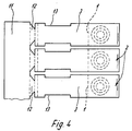
- eine Teildraufsicht auf einen Markierungselementestreifen mit mehreren nebeneinanderliegenden Markierungselementen, letztere in Schließstellung gemäß
Figur 3.
- Figure 1
- a marking element in side view in its open position,
- Figure 2
- the marking element according to Figure 1 in plan view,
- Figure 3
- a side view of a marking element in its closed position, arranged on the upper narrow side of a terminal block,
- Figure 4
- 3 shows a partial top view of a marking element strip with a plurality of marking elements lying next to one another, the latter in the closed position according to FIG. 3.
Das in den Figuren 1 und 2 in der Offenstellung gezeigte Markierungselement hat ein Fußteil 1, mit dem schwenkbeweglich und einstückig über ein als Fimscharnier ausgebildetes Scharnierband 2 ein Bezeichnungsschildteil 3 verbunden ist. Das Fußteil 1 hat Rastfüße 4, mit denen, wie in Figur 3 illustriert, das Fußteil 1 mit den üblichen Rastnuten 5 verrastet werden kann, wie sie in den zugänglichen schmalen Oberseiten der Isolierstoffkörper 6 von Reihenklemmen vorhanden sind. In diese Rastnuten 5 können auch die üblichen kleinen Bezeichnungsträgerelemente eingerastet werden.The marking element shown in FIGS. 1 and 2 in the open position has a
Im dargestellten Ausführungsbeispiel weist das Fußteil 1 des Markierungselementes eine Rastbohrung 7 auf, mit der ein an entsprechender Stelle auf dem Bezeichnungsschildteil 3 vorgesehener Rastzapfen 8 in der Schließstellung des Markierungselementes zusammenwirkt, in der, wie aus Figur 3 ersichtlich ist, das Bezeichnungsschildteil 3 mittels des Filmscharnieres 2 auf das Fußteil 1 herumgeschwenkt ist. Der Rastzapfen 8 tritt dabei in die Rastbohrung 7. In dieser Schließstellung liegt dank der Rastverbindung das Bezeichnungsschildteil des Markierungselementes zuverlässig über der schmalen Oberseite des Isolierstoffkörpers 6 der Reihenklemme und übernimmt hier auch Abdeckfunktion für dort befindliche übliche Zugangsöffnungen für Querverbinderelemente, Betätigungswerkzeuge, Prüfstecker und dergleichen.In the exemplary embodiment shown, the
Zur Erzielung einer besonders sicheren Rastverbindung ist im dargestellten Ausführungsbeispiel auf der Oberseite des Fußteiles 1 ein runder Ansatz 9 vorgesehen, durch den sich die Rastbohrung 7 erstreckt. In dem Bezeichnungsschildteil ist eine runde Aussparung 10 gebildet, von deren Grund der Rastzapfen 8 vorsteht und die in der Schließstellung den Ansatz 9 übergreift.In order to achieve a particularly secure snap-in connection, a round attachment 9 is provided on the top of the
Wie insbesondere aus Figur 4 ersichtlich, jedoch auch in den anderen Figuren illustriert, ist aus Gründen der Herstellung und auch der Handhabung zweckmäßigerweise ein Markierungselementestreifen mit einer Mehrzahl nebeneinander angeordneter derartiger Markierungselemente gebildet. Dabei hängen die nebeneinanderliegenden Markierungselemente mit ihren freien Enden an einem gemeinsamen Querverbindungsstreifen 11. Sie sind daran zweckmäßig über eine Trennstelle 12 angeformt. Der Querverbindungsstreifen 11 bietet die Möglichkeit, eine Mehrzahl derartiger Markierungselemente gleichzeitig auf eine Anreihung von Reihenklemmen zu setzen und auf diesen mittels des Fußteiles 1 zu verrasten. Man kann in so einem Fall den Querverbindungsstreifen an den Markierungselementen belassen und hat die Möglichkeit, die im Sichtbereich liegende Fläche des Querverbindungsstreifens ganz oder teilweise als zusätzliche Bezeichnungsfläche zu nutzen.As can be seen in particular from FIG. 4, but also illustrated in the other figures, for reasons of production and handling, a strip of marking elements is expediently formed with a plurality of such marking elements arranged next to one another. The adjacent marking elements hang with their free ends on a
Es besteht aber auch ohne weiteres die Möglichkeit, im Bedarfsfall einzelne Markierungselemente über die Trennstelle 12 von dem gemeinsamen Querverbindungsstreifen abzutrennen und sie dann einzeln auf die Reihenklemmen aufzusetzen und mit ihnen zu verrasten.However, there is also the possibility, if necessary, of separating individual marking elements from the common cross-connection strip via the separating
Für die Anbringung der eigentlichen Bezeichnungen an dem Bezeichnungsschildteil 3 bestehen die verschiedensten Möglichkeiten. Die in der Schließ- bzw. Gebrauchslage sichtbare Bezeichnungsschildfläche kann unmittelbar mit den Bezeichnungen bedruckt sein. Es ist aber auch ohne weiteres möglich, in dieser Fläche des Bezeichnungsschildteiles 3 die üblichen und bekannten Rastnuten, beispielsweise vergleichbar der Rastnuten 5 (Figur 3) vorzusehen und dann in diese die üblichen kleinen Bezeichnungsträgerstückchen in der jeweils gewünschten Anordnung einzurasten.There are many different options for attaching the actual designations to the
Es ist ferner hervorzuheben, daß die Markierung am Bezeichnungsschildteil 3 durchaus nicht nur auf dessen in der Schließstellung zu sehenden Oberseite erfolgen kann. Insoweit kann durchaus noch die Unterseite benutzt werden. Die Markierungen auf der Unterseite sind naturgemäß nur nach dem Öffnen des Markierungselementes sichtbar. Dieses Öffnen ist in jeder Weise problemlos, wobei durch die unlösbare Verbindung von Bezeichnungsschildteil 3 und Fußteil 1 durch das Filmscharnier 2 das Bezeichnungsschildteil 3 immer an der Klemme gehalten wird. Die Zuordnung der Markierungen zur Klemme bleibt also in jedem Fall bestehen.It should also be emphasized that the marking on the
Wie bereits hervorgehoben, hat insbesondere das Bezeichnungsschildteil 3 des Markierungselementes in der Schließstellung Schutzfunktion. Es kann dabei insbesondere, wie in Figur 3 illustriert, auch die Abdeckung der Querverbindung einer Reihenklemmenanordnung gewährleisten. Um trotz dieser Abdeckfunktion die manchmal für wünschenswert gehaltene Einsehbarkeit des unter dem Bezeichnungssschildteil 3 liegenden Raumes der Reihenklemme sicherzustellen, sind in weiterer zweckmäßiger Ausgestaltung Aussparungen 13 an den Längsseiten des Bezeichnungsschildteiles 3 vorgesehen.As already emphasized, the
Gemäß einer weiteren, bevorzugten Ausführungsform kann das Markierungselement aus zwei verschiedenen Werkstoffen bestehen, die zweckmäßig beim Spritzvorgang unlösbar miteinander verbunden werden. Wie in Figur 1 mit der Trennlinie 14 angedeutet, besteht zweckmäßig das Fußteil 1 mit Scharnierband 2 und ein Teilbereich des Bezeichungsschildteiles 3 aus einem Kunststoff mit hohen Elastizitätswerten. Ein weiterer Bereich des Schildteiles 3, insbesondere dessen Oberseitenbereich, besteht aus einem Kunststoff mit besonders guten Hafteigenschaften gegenüber einem Aufdruck. Dieser Werkstoff ist zweckmäßig auch besonders spröde, um die Abtrennung von dem gemeinsamen Verbinderstreifen zu erleichtern.According to a further preferred embodiment, the marking element can consist of two different materials which are expediently non-detachably connected to one another during the spraying process. As indicated in FIG. 1 with the
Claims (12)
- A marking element for electrical modular terminals, comprising a base portion (1) latchable to designation carrier mountings (5) of the insulating material body (6) of the modular terminal, and a designation plate portion (3) which is pivotably connected to the base portion and which can be mounted on the narrow top side of the modular terminal, wherein the designation plate portion (3) and the base portion (1) are integrally connected together by way of a hinge strip (2), characterised in that the designation plate portion (3) and the base portion (1) have latching means (7, 8) for mutual latching thereof.
- A marking element according to claim 1 characterised in that the hinge strip is in the form of a film hinge (2).
- A marking element according to claim 1 or claim 2 characterised in that provided on the top side of the base portion (1) is a projection (9) through which a latching bore (7) extends to the opposite side of the base portion (1), and that provided on the designation plate portion (3) is a latching peg (8) which co-operates with the latching bore (7) and which projects from the bottom of the recess (10) which in the closed position engages over the projection (9).
- A marking element according to one of the preceding claims characterised in that recesses (13) are provided in the longitudinal sides of the designation plate portion (3).
- A marking element according to one of the preceding claims characterised in that at the top side and/or the underside the designation plate portion (3) is in the form of a designation carrier.
- A marking element according to one of claims 1 to 5 characterised in that at the top side and/or the underside the designation plate portion (3) is provided with receiving means for designation plates.
- A marking element according to one of the preceding claims characterised by a marking element strip in which a plurality of marking elements are moulded in side-by-side relationship with their respective free ends of their designation plate portions (3) integrally by way of a dividing location (12) on to a transverse connecting bar portion (11).
- A marking element according to claim 7 characterised in that the transverse connecting bar portion (11) has one or more designation surfaces.
- A marking element according to one of the preceding claims characterised in that the marking element is formed from different materials.
- A marking element according to claim 9 characterised in that the base portion (1) and the film hinge (2) comprise a plastics material of high elasticity.
- A marking element according to claim 9 characterised in that the designation plate portion at its top side comprises a material with a high level of adhesion relative to an imprint thereon.
- A marking element according to claim 9 characterised in that the outside end of the designation plate portion (3) comprises a brittle material.
Applications Claiming Priority (2)
| Application Number | Priority Date | Filing Date | Title |
|---|---|---|---|
| DE4201217A DE4201217C2 (en) | 1992-01-18 | 1992-01-18 | Marking element for electrical terminal blocks |
| DE4201217 | 1992-01-18 |
Publications (3)
| Publication Number | Publication Date |
|---|---|
| EP0552413A2 EP0552413A2 (en) | 1993-07-28 |
| EP0552413A3 EP0552413A3 (en) | 1994-03-02 |
| EP0552413B1 true EP0552413B1 (en) | 1996-06-19 |
Family
ID=6449761
Family Applications (1)
| Application Number | Title | Priority Date | Filing Date |
|---|---|---|---|
| EP92116510A Expired - Lifetime EP0552413B1 (en) | 1992-01-18 | 1992-09-26 | Marker for electrical terminal blocks |
Country Status (5)
| Country | Link |
|---|---|
| US (1) | US5338224A (en) |
| EP (1) | EP0552413B1 (en) |
| JP (1) | JPH06260224A (en) |
| CA (1) | CA2086988C (en) |
| DE (1) | DE4201217C2 (en) |
Cited By (3)
| Publication number | Priority date | Publication date | Assignee | Title |
|---|---|---|---|---|
| US8857086B2 (en) | 2012-09-12 | 2014-10-14 | Panduit Corp. | Flex mount terminal marker |
| US9058752B2 (en) | 2012-09-12 | 2015-06-16 | Panduit Corp. | Flex mount terminal marker |
| US10062979B2 (en) | 2015-08-21 | 2018-08-28 | Panduit Corp. | Terminal block marker |
Families Citing this family (14)
| Publication number | Priority date | Publication date | Assignee | Title |
|---|---|---|---|---|
| DE9414940U1 (en) * | 1994-09-14 | 1994-11-10 | Siemens Ag | Terminal block with cover |
| DE29510325U1 (en) * | 1995-06-26 | 1996-08-01 | Siemens Ag | Terminal labeling element for an electrical device, and terminal cover or electrical device provided with labeling elements |
| US5741153A (en) * | 1995-07-27 | 1998-04-21 | Ortronics, Inc. | Modular connectors including terminated rear connector designation for insulation displacement connectors |
| GB9626904D0 (en) * | 1996-12-24 | 1997-02-12 | Lloyd Davy Dawn Y | A cover for electrical connectors/accessories |
| DE19722936C1 (en) * | 1997-05-23 | 1998-10-08 | Krone Ag | Protective plug |
| US6140796A (en) * | 1997-08-07 | 2000-10-31 | Martin Safety Products Co. | Battery jump-start safety system and process |
| GB2380869B (en) * | 2001-10-06 | 2005-04-20 | Mayall & Co Ltd | A connector having a label mounting means |
| US20060009068A1 (en) * | 2004-07-06 | 2006-01-12 | Michael Greene | Cable labeling caps |
| NL2011338C2 (en) * | 2013-08-27 | 2015-03-02 | Abb Bv | GROUP CABINET WITH IDENTIFICATION LABEL. |
| DE102014114103B4 (en) | 2014-09-29 | 2022-02-03 | Wago Verwaltungsgesellschaft Mbh | Marking strip and method of marking it |
| EP3435487B1 (en) * | 2017-07-26 | 2021-04-28 | TE Connectivity Services GmbH | Label-holder device for junction block |
| EP3435486B1 (en) * | 2017-07-26 | 2020-08-19 | TE Connectivity Services GmbH | Label-holder device for junction block |
| US10702049B2 (en) * | 2018-08-14 | 2020-07-07 | Hai Pin Tsai | Buckle belt assembly |
| CN117073883B (en) * | 2023-10-16 | 2024-01-30 | 江天科技有限公司 | Intelligent bolt, nut and gasket early warning device |
Family Cites Families (11)
| Publication number | Priority date | Publication date | Assignee | Title |
|---|---|---|---|---|
| US2548104A (en) * | 1948-09-29 | 1951-04-10 | Robert E Frison | Tag and card holder |
| US3416200A (en) * | 1967-03-22 | 1968-12-17 | Scovill Manufacturing Co | Permanently locking snap fastener |
| US3729780A (en) * | 1971-07-08 | 1973-05-01 | R White | Clamp |
| DE2617228C3 (en) * | 1976-04-20 | 1978-12-21 | Siemens Ag, 1000 Berlin Und 8000 Muenchen | End bracket with shield cap |
| CH636481A5 (en) * | 1980-06-13 | 1983-05-31 | Ultra Precision Sa | SUPPORT DEVICE FOR INTEGRATED CIRCUIT. |
| US4441233A (en) * | 1983-01-31 | 1984-04-10 | E. J. Brooks Company | Security seal with weakened portion in stud |
| US4514882A (en) * | 1983-10-26 | 1985-05-07 | Christian Lavielle | Device for retaining in side-by-side relationship flexible tying means such as shoelaces |
| JPH054297Y2 (en) * | 1985-02-07 | 1993-02-02 | ||
| US4637676A (en) * | 1985-05-13 | 1987-01-20 | Allen-Bradley Company | Terminal block marking surface |
| DE3929905C1 (en) * | 1989-09-08 | 1990-10-31 | F. Wieland Elektrische Industrie Gmbh, 8600 Bamberg, De | Terminal strip marking arrangement - has vertical support plates for row of terminals mounted in switch cabinet |
| US5056197A (en) * | 1991-02-25 | 1991-10-15 | Joel Cohen | Clip of extruded plastic material |
-
1992
- 1992-01-18 DE DE4201217A patent/DE4201217C2/en not_active Expired - Lifetime
- 1992-09-26 EP EP92116510A patent/EP0552413B1/en not_active Expired - Lifetime
- 1992-12-28 US US07/997,215 patent/US5338224A/en not_active Expired - Lifetime
-
1993
- 1993-01-08 CA CA002086988A patent/CA2086988C/en not_active Expired - Lifetime
- 1993-01-18 JP JP5005730A patent/JPH06260224A/en active Pending
Cited By (3)
| Publication number | Priority date | Publication date | Assignee | Title |
|---|---|---|---|---|
| US8857086B2 (en) | 2012-09-12 | 2014-10-14 | Panduit Corp. | Flex mount terminal marker |
| US9058752B2 (en) | 2012-09-12 | 2015-06-16 | Panduit Corp. | Flex mount terminal marker |
| US10062979B2 (en) | 2015-08-21 | 2018-08-28 | Panduit Corp. | Terminal block marker |
Also Published As
| Publication number | Publication date |
|---|---|
| EP0552413A3 (en) | 1994-03-02 |
| EP0552413A2 (en) | 1993-07-28 |
| US5338224A (en) | 1994-08-16 |
| JPH06260224A (en) | 1994-09-16 |
| DE4201217C2 (en) | 1993-12-09 |
| DE4201217A1 (en) | 1993-07-22 |
| CA2086988A1 (en) | 1993-07-19 |
| CA2086988C (en) | 2000-04-04 |
Similar Documents
| Publication | Publication Date | Title |
|---|---|---|
| EP0552413B1 (en) | Marker for electrical terminal blocks | |
| CH686325A5 (en) | Electronic module and chip card. | |
| DE2161871A1 (en) | Socket unit for receiving electronic components | |
| EP3631902B1 (en) | Method and device for marking terminal blocks | |
| EP0352347A1 (en) | Electrical connector | |
| EP0115055A2 (en) | Conductor end socket with marking bearer | |
| DE19711128C1 (en) | Distribution board for telecommunications and data technology | |
| DE19755848C2 (en) | Multi-function adapter for a number of busbars in a busbar system | |
| DE3711789C2 (en) | ||
| DE3324652C1 (en) | Terminal block | |
| EP0709817B1 (en) | Marking tag to be fastened to an electrical or electronical component by snap-fitting | |
| EP0216286A2 (en) | Substrate for integrated components | |
| EP0819857B1 (en) | Dowel carrier strip with a plurality of dowels | |
| DE3625986C1 (en) | Marking plate carrier for a plug housing | |
| DE8613221U1 (en) | Plug part of a coupling plug for proximity switches or the like. | |
| DE3507694C1 (en) | Device for marking connections, connecting leads and the like on electrical apparatuses, components and the like | |
| WO1999039404A1 (en) | Support for an electrical contact arrangement | |
| DE3447327A1 (en) | MAGNETIC FIELD DETECTOR | |
| DE931244C (en) | Electrical outlet | |
| DE2319523A1 (en) | SECURITY ARRANGEMENT | |
| DE3744684A1 (en) | Legend plate (label) carrier for a connector housing | |
| EP1002326B1 (en) | Fuse with coding | |
| DE2320867C3 (en) | Distributors for telecommunications, in particular telephone systems | |
| DE3028107C2 (en) | Combinable miniaturized spacer and fastening element for an electrical component | |
| DE3912481C1 (en) |
Legal Events
| Date | Code | Title | Description |
|---|---|---|---|
| PUAI | Public reference made under article 153(3) epc to a published international application that has entered the european phase |
Free format text: ORIGINAL CODE: 0009012 |
|
| AK | Designated contracting states |
Kind code of ref document: A2 Designated state(s): CH FR GB IT LI SE |
|
| PUAL | Search report despatched |
Free format text: ORIGINAL CODE: 0009013 |
|
| AK | Designated contracting states |
Kind code of ref document: A3 Designated state(s): CH FR GB IT LI SE |
|
| 17P | Request for examination filed |
Effective date: 19940129 |
|
| 17Q | First examination report despatched |
Effective date: 19951120 |
|
| GRAH | Despatch of communication of intention to grant a patent |
Free format text: ORIGINAL CODE: EPIDOS IGRA |
|
| ITF | It: translation for a ep patent filed |
Owner name: STUDIO INGG. FISCHETTI & WEBER |
|
| GRAH | Despatch of communication of intention to grant a patent |
Free format text: ORIGINAL CODE: EPIDOS IGRA |
|
| GRAA | (expected) grant |
Free format text: ORIGINAL CODE: 0009210 |
|
| AK | Designated contracting states |
Kind code of ref document: B1 Designated state(s): CH FR GB IT LI SE |
|
| REG | Reference to a national code |
Ref country code: CH Ref legal event code: NV Representative=s name: ISLER & PEDRAZZINI AG |
|
| GBT | Gb: translation of ep patent filed (gb section 77(6)(a)/1977) |
Effective date: 19960723 |
|
| ET | Fr: translation filed | ||
| ET | Fr: translation filed | ||
| PLBE | No opposition filed within time limit |
Free format text: ORIGINAL CODE: 0009261 |
|
| STAA | Information on the status of an ep patent application or granted ep patent |
Free format text: STATUS: NO OPPOSITION FILED WITHIN TIME LIMIT |
|
| 26N | No opposition filed | ||
| REG | Reference to a national code |
Ref country code: GB Ref legal event code: IF02 |
|
| REG | Reference to a national code |
Ref country code: CH Ref legal event code: PCAR Free format text: ISLER & PEDRAZZINI AG;POSTFACH 1772;8027 ZUERICH (CH) |
|
| PGFP | Annual fee paid to national office [announced via postgrant information from national office to epo] |
Ref country code: IT Payment date: 20100927 Year of fee payment: 19 |
|
| PGFP | Annual fee paid to national office [announced via postgrant information from national office to epo] |
Ref country code: CH Payment date: 20110923 Year of fee payment: 20 |
|
| PGFP | Annual fee paid to national office [announced via postgrant information from national office to epo] |
Ref country code: SE Payment date: 20110923 Year of fee payment: 20 Ref country code: GB Payment date: 20110920 Year of fee payment: 20 Ref country code: FR Payment date: 20110928 Year of fee payment: 20 |
|
| REG | Reference to a national code |
Ref country code: CH Ref legal event code: PL |
|
| REG | Reference to a national code |
Ref country code: GB Ref legal event code: PE20 Expiry date: 20120925 |
|
| REG | Reference to a national code |
Ref country code: SE Ref legal event code: EUG |
|
| PG25 | Lapsed in a contracting state [announced via postgrant information from national office to epo] |
Ref country code: GB Free format text: LAPSE BECAUSE OF EXPIRATION OF PROTECTION Effective date: 20120925 |