EP0551421B1 - Sicherheitsspritze mit zurückziehbarer hohlnadel - Google Patents
Sicherheitsspritze mit zurückziehbarer hohlnadel Download PDFInfo
- Publication number
- EP0551421B1 EP0551421B1 EP91919295A EP91919295A EP0551421B1 EP 0551421 B1 EP0551421 B1 EP 0551421B1 EP 91919295 A EP91919295 A EP 91919295A EP 91919295 A EP91919295 A EP 91919295A EP 0551421 B1 EP0551421 B1 EP 0551421B1
- Authority
- EP
- European Patent Office
- Prior art keywords
- barrel
- needle
- plunger
- syringe
- housing
- Prior art date
- Legal status (The legal status is an assumption and is not a legal conclusion. Google has not performed a legal analysis and makes no representation as to the accuracy of the status listed.)
- Expired - Lifetime
Links
Images


Classifications
-
- A—HUMAN NECESSITIES
- A61—MEDICAL OR VETERINARY SCIENCE; HYGIENE
- A61M—DEVICES FOR INTRODUCING MEDIA INTO, OR ONTO, THE BODY; DEVICES FOR TRANSDUCING BODY MEDIA OR FOR TAKING MEDIA FROM THE BODY; DEVICES FOR PRODUCING OR ENDING SLEEP OR STUPOR
- A61M5/00—Devices for bringing media into the body in a subcutaneous, intra-vascular or intramuscular way; Accessories therefor, e.g. filling or cleaning devices, arm-rests
- A61M5/178—Syringes
- A61M5/31—Details
- A61M5/32—Needles; Details of needles pertaining to their connection with syringe or hub; Accessories for bringing the needle into, or holding the needle on, the body; Devices for protection of needles
- A61M5/3205—Apparatus for removing or disposing of used needles or syringes, e.g. containers; Means for protection against accidental injuries from used needles
- A61M5/321—Means for protection against accidental injuries by used needles
- A61M5/322—Retractable needles, i.e. disconnected from and withdrawn into the syringe barrel by the piston
- A61M5/3234—Fully automatic needle retraction, i.e. in which triggering of the needle does not require a deliberate action by the user
-
- A—HUMAN NECESSITIES
- A61—MEDICAL OR VETERINARY SCIENCE; HYGIENE
- A61M—DEVICES FOR INTRODUCING MEDIA INTO, OR ONTO, THE BODY; DEVICES FOR TRANSDUCING BODY MEDIA OR FOR TAKING MEDIA FROM THE BODY; DEVICES FOR PRODUCING OR ENDING SLEEP OR STUPOR
- A61M5/00—Devices for bringing media into the body in a subcutaneous, intra-vascular or intramuscular way; Accessories therefor, e.g. filling or cleaning devices, arm-rests
- A61M5/178—Syringes
- A61M5/31—Details
- A61M5/315—Pistons; Piston-rods; Guiding, blocking or restricting the movement of the rod or piston; Appliances on the rod for facilitating dosing ; Dosing mechanisms
- A61M5/31511—Piston or piston-rod constructions, e.g. connection of piston with piston-rod
- A61M5/31513—Piston constructions to improve sealing or sliding
-
- A—HUMAN NECESSITIES
- A61—MEDICAL OR VETERINARY SCIENCE; HYGIENE
- A61M—DEVICES FOR INTRODUCING MEDIA INTO, OR ONTO, THE BODY; DEVICES FOR TRANSDUCING BODY MEDIA OR FOR TAKING MEDIA FROM THE BODY; DEVICES FOR PRODUCING OR ENDING SLEEP OR STUPOR
- A61M5/00—Devices for bringing media into the body in a subcutaneous, intra-vascular or intramuscular way; Accessories therefor, e.g. filling or cleaning devices, arm-rests
- A61M5/178—Syringes
- A61M5/31—Details
- A61M5/32—Needles; Details of needles pertaining to their connection with syringe or hub; Accessories for bringing the needle into, or holding the needle on, the body; Devices for protection of needles
- A61M5/34—Constructions for connecting the needle, e.g. to syringe nozzle or needle hub
- A61M5/347—Constructions for connecting the needle, e.g. to syringe nozzle or needle hub rotatable, e.g. bayonet or screw
-
- A—HUMAN NECESSITIES
- A61—MEDICAL OR VETERINARY SCIENCE; HYGIENE
- A61M—DEVICES FOR INTRODUCING MEDIA INTO, OR ONTO, THE BODY; DEVICES FOR TRANSDUCING BODY MEDIA OR FOR TAKING MEDIA FROM THE BODY; DEVICES FOR PRODUCING OR ENDING SLEEP OR STUPOR
- A61M5/00—Devices for bringing media into the body in a subcutaneous, intra-vascular or intramuscular way; Accessories therefor, e.g. filling or cleaning devices, arm-rests
- A61M5/50—Devices for bringing media into the body in a subcutaneous, intra-vascular or intramuscular way; Accessories therefor, e.g. filling or cleaning devices, arm-rests having means for preventing re-use, or for indicating if defective, used, tampered with or unsterile
- A61M5/5013—Means for blocking the piston or the fluid passageway to prevent illegal refilling of a syringe
- A61M5/502—Means for blocking the piston or the fluid passageway to prevent illegal refilling of a syringe for blocking the piston
-
- A—HUMAN NECESSITIES
- A61—MEDICAL OR VETERINARY SCIENCE; HYGIENE
- A61M—DEVICES FOR INTRODUCING MEDIA INTO, OR ONTO, THE BODY; DEVICES FOR TRANSDUCING BODY MEDIA OR FOR TAKING MEDIA FROM THE BODY; DEVICES FOR PRODUCING OR ENDING SLEEP OR STUPOR
- A61M5/00—Devices for bringing media into the body in a subcutaneous, intra-vascular or intramuscular way; Accessories therefor, e.g. filling or cleaning devices, arm-rests
- A61M5/50—Devices for bringing media into the body in a subcutaneous, intra-vascular or intramuscular way; Accessories therefor, e.g. filling or cleaning devices, arm-rests having means for preventing re-use, or for indicating if defective, used, tampered with or unsterile
- A61M5/508—Means for preventing re-use by disrupting the piston seal, e.g. by puncturing
Definitions
- the syringe device comprises a hollow plunger which is extendable into a cylindrical barrel thereby forcing fluid from the barrel and through a needle attached to one end of the barrel.
- the hollow plunger is capable of receiving the retractable needle once the plunger is fully extended into the barrel.
- hypodermic syringes are commonly used to deliver fluids from the syringe to one or more internal areas of the patient. Health care professionals which use hypodermic syringes often risk infection if they accidentally are scratched or punctured by the needle after injections are completed. Therefore, contaminated hypodermic needles present a substantial health hazard to anyone who handles or uses a hypodermic needle. Accordingly, there exists a need to protect personnel from accidental skin puncture injuries from such contaminated needles as well as the need to provide a safe and efficient means for disposing of the needles.
- a triggering mechanism which releases the needle from its extended position to a position inside the syringe.
- Typical triggering mechanisms involve activating arms or levers placed on the outside of the syringe. When these external levers are activated, the needle is automatically drawn into the syringe by one or more biasing mechanisms. While external levers having automatic retraction mechanisms provide an easier means for retracting the needle, they are often unduly complicated to both manufacture and operate.
- the trigger mechanisms are often configured at a point distant from the plunger, thereby requiring the operator to move his or her hand from a convenient point on the plunger to a distal trigger location. Further, they may be inadvertently activated if the triggering mechanism is accidentally activated.
- WO 89/00435 discloses a syringe comprising a cylindrical barrel having first and second ends between which fluid is contained in use; a hollow plunger inserted into the first end of the barrel; a hollow needle extending from the second end of the barrel and being fixed to a hub; biasing means within a housing attached to the second end of the barrel for biasing the needle towards the hollow plunger but movement of the needle towards the plunger initially being prevented by engagement of the needle's hub with an end wall of the barrel at the second end thereof; a sealing member attached to one end of the plunger for sliding engagement with the inside of the barrel for driving the fluid from the barrel and through the needle when the plunger is advanced in the barrel in use towards the second end; a tip within the sealing member and arranged, upon completion of the advance of the plunger to drive the fluid from the barrel, to create in the end wall a hole sufficiently large for the needle and the hub to be forced by the biasing means into the plunger; and, according to the present invention, such a syringe is character
- the safety syringe with retractable needle hereof provides convenient retraction of the needle inside the plunger by applying further pressure to the plunger after the plunger is fully extended into the barrel.
- the safety syringe of the present invention is particularly useful for applying one-hand operation wherein a single forward motion upon the plunger causes fluid to be delivered and, after deliver, increased pressure on the plunger causes the needle to be automatically retracted.
- the present invention allows retraction of the needle either while the needle is embedded or withdrawn from the patient.
- the present invention allows withdrawal or harvesting of fluid from a patient and after the fluid is withdrawn and delivered to a suitable container, the present invention can retract the needle to prevent reuse.
- the biasing means may comprise a helically coiled compression spring within the housing which is fitted to the second end of the barrel.
- the housing may include a surface for permanent attachment by means such as sonic welding of the housing onto the distal end of the barrel.
- the housing may alternatively include at least one detent for snap-on fit with at least one detent on the distal end of the barrel.
- the above alternative configurations include, but are not limited to the many various configurations which may be used to attach the housing onto one end of the barrel or for biasing the needle toward the hollow plunger.
- the syringe may include a Luer-Lock arrangement wherein the spring housing is a self-contained unit
- the Luer-Lock spring housing unit comprises a retainer connected to the distal end of the housing.
- the needle is configured to extend axially through the centre of the housing from a connection point on the retainer to a point outside the housing.
- a compressed spring is axially displaced over the needle from a connection point on the retainer to a connection point substantially near the proximal end of the housing.
- the Luer-Lock arrangement provide a retainer within the spring housing as opposed to the threaded, sonic welded and snap-fit arrangements which do not include a retainer on the spring housing.
- the Luer-Lock embodiment advantageously allows the operator quickly to attach or detach an unused needle directly onto the syringe of the present device.
- the needle contained within the Luer-Lock spring housing, is retractable by extending the plunger into the barrel such that when the plunger is fully extended, the cutting tip attached to the distal end of the plunger protrudes through the sealing member and retainer thereby releasing the compressed spring and forcing the needle into the hollow plunger.
- the syringe can be used for delivering fluid to a patient through a needle of a hypodermic syringe and retracting the needle within the syringe after the fluid is delivered.
- the needle which is implanted into the patient.
- the operator applies one-handed force to one end of the plunger to force fluid from the barrel and into the patient.
- the plunger is then fully extended into the barrel to force all the fluid from the barrel.
- the cutting tip extends through the retainer thereby causing the biased needle to be released into the plunger.
- the needle can be retracted into the plunger either while the needle is embedded into the patient or after the needle is withdrawn from the patient. In either case, delivery, as well as retraction, is achieved by a simple one-hand forward pressure upon the plunger.
- the present invention therefore provides an improved device which allows convenient retraction of the needle by forward movement of the plunger and is also easy to manufacture and relatively inexpensive to produce.
- the triggering mechanism for retracting the needle is contained entirely within the syringe and thus does not suffer the disadvantages associated with conventional, external triggering devices.
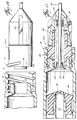
- Fig. 1 illustrates safety syringe 10 including a cylindrical barrel 12 having a distal end 14 and proximal end 16.
- Proximal end 16 is generally open thereby allowing a plunger 18 to be inserted within barrel 12.
- Proximal end 16 may include a flange 20 upon which the operator's fingers may be secured when actuating plunger 18.
- the barrel's distal end 14 is configured to receive a spring housing 22.
- Housing 22 functions to contain one end of a spring 24 which becomes compressed against distal end 14 when housing 22 is attached to end 14.
- Spring distal end 26 is securely held upon flange 28 of spring housing 22.
- spring 24 slides over needle 30 and is compressed around 30 between housing flange 28 and a portion of the distal end 14, or retainer 32.
- spring housing 22 functions to provide a biasing force against retainer 32 when housing 22 is attached to barrel 12. Compression force on spring 24 causes retainer 32 and attached needle 30 to be biased toward plunger 18.
- Plunger 18 is a hollow cylindrical member having a distal end 34 and a proximal end 36. Proximal end 36 is closed and, may contain a plunger flange 38 to provide a convenient pressure point to accommodate an operator's finger. Configured at plunger distal end 34 is a shortened cylindrical section 40. Section 40 is hollow having an inner diameter less than the inner diameter of plunger 18. Also, the outer diameter of section 40 is preferably less than the outer diameter of plunger 18. At the distal end of section 40, between the outer diameter and inner diameter of section 40, is a cutting tip 42 generally configured as a cylindrical knife.
- Sealing member 44 is made of a penetrable soft, flexible rubber-like material or plastic material having at least one radially extending protrusion having an outer diameter which sliding engages with the inner diameter of barrel 12. Member 44, while allowing sliding engagement, substantially prevents fluid leaking from the distal side to the proximal side of member 44. Thus, member 44 provides a substantially fluid-type sealing engagement with the inner diameter of barrel 12 such that fluid in chamber 46 is forced through needle 30 by forward movement of plunger 18.
- Member 44 is preferably made of a rubber or elastomer material, but can be of any material which provides substantial fluid-type sliding engagement with the inner diameter of barrel 12. Further, barrel 12 is of any material which has a substantially smooth inner diameter and therefore may include, but is not limited to plastic, glass, etc.
- Fig. 2 illustrates the functionality of the retractable needle syringe of the present invention.
- plunger distal end 34 As plunger distal end 34 is moved from barrel proximal end 16 to barrel distal end 14, fluid is forced from chamber 46 through needle 30. After all the fluid is withdrawn from syringe 10, and the distal end of member 44 is flush with barrel distal end 14, additional force on plunger proximal end 36 causes cutting tip 42 to penetrate through sealing member 44 and retainer 32. Once retainer 32 is severed from barrel distal end 14 by cutting tip 42, compressed spring 24 forces retainer 32 and attached needle 30 into hollow plunger 18. A portion of the soft sealing member 44 which is cut by cutting tip 42 and displaced by spring 24 is shown in Fig. 2 as 44A.
- Portion 44A is forced into plunger 18 by the releasing force of spring 24.
- the cylindrical knife of tip 42 also cuts through a thin tab or web member 48 thereby releasing retainer 32 and attached needle 30 into plunger 18.
- Tab 48 is constructed of any material which is easily penetrable by tip 42 but remains rigid until penetration. Tab 48 thereby may be constructed of plastic, thin metal, thread or the like. It is understood, however, that tab 48 is not limited to any particular construction as long as the construction chosen performs the desired function as outlined herein.
- shortened section 40 is cylindrical and tip 42 is substantially circular, both having radial dimensions which are substantially equal to and accommodated by cavity 50.
- Cavity 50 is preferably a partially cylindrical shaped bore which extends axially along spring housing 22. Cavity 50 also accommodates spring 24 between spring housing flange 28 and retainer 32.
- the force of coil spring 24 causes portion 44A and retainer 32 to travel smoothly through the hollow section 40.
- the initial force of compressed spring 24 easily moves portion 44A and retainer 32 within the smaller diameter section 40.
- the larger inner diameter hollow plunger easily accommodates the retracted components.
- shortened section 40 is long enough to align with and penetrate into cavity 50 but is not too long to cause the retracted components to bind or become plugged inside section 40. Any length which is appropriate for both purposes may be used.
- Figs. 3-5 illustrate, in an enlarged view, the release mechanism of the present invention. Shown in Fig. 3 is sealing member 44 not yet fully engaged with barrel distal end 14. Tabs 48 and cutting tip 42 are shown axially aligned with one another. Spring 24 is compressed against retainer 32 to provide biasing force of attached needle 30 through hollow cylindrical section 40.
- Fig. 4 illustrates plunger 18 being forced further into barrel 12 such that sealing member 44 abuts against barrel distal end 14. Accordingly, all the fluid is forced from chamber 46 through hollow needle 30 thereby evacuating all fluid from the syringe.
- female detents 52 on the inner diameter of member 44 release male detents 54 on the outer diameter of section 40 so that section 40 can extend within cavity 50 while member 44 remains in barrel 12.
- Female and male detents 52 and 54 function to maintain member 44 configure about the distal end of section 40. As the distal end of section 40 or cutting tip 42 traverses member 44 and tab 48 the mating of female and male detents 52 and 54 is broken as shown in Figs. 4 and 5. Once cutting tip 42 extends into cavity 50, female and male detents 52 and 54 separate thereby allowing member 44 to remain stationary within barrel 12 and secures against distal end 14. Further, member 44 also provides a stop means, wherein edge 56 of plunger 18 comes to rest against member 44 when section 40 is fully extended in cavity 50. Edge 56 provides palpable indicia of the fullest extent upon which plunger 18 can be extended. Fig. 5 illustrates this point.
- edge 56 is configured in such a way as to give section 40 sufficient axial length to allow the retractable components to extend through section 40 without becoming jammed or bound therein.
- Figs. 3-6 illustrate one embodiment of cutting tip 42, wherein the tip comprises a cylindrical knife edge for piercing member 44 and tab 48 simultaneously around the entire circumference of the knife edge.
- a beveled cutting tip 42A shown in Figs. 7-9, to pierce one portion of member 44 and tab 48 prior to other portions.
- a beveled tip 42A may allow for easier piercing and penetration of member 44 and tab 48. It is important to note, however, that either embodiment shown in Fig. 6 or Fig. 7 for cutting tip 42 can be used, or other embodiments can be used, as long as the basic function remains, namely that member 44 and tab 48 are cut cleanly and easily leaving a smooth outer surface for easy deployment through the inner diameter surface of section 40 and plunger 18.
- Figs. 4, 6 and 7 also show various embodiments for attaching spring housing 22 to barrel distal end 14.
- Figs. 1-5 illustrate a snap fit configuration between housing 22 and barrel distal end 14. At least one bump, protrusion, tab or detent 58 is arranged on the outer surface of barrel distal end 14. Bump 58 is arranged to receive a cavity or recess 60 within housing 22 when housing 22 is axially displaced over and onto distal end 14. The mating of recess 60 and bump 58 provides secure attachment means between housing 22 and distal end 14. Further, snap-fit arrangement of Figs. 1-5 allows quick axial compression of spring 24 about needle 30.
- Threads 62 placed on distal end 14 can be used to mate with threads placed on the proximal end of housing 22. Threaded mating occurs by first placing the spring attached to housing 22 over needle 30 attached to distal end 14. Second, housing 22 is rotatably inserted onto distal end 14 via mating threads therebetween. As housing 22 is brought in closer contact to distal end 14, spring 24 is compressed thereby providing biasing force against retainer 32 and attached needle 30 toward plunger 18.
- Fig. 7 illustrates another embodiment for attaching housing 22 to barrel distal end 14.
- Housing 22 can be securely fixed to distal end 14 by sonically welding abutting radial surface 64.
- Housing 22 is axially slid over distal end 14 causing spring 24 to become compressed against retainer 32.
- sonic welds are applied to securely affix abutting surfaces 64 between housing 22 and distal end 14.
- small recesses 49 which define a thinner dimension in tab 48 so as to ensure easy and predictable tear or cutting of tab 48 by cutting tip 42 or beveled cutting tip 42a.
- FIGs. 6-8 illustrate various means by which sealing member 44 are, or are not, coupled to section 40.
- Member 44 of Fig. 6 can be simply placed over the distal end of section 40 and not secured thereto. Or, member 44 may be glued to section 40 such that the intrigity of the glue is broken when section 40 extends partially within cavity 50.
- Fig. 7 illustrates that the section 40 and member 44 are coupled by female and male detents 52 and 54 described above.
- Fig. 8 illustrates member 44 being secured to section 40 via a catch mechanism or detents 66 distal from section 40. Catch 66 is arranged between member 44 and a radially extending section 68.
- Fig. 9 illustrates the securing embodiment of Fig. 8 when plunger 18 is fully driven into barrel 12.
- catch 66 releases member 44 from its secured position on section 40.
- member 44 is driven from the distal end of section 40 toward the proximal end as plunger 18 is fully driven into barrel 12.
- Plunger 18 is extended into barrel 12 until radially extending lip 70 comes to rest against the inner surface of barrel distal end 14.
- Figs. 3-9 show many embodiments for axially displacing member 44 on section 40, it is important to note that there are numerous other types of configurations which can be achieved without departing from the invention.
- any form of attachment which provides axial displacement of member 44 is envisioned by the inventors and accordingly, fall within the present invention's scope.
- any form of embodiment which allows palpable feedback to the operator of when tip 42 is fully extended is also included in this application.
- the embodiments shown in Figs. 3-9 serve only as examples of many different ways of achieving the same function with one example differing only in terms of ease of manufacture from that of another.
- Figs. 10 and 11 show another embodiment by which a self-contained spring housing 22A is secured via a Luer-Lock arrangement with barrel distal end 14.
- the Luer-lock arrangement allows spring housing 22A to contain needle 30 and retainer 32.
- Spring housing 22A is rotatably attached to distal end 14 by engaging male threads 71 within female threads 72. As housing 22A is drawn against distal end 14, the outer diameter of cylindrical opening 74 sealingly abuts against the inner diameter of opening 76.
- spring housing 22A includes a forward and aft section 78 and 80, respectively.
- Aft section 80 comprises needle 30 and retainer 32 attached to one end and forward section 78 attached to the other end.
- Forward section 78 comprises spring 24 attached to spring housing flange 28.
- spring 24 is displaced over needle 30 and compressed against retainer 32 to provide biasing force of retainer 32 toward plunger 18.
- forward section 78 can be attached to aft section 80 by any of the various means used herein, including, but not limited to, snap-on, sonic weld, threads, etc.
- a slit or groove 82 can be placed on the outer surface of forward section 78 to facilitate screw-on movement of forward section 78 onto aft section 80. Still further, cutting tip 42, sealing member 44 and section 40 can be configured in any way which allows penetration through member 44 and tab 48 while allowing member 44 to become axially displaced along section 40.
- FIG. 12 Illustrated in Fig. 12 is another embodiment showing Luer-Lok mating of syringe barrel 12 to a spring housing 22B.
- Spring housing 22B unlike spring housing 22A, is designed having a bore 51 extending from the distal end of spring housing 22B to retainer 32. Placed over needle 30 and within bore 51 is spring 24.
- plug 53 is dimensioned to engage between the walls of bore 51 and outer surface of needle 30.
- Plug 53 is preferably a rigid member comprising a plastic material which can traverse opening 55 to snap-fit reside in its illustrated position. Plug 53 is of sufficient strength to retain compressive force of spring 24 when fully inserted in its snap-fit position.
- Plug 53 allows spring housing 22B to be configured onto barrel 12 which is of a size and shape that can be made standard in the industry. Applicant postulates other ways to retain spring 24 by such means as a cotter pin, etc., however, other such means fall within the spirit of this invention.
- Configured at the proximal end of spring housing 22B is a flange or a set of at least two protrusions 73 which can be rotatably received in distal end 14 similar to a standard Luer-Lok mating scheme.
- a guiding member 84 contained within cutting tip 42.
- Member 84 is a unitary part of member 44 and functions to maintain correct alignment of cutting tip 42 in relation to the inner diameter of barrel 12 so that cutting tip 42 is in relatively precise alignment with tab 48 as tip 42 is pushed down barrel 12.
- an edge 86 which pushes against a portion of member 44 as plunger 18 is extended into barrel 12. When cutting tip traverses tab 48 and protrudes into bore 51, edge 86 causes member 44 to axially compress and radially expand.
- Spring 24, compressed between plug 53 and retainer 32, is released as shown in Fig. 13 thereby forcing needle 30 into hollow plunger 18.
- a retaining recess 88 may be configured on barrel flange 20 to retain radially extending flange 38 when plunger 18 is fully extended. As shown in Fig. 13, when plunger 18 is fully extended, flange 38 causes flange 20 to radially flex outward thus accommodating flange 38 within recess 88. Further, member 84 is dimensioned to easily slide within plunger 18 cavity without becoming constricted therein once plunger 18 is fully extended and needle 30 is retracted.
- Figs. 10-13 illustrate the numerous possibilities available in designing and manufacturing an uncomplicated and relatively inexpensive syringe of the present invention.
- a Luer-Lock self-contained spring housing 22A or 22B is preferred in many medical applications and is advantageous when using syringes of varying capacities with standard needles.
- needles of various lengths or gauges can be also attached to barrels of varying capacities. Therefore, Luer-Lock arrangements have become very popular in recent years. Accordingly, Figs. 10-13 take advantage of the Luer-Lock convenience in adapting the Luer-Lock system to the present invention.
- the present invention provides an improved safety syringe with a triggering mechanism internal to the syringe for allowing automatic retraction of the needle into the plunger by a simple and continuous forward motion of the plunger into the barrel.
- Palpable indicia is provided internal to the syringe for signalling when member 44 abuts against the distal end 14 and additional palpable indicia is provided for signalling when cutting tip 42 is fully extended into cavity 50.
- the safety syringe with retractable needle of the present invention is therefore capable of delivering fluid to a patient and subsequently retracting the needle within the syringe after the fluid is delivered.
- a non-reusable syringe 10 of the present invention provides the advantage of not allowing reoccurring use of a contaminated needle.
- cutting tip 42 can be configured in any fashion beyond a cylindrical knife or beveled knife described herein as long as the desired function is obtained.
- member 44 can be axially displaced on section 40 using means other than glue, detents or, as pointed out above, can be simply placed over tip 42 and not secured whatsoever.
- tab 48 can be described in any format which allows retention of compressed spring 24 but can be rapidly and easily penetrated by cutting tip 42.
- spring housing 22 can be secured to distal end 14 by any means which provides compression of spring 24 while preventing substantial movement of needle 33.
- Luer-Lock arrangement can be of a self-contained unitary body or, as shown in Figs. 10 and 11, have separable forward and aft sections for accessing spring 24. It is certainly possible that spring housing 22A can be manufactured as a unitary body with needle 30, spring 24 and retainer 48 contained and sealed therein.
Claims (12)
- Spritze (10) mit einem zylindrischen Behälter (12), der ein erstes Ende (16) und ein zweites Ende (14) aufweist, zwischen denen bei der Benutzung ein Fluid enthalten ist; einem holen Kolben (18), der in das erste Ende (16) des Behälters (12) eingeführt ist; einer hohlen Nadel (30), die aus dem zweiten Ende (14) des Behälters (12) herausragt und an einer Nabe (32) befestigt ist; einem Vorspannungsmittel (24) in einem Gehäuse (22), das am zweiten Ende (14) des Behälters angebracht ist, um die Nadel (13) in Richtung auf den hohlen Kolben (18) vorzuspannen, wobei jedoch eine Bewegung der Nadel in Richtung auf den Kolben anfänglich durch Anlage der Nadel-Nabe (32) an einer Endwand (48) des Behälters an seinem zweiten Ende verhindert ist; einem Dichtungselement (44), das am einen Ende des Kolbens (18) angebracht ist, so daß es gleitend an der Innenseite des Behälters anliegt, um das Fluid aus dem Behälter und durch die Nadel hindurch herauszudrücken, wenn der Kolben in dem Behälter bei der Benutzung in Richtung auf das zweite Ende vorgeschoben wird; und eine innerhalb des Dichtungselements (44) angeordnete und so ausgebildete Spitze (42), daß sie am Ende des Vorschubs des Kolbens, um das Fluid aus dem Behälter herauszudrücken, in der Endwand (48) ein so großes Loch ausbildet, daß es ausreicht, die Nadel und die Nabe durch das Vorspannungsmittel in den Kolben zu drücken, dadurch gekennzeichnet, daß die Endwand (48) einteilig mit der Nabe (32) ausgebildet ist, so daß sie eine feste Barriere zwischen dem Inneren (46) des Behälters und dem Inneren (50) des Gehäuses (22) bildet; und daß die Spitze eine Schneidspitze (42) ist, die so ausgebildet ist, daß sie das Dichtungselement (44) und die Endwand (48) um die Nadel herum durchschneidet, um das Loch zu bilden.
- Spritze nach Anspruch 1, bei der das Vorspannungsmittel eine schraubenlinienförmig gewickelte Druckfeder (24) in dem Gehäuse (22) aufweist, das am zweiten Ende des Behälters (12) angebracht ist.
- Spritze nach Anspruch 2, bei der das Gehäuse (22) auf das zweite Ende (14) des Behälters (12) geschraubt ist.
- Spritze nach Anspruch 2, bei der das Gehäuse (22) mit dem zweiten Ende (14) des Behälters (12) durch eine Luer-Verriegelung verbunden ist.
- Spritze nach Anspruch 2, bei der das Gehäuse (22) durch Ultraschallschweißung mit dem zweiten Ende (14) des Behälters (12) verbunden ist.
- Spritze nach Anspruch 2, bei der das Gehäuse (22) am zweiten Ende (14) des Behälters (12) durch eine auf der Innenseite des Gehäuses ausgebildete Verzahnung (58) befestigt ist, die über eine komplementäre Verzahnung (60) auf der Außenseite des zweiten Ende des Behälters im Schnappsitz aufgebracht ist.
- Spritze nach einem der Ansprüche 2 bis 8, bei der die Feder (24) an der Endwand (32, 48) um die Nadel (30) herum anliegt, jedoch radial innerhalb der Stelle, wo die Wand durch die Schneidspitze (42) durchschnitten wird.
- Spritze nach einem der vorstehenden Ansprüche, bei der die Endwand einen dünnen Membranteil (48) aufweist, der durch die Schneidspitze (42) zu durchschneiden ist.
- Spritze nach einem der vorstehenden Ansprüche, bei der Schneidspitze (42) ein abgeschrägtes Messer ist.
- Spritze nach einem der vorstehenden Ansprüche, die ferner ein Mittel (38, 88) zum Zurückhalten des Kolbens (18) im Behälter (12), nachdem die Nadel (30) in den Kolben gedrückt worden ist, aufweist.
- Spritze nach Anspruch 9, bei der das Zurückhaltungsmittel einen Flansch (38), der mit dem proximalen Ende (36) des Kolbens (18) verbunden ist, und eine Vertiefung (88) am proximalen Ende (16) des Behälters (12) zum Zurückhalten des Flansches (38), wenn der Kolben (18) vollständig in den Behälter (12) ragt, aufweist.
- Spritze nach einem der vorstehenden Ansprüche, bei der das Dichtungselement (44) ein weiches gummiartiges Material ist, das in dem Behälter (12) verschiebbar ist, während es weiterhin dichtend an der Innenseite des Behälters (12) anliegt.
Applications Claiming Priority (3)
| Application Number | Priority Date | Filing Date | Title |
|---|---|---|---|
| US07/592,504 US5053010A (en) | 1990-10-03 | 1990-10-03 | Safety syringe with retractable needle |
| US592504 | 1990-10-03 | ||
| PCT/US1991/007199 WO1992005818A1 (en) | 1990-10-03 | 1991-09-27 | Safety syringe with retractable needle |
Publications (2)
| Publication Number | Publication Date |
|---|---|
| EP0551421A1 EP0551421A1 (de) | 1993-07-21 |
| EP0551421B1 true EP0551421B1 (de) | 1995-05-24 |
Family
ID=24370940
Family Applications (1)
| Application Number | Title | Priority Date | Filing Date |
|---|---|---|---|
| EP91919295A Expired - Lifetime EP0551421B1 (de) | 1990-10-03 | 1991-09-27 | Sicherheitsspritze mit zurückziehbarer hohlnadel |
Country Status (11)
| Country | Link |
|---|---|
| US (1) | US5053010A (de) |
| EP (1) | EP0551421B1 (de) |
| JP (1) | JP3217780B2 (de) |
| AT (1) | ATE122904T1 (de) |
| AU (1) | AU8662491A (de) |
| CA (1) | CA2093227C (de) |
| DE (1) | DE69110050T2 (de) |
| DK (1) | DK0551421T3 (de) |
| ES (1) | ES2074286T3 (de) |
| GR (1) | GR3017071T3 (de) |
| WO (1) | WO1992005818A1 (de) |
Families Citing this family (114)
| Publication number | Priority date | Publication date | Assignee | Title |
|---|---|---|---|---|
| EP0482060A1 (de) * | 1989-07-11 | 1992-04-29 | WILLIAMS, Graham Hugh | Wegwerfbare hypodermische spritze mit einziehbarer nadel |
| US5407431A (en) | 1989-07-11 | 1995-04-18 | Med-Design Inc. | Intravenous catheter insertion device with retractable needle |
| US6096005A (en) | 1989-07-11 | 2000-08-01 | Mdc Investment Holdings, Inc. | Retractable needle medical devices |
| US5188599A (en) * | 1989-07-11 | 1993-02-23 | Med-Design, Inc. | Retractable needle system |
| IT219694Z2 (it) * | 1990-05-25 | 1993-04-26 | Habley Medical Technology Corp | Siringa di sicurezza, monouso |
| EP0515766B1 (de) * | 1991-05-29 | 1994-08-24 | Paolo Caselli | Spritze mit Vorrichtung zum selbsttätigen Klemmen der Nadel und mit Mittel zum Einziehen der Nadel in die Spritze am Ende einer Einspritzung |
| US5211629A (en) * | 1991-12-23 | 1993-05-18 | Pressly William B S | Safety syringe |
| US5613952A (en) | 1991-12-23 | 1997-03-25 | Syringe Develpoment Partners | Safety syringe |
| ITMI920710A1 (it) * | 1992-03-25 | 1993-09-27 | Federico Demetrio | Siringa di sicurezza con ago retrattile dopo l'uso in modo da evitare il riutilizzo della siringa e la diffusione di malattie contagiose per |
| US5180370A (en) * | 1992-05-18 | 1993-01-19 | Gillespie Elgene R | Safety hypodermic syringe with retractable needle |
| AU5016893A (en) * | 1992-08-17 | 1994-03-15 | Edward F. Allard | Method and apparatus for a retracting needle |
| ES2054589B1 (es) * | 1993-01-27 | 1995-03-01 | Mulleras Vicente Montesinos | Jeringuilla retyractil autodestruible. |
| US5344403A (en) * | 1993-06-09 | 1994-09-06 | Rahnfong Lee | Simple retractable safety syringe |
| US5325857A (en) * | 1993-07-09 | 1994-07-05 | Hossein Nabai | Skin biopsy device and method |
| US5385551A (en) * | 1993-09-22 | 1995-01-31 | Shaw; Thomas J. | Nonreusable medical device with front retraction |
| US5573510A (en) * | 1994-02-28 | 1996-11-12 | Isaacson; Dennis R. | Safety intravenous catheter assembly with automatically retractable needle |
| US5389076A (en) * | 1994-04-05 | 1995-02-14 | Shaw; Thomas J. | Single use medical device with retraction mechanism |
| NL9401003A (nl) * | 1994-06-20 | 1996-02-01 | Michael Hendrik Blommaert | Injectienaald. |
| US5632733A (en) * | 1995-05-11 | 1997-05-27 | Shaw; Thomas J. | Tamperproof retractable syringe |
| US6090077A (en) * | 1995-05-11 | 2000-07-18 | Shaw; Thomas J. | Syringe plunger assembly and barrel |
| US5578011A (en) * | 1995-05-11 | 1996-11-26 | Shaw; Thomas J. | Tamperproof retractable syringe |
| US5709667A (en) * | 1995-05-17 | 1998-01-20 | Carilli; Brian D. | Hypodermic needle protection system |
| US5601534A (en) * | 1995-06-07 | 1997-02-11 | The University Of Memphis | Disposable hypodermic syringe and needle combination |
| AU6120296A (en) * | 1995-07-06 | 1997-02-05 | H. Weidmann Ag | Automatic cannula withdrawing device for injection syringes |
| US7300416B2 (en) * | 1995-08-22 | 2007-11-27 | Specialized Health Products International | Pre-filled retractable needle injection ampoules |
| US5769822A (en) * | 1996-09-13 | 1998-06-23 | Mcgary; R. Kern | Non-reusable retractable safety syringe |
| US5919166A (en) * | 1996-09-13 | 1999-07-06 | Mcgary; R. Kern | Non-reusable retractable safety syringe |
| US5800395A (en) | 1996-12-05 | 1998-09-01 | Mdc Investment Holdings, Inc. | Medical device with retractable needle |
| AU4293697A (en) | 1996-12-23 | 1998-07-17 | H. Weidmann Ag | Cannula for medical syringes |
| NO975315D0 (no) * | 1997-01-09 | 1997-11-19 | Medsafe As | Sikkerhetsspröyte med ekspanderende element |
| US5885257A (en) * | 1997-03-18 | 1999-03-23 | Badger; Peter | Spring loaded automatic retractable needle syringe |
| US5810775A (en) | 1997-05-23 | 1998-09-22 | Shaw; Thomas J. | Cap operated retractable medical device |
| US6039713A (en) * | 1997-08-28 | 2000-03-21 | Mdc Investment Holdings, Inc. | Pre-filled retractable needle injection device |
| US6569115B1 (en) * | 1997-08-28 | 2003-05-27 | Mdc Investment Holdings, Inc. | Pre-filled retractable needle injection device |
| US6015438A (en) * | 1997-11-14 | 2000-01-18 | Retractable Technologies Inc. | Full displacement retractable syringe |
| US5935104A (en) * | 1998-08-21 | 1999-08-10 | Safety Medical Manufacturing, Incorporated | Safety medical syringe with retractable needle |
| US6958055B2 (en) | 1998-09-04 | 2005-10-25 | Nmt Group Plc | Retractable needle syringe including a sheath and an intravenous adapter |
| GB2359754B (en) | 2000-03-03 | 2004-04-28 | Nmt Group Plc | Needle sheath |
| US6036674A (en) * | 1998-12-18 | 2000-03-14 | Becton Dickinson And Company | Retracting needle syringe |
| US6010486A (en) * | 1998-12-18 | 2000-01-04 | Becton Dickinson And Company | Retracting needle syringe |
| US6221052B1 (en) | 1998-12-18 | 2001-04-24 | Becton, Dickinson And Company | Retracting needle syringe |
| US6517516B1 (en) | 1999-10-15 | 2003-02-11 | Becton Dickinson And Company | Method of making a retracting needle syringe |
| US6368303B1 (en) | 1999-10-15 | 2002-04-09 | Becton, Dickinson And Company | Retracting needle syringe |
| US6840291B2 (en) * | 1999-10-15 | 2005-01-11 | Becton Dickinson And Company | Attachment for a medical device |
| JP4295821B2 (ja) | 1999-11-29 | 2009-07-15 | エム ディー シー インベストメント ホールディングス インコーポレイテッド | 安全針アセンブリと医療用機器との組み合せ |
| WO2001045776A1 (en) * | 1999-12-07 | 2001-06-28 | Mdc Investment Holdings, Inc. | Safety needle medical bearing devices |
| NO312013B1 (no) * | 1999-12-23 | 2002-03-04 | Syringus As | Kanyletilbaketrekkingsmekanisme, kanyleholder og injeksjonsspröyte |
| CA2320783C (en) * | 2000-01-04 | 2008-04-01 | Becton, Dickinson And Company | Retracting needle syringe |
| AU723060B3 (en) * | 2000-02-22 | 2000-08-17 | Occupational & Medical Innovations Ltd | A single use syringe |
| US6530903B2 (en) | 2000-02-24 | 2003-03-11 | Xiping Wang | Safety syringe |
| AU2001243420A1 (en) * | 2000-03-06 | 2001-09-17 | Mdc Investment Holdings, Inc. | Hypodermic syringe with retractable needle |
| US6183440B1 (en) * | 2000-05-25 | 2001-02-06 | Becton, Dickinson And Company | Hypodermic syringe having a selectively retractable needle |
| NO312059B1 (no) * | 2000-06-23 | 2002-03-11 | Syringus As | En kanyletildekkingsmekanisme, en kanyleholder og en injeksjonsspröyte |
| US6599268B1 (en) | 2000-06-27 | 2003-07-29 | Becton Dickinson And Company | Hypodermic syringe with a selectively retractable needle |
| US6585690B1 (en) * | 2000-06-29 | 2003-07-01 | Becton Dickinson And Company | Hypodermic syringe with selectivity retractable needle |
| AUPQ864900A0 (en) * | 2000-07-10 | 2000-08-03 | Carmona, John Francisco | A syringe |
| US6432087B1 (en) | 2000-07-31 | 2002-08-13 | Becton, Dickinson And Company | Hypodermic syringe with selectively retractable needle |
| US6572584B1 (en) | 2000-08-07 | 2003-06-03 | Retractable Technologies, Inc. | Retractable syringe with reduced retraction force |
| US6558357B1 (en) | 2000-08-30 | 2003-05-06 | Becton Dickinson And Company | Hypodermic syringe with selectively retractable needle |
| US6413237B1 (en) | 2000-08-31 | 2002-07-02 | Becton, Dickinson And Company | Hypodermic syringe with selectively retractable needle |
| US6409701B1 (en) | 2000-09-29 | 2002-06-25 | Becton, Dickinson And Company | Hypodermic syringe with selectively retractable needle |
| AUPR373001A0 (en) * | 2001-03-14 | 2001-04-12 | Glenord Pty Ltd | Improved non-reusable syringe |
| DE20210394U1 (de) | 2002-07-04 | 2002-09-12 | Braun Melsungen Ag | Kathetereinführvorrichtung |
| GB0222166D0 (en) * | 2002-09-25 | 2002-10-30 | Nmt Group Plc | Needle unit |
| US20040064107A1 (en) * | 2002-09-27 | 2004-04-01 | Pi-Chang Lo | Locking design for a needle head |
| US20040116854A1 (en) * | 2002-12-12 | 2004-06-17 | Abulhaj Ramzi F. | Syringe retractable needle and method |
| DE20303231U1 (de) * | 2003-02-27 | 2003-04-30 | Braun Melsungen Ag | Spritzenzylinder mit Kanülenaufsatz |
| US7285110B2 (en) | 2003-06-10 | 2007-10-23 | P. Rowan Smith, Jr. | Retractable hypodermic safety syringe |
| IL157981A (en) | 2003-09-17 | 2014-01-30 | Elcam Medical Agricultural Cooperative Ass Ltd | Auto injector |
| US8673021B2 (en) | 2003-11-26 | 2014-03-18 | Depuy Mitek, Llc | Arthroscopic tissue scaffold delivery device |
| US7604613B2 (en) * | 2004-01-20 | 2009-10-20 | Beckton, Dickinson And Company | Syringe having a retractable needle |
| IL160891A0 (en) | 2004-03-16 | 2004-08-31 | Auto-mix needle | |
| US7465294B1 (en) * | 2004-05-19 | 2008-12-16 | Roman Vladimirsky | Retractable hypodermic needle |
| US7811259B2 (en) | 2004-09-03 | 2010-10-12 | L.O.M. Laboratories Inc. | Single-use pneumatic safety syringe providing gas-driven needle retraction |
| CN102247635B (zh) | 2004-10-14 | 2012-11-21 | 米德兰医药设备控股公司 | 具有可缩回针头的安全医用注射器 |
| FR2885071B1 (fr) * | 2005-04-28 | 2010-02-12 | Becton Dickinson France | Procede d'identification d'un contenant et/ou d'un article fini obtenu a partir dudit contenant, en particulier a usage medical |
| TWI294782B (en) * | 2006-01-27 | 2008-03-21 | Bencha Internat Group Inc | Medically safety injector with a collapsable plunger combination thereof |
| US7846135B2 (en) | 2006-02-24 | 2010-12-07 | Midland Medical Holding LLC | Retractable needle syringe with needle trap |
| CN100563740C (zh) * | 2006-09-28 | 2009-12-02 | 明辰股份有限公司 | 医疗药物安全注射装置及用于医疗药物注射的推杆组合件 |
| ITMI20062190A1 (it) * | 2006-11-15 | 2008-05-16 | Amendola Carlo | Siringa monouso di tipo perfezionato |
| US8088110B2 (en) * | 2006-11-17 | 2012-01-03 | Bencha International Group Inc. | Automatically retractable safety injector for non-liquid material |
| EP2129419A2 (de) * | 2007-03-21 | 2009-12-09 | Midland Medical Devices Holdings, LLC | Medizinische sicherheitsspritze mit einziehbarer nadel und einem in einem zylinder aufgenommenen kolben |
| KR101509270B1 (ko) * | 2007-06-12 | 2015-04-07 | 백톤 디킨슨 앤드 컴퍼니 | 불능화 기구를 구비한 주사기 |
| US8361018B2 (en) | 2007-06-12 | 2013-01-29 | Becton, Dickinson And Company | Syringe with disabling mechanism |
| GB0808474D0 (en) * | 2008-05-10 | 2008-06-18 | Karolia Ebrahim | Auto retract syringe |
| WO2009148969A1 (en) | 2008-06-02 | 2009-12-10 | Sta-Med, Llc | Needle cover assembly for a syringe |
| US8167820B2 (en) * | 2009-03-20 | 2012-05-01 | Mahurkar Sakharam D | Retractable needle-safety blood sampling device |
| IL197761A0 (en) * | 2009-03-23 | 2009-12-24 | Moshe Zalsman | Capsule for mixing together two flowable materials, and kits including such capsules, particularly useful in dentistry |
| US20110125130A1 (en) * | 2009-04-08 | 2011-05-26 | Stat Medical Devices, Inc. | Retractable needle assembly and syringe utilizing the same |
| US9480799B2 (en) * | 2009-04-08 | 2016-11-01 | Stat Medical Devices, Inc. | Retractable needle assembly utilizing a standard interface and syringe utilizing the same |
| US8986249B2 (en) * | 2009-04-08 | 2015-03-24 | Stat Medical Devices, Inc. | Retractable needle assembly and syringe utilizing the same |
| JP2011136152A (ja) * | 2009-10-19 | 2011-07-14 | Terumo Medical Corp | 遮蔽装置、及び注射器組立体及び注射針組立体の貯蔵の為の方法 |
| US9320856B2 (en) | 2010-05-07 | 2016-04-26 | Intuitive Creations Pte. Ltd. | Syringe assembly and a needle unit for attachment to a syringe unit to form a syringe assembly |
| US8864706B2 (en) | 2010-05-07 | 2014-10-21 | Intuitive Creations Pte. Ltd | Retractable syringe with a cutting crown |
| US8162882B2 (en) * | 2010-06-23 | 2012-04-24 | Sta-Med, Llc | Automatic-locking safety needle covers and methods of use and manufacture |
| US9642970B2 (en) * | 2010-06-30 | 2017-05-09 | Retractable Technologies, Inc. | Syringe with retractable needle and moveable plunger seal |
| EP2714158A4 (de) * | 2011-05-31 | 2016-01-06 | L O M Lab Inc | Modulare und einziehbare gasbetätigte nadelvorrichtung |
| WO2012166746A1 (en) | 2011-05-31 | 2012-12-06 | Sta-Med, Llc | Blood collection safety devices and methods of use and manufacture |
| US8419764B2 (en) | 2011-08-05 | 2013-04-16 | Massachusetts Institute Of Technology | Surgical puncture access |
| US10272234B2 (en) | 2012-02-23 | 2019-04-30 | Unl Holdings Llc | Devices for targeted delivery of therapeutic implants |
| WO2013126118A1 (en) | 2012-02-23 | 2013-08-29 | Unitract Syringe Pty Ltd | Retractable needle safety syringes |
| DK2817047T3 (en) | 2012-02-23 | 2018-11-05 | Unl Holdings Llc | DEVICES FOR TARGETED IMPROVEMENT OF THERAPEUTIC IMPLANTS |
| BR112015010607A2 (pt) | 2012-11-09 | 2017-12-05 | Iinjec Tech Inc | injetor de entrega de fluido, montagem de agulha retrátil e método para injetar pelo menos uma dose de uma medicação fluida transcutaneamente no corpo. |
| US8894679B2 (en) | 2012-11-09 | 2014-11-25 | Massachusetts Institute Of Technology | Surgical puncture access with preload lock |
| US9861762B2 (en) * | 2013-07-01 | 2018-01-09 | Credence Medsystems, Inc. | Safety syringe |
| AU2014348292B2 (en) | 2013-11-15 | 2019-05-23 | Credence Medsystems Inc. | System and method for drug delivery with a safety syringe |
| WO2015164839A2 (en) | 2014-04-24 | 2015-10-29 | Credence Medsystems Inc. | System and method for safety syringe |
| AU2015337782B2 (en) | 2014-10-31 | 2020-02-13 | L.O.M. Laboratories Inc. | Retractable needle syringe |
| CN104338215B (zh) * | 2014-11-04 | 2017-02-01 | 贝普医疗科技有限公司 | 一次性使用安全自毁胰岛素针 |
| WO2016115628A1 (en) | 2015-01-20 | 2016-07-28 | L.O.M. Laboratories Inc. | Retractable needle syringe with unitary propellant release module |
| USD838842S1 (en) | 2018-03-29 | 2019-01-22 | Retractable Technologies, Inc. | Syringe with barrel having flat top and bottom surface portions |
| US11298467B2 (en) | 2019-02-27 | 2022-04-12 | Retractable Technologies, Inc. | Syringe with multifunctional needle holder and retainer ring assembly |
| USD894381S1 (en) | 2019-03-29 | 2020-08-25 | Retractable Technologies, Inc. | Syringe barrel |
| US11464914B2 (en) * | 2019-10-21 | 2022-10-11 | Ripple Therapeutics Corporation | Intravitreal injector |
Family Cites Families (37)
| Publication number | Priority date | Publication date | Assignee | Title |
|---|---|---|---|---|
| DK415174A (da) * | 1974-08-02 | 1976-02-03 | Asican As | Sprojte samt sprojtecylinder og kanyle dertil |
| US4826490A (en) * | 1985-07-29 | 1989-05-02 | National Research Development Corporation | Safety device for hypodermic needle or the like |
| US4781692A (en) * | 1985-09-03 | 1988-11-01 | The University Of Virginia Alumni Patents Foundation | Retractable safety needles |
| US4826488A (en) * | 1985-11-08 | 1989-05-02 | Nelson Robert A | Hypodermic syringe needle guard |
| US4650468A (en) * | 1986-02-26 | 1987-03-17 | Jennings Jr Baldwin P | Medical syringe |
| US4675005A (en) * | 1986-05-08 | 1987-06-23 | Deluccia James | Retractable disposable syringe |
| US4801295A (en) * | 1986-05-22 | 1989-01-31 | Spencer Treesa A | Disposable hypodermic syringe and needle combination having retractable, accident preventing sheath |
| GB2197792A (en) * | 1986-11-26 | 1988-06-02 | Power Richard Kiteley | Disposable syringes |
| GB8705284D0 (en) * | 1987-03-06 | 1987-04-08 | Secr Defence | Hypodermic needle apparatus |
| US4826484A (en) * | 1987-03-13 | 1989-05-02 | Habley Medical Technology Corporation | Disease control syringe having a retractable needle |
| US4804370A (en) * | 1987-03-13 | 1989-02-14 | Habley Medical Technology Corporation | Disease control syringe having a retractable needle |
| US4767413A (en) * | 1987-04-20 | 1988-08-30 | Habley Medical Technology Corporation | Dental syringe having an automatically retractable needle |
| US4758231A (en) * | 1987-04-27 | 1988-07-19 | Habley Medical Technology Corporation | Shielded safety syringe |
| US4900307A (en) * | 1987-04-29 | 1990-02-13 | Kulli John C | Safety retracting needle for use with syringe |
| US4927414A (en) * | 1987-04-29 | 1990-05-22 | Kulli John C | Syringe with safety retracting needle |
| US4804371A (en) * | 1987-05-06 | 1989-02-14 | Vaillancourt Vincent L | Post-injection needle sheath |
| DK156414C (da) * | 1987-07-13 | 1990-01-22 | Gerda Ingrid Maria Gaarde | Injektionssproejte med kanyle, der kan indtraekkes og fastlaases i sproejten |
| US4826491A (en) * | 1987-07-27 | 1989-05-02 | Schramm James J | Needle bearing medical device with three-position shield |
| US4790828A (en) * | 1987-08-07 | 1988-12-13 | Dombrowski Mitchell P | Self-capping needle assembly |
| US4838869A (en) * | 1987-08-29 | 1989-06-13 | Allard Edward F | Retractable needle syringe |
| US4804372A (en) * | 1987-09-08 | 1989-02-14 | Laico Joseph P | Protective sheath for hypodermic needle |
| US4874382A (en) * | 1987-10-15 | 1989-10-17 | Servetus Partnership | Safety syringe |
| US4790822A (en) * | 1987-12-11 | 1988-12-13 | Haining Michael L | Retractable hypodermic safety syringe |
| US4826489A (en) * | 1988-01-14 | 1989-05-02 | Habley Medical Technology Corporation | Disposable safety syringe having means for retracting its needle cannula into its medication cartridge |
| US4813936A (en) * | 1988-01-20 | 1989-03-21 | Geralyn M. Schroeder | Retracting hypodermic needle |
| US4850977A (en) * | 1988-01-29 | 1989-07-25 | Bayless William B | Button activated automatic needle sheath for disposable syringe |
| US4861338A (en) * | 1988-02-11 | 1989-08-29 | Mediverse Inc. | Safety syringe |
| US4826483A (en) * | 1988-05-05 | 1989-05-02 | Paul F. Boyd | Non-reusable syringe |
| US4908022A (en) * | 1988-08-15 | 1990-03-13 | Habley Medical Technology Corporation | Disposable safety syringe having a retractable needle cannula and cannula lock |
| US4955870A (en) * | 1988-08-23 | 1990-09-11 | Ridderheim Kristen A | Hypodermic syringe with retractable needle |
| US4863435A (en) * | 1988-08-24 | 1989-09-05 | Sturman Martin F | Safety hypodermic syringe |
| US4917679A (en) * | 1988-09-12 | 1990-04-17 | Kronner Richard F | Syringe with protective sleeve |
| WO1990003817A1 (de) * | 1988-10-13 | 1990-04-19 | Ewald Pickhard | Injektionsvorrichtung mit originalitätssicherungsvorrichtung |
| US4894055A (en) * | 1988-12-28 | 1990-01-16 | Sudnak Paul J | Needle guard assembly for use with hypodermic syringes and the like |
| US4946446A (en) * | 1989-06-14 | 1990-08-07 | Vadher Dinesh L | Retractable needle |
| US4921486A (en) * | 1989-06-23 | 1990-05-01 | Dechellis Francis M | Disposable syringe with retracting needle |
| US4994034A (en) * | 1989-07-11 | 1991-02-19 | Botich Michael J | Retractable needle hypodermic syringe system |
-
1990
- 1990-10-03 US US07/592,504 patent/US5053010A/en not_active Expired - Lifetime
-
1991
- 1991-09-27 JP JP51681391A patent/JP3217780B2/ja not_active Expired - Lifetime
- 1991-09-27 AT AT91919295T patent/ATE122904T1/de not_active IP Right Cessation
- 1991-09-27 DE DE69110050T patent/DE69110050T2/de not_active Expired - Lifetime
- 1991-09-27 WO PCT/US1991/007199 patent/WO1992005818A1/en active IP Right Grant
- 1991-09-27 ES ES91919295T patent/ES2074286T3/es not_active Expired - Lifetime
- 1991-09-27 EP EP91919295A patent/EP0551421B1/de not_active Expired - Lifetime
- 1991-09-27 DK DK91919295.5T patent/DK0551421T3/da active
- 1991-09-27 AU AU86624/91A patent/AU8662491A/en not_active Abandoned
- 1991-09-27 CA CA002093227A patent/CA2093227C/en not_active Expired - Lifetime
-
1995
- 1995-08-09 GR GR950402199T patent/GR3017071T3/el unknown
Also Published As
| Publication number | Publication date |
|---|---|
| DE69110050T2 (de) | 1995-10-19 |
| ES2074286T3 (es) | 1995-09-01 |
| US5053010A (en) | 1991-10-01 |
| WO1992005818A1 (en) | 1992-04-16 |
| DE69110050D1 (de) | 1995-06-29 |
| JP3217780B2 (ja) | 2001-10-15 |
| GR3017071T3 (en) | 1995-11-30 |
| CA2093227A1 (en) | 1992-04-04 |
| JPH06503236A (ja) | 1994-04-14 |
| ATE122904T1 (de) | 1995-06-15 |
| CA2093227C (en) | 2002-01-01 |
| DK0551421T3 (da) | 1995-10-09 |
| EP0551421A1 (de) | 1993-07-21 |
| AU8662491A (en) | 1992-04-28 |
Similar Documents
| Publication | Publication Date | Title |
|---|---|---|
| EP0551421B1 (de) | Sicherheitsspritze mit zurückziehbarer hohlnadel | |
| US20230330387A1 (en) | Retractable needle catheter insertion device | |
| EP0463086B1 (de) | Spritze mit auswechselbarer und zurückziehbarer kanülenplattform | |
| EP1523360B1 (de) | Medizinische nadelanordnung | |
| US7387615B2 (en) | Single use syringe having safety shield | |
| US5024616A (en) | Disposable sheath for hypodermic cannula used with a syringe | |
| EP0566305B1 (de) | Injektionsspritze mit geschützter Nadel | |
| US6036674A (en) | Retracting needle syringe | |
| CA2157564C (en) | Retractable needle syringe | |
| US6840291B2 (en) | Attachment for a medical device | |
| US6221052B1 (en) | Retracting needle syringe | |
| US5458576A (en) | Safety syringe with retracting needle | |
| US6746420B1 (en) | Parenteral apparatus | |
| EP1323447A2 (de) | Spritze mit zurÜckziehbarer Nadel | |
| WO1999010026A1 (en) | Pre-filled retractable needle injection device | |
| US5304150A (en) | Retractable needle for use with syringe | |
| AU779896B2 (en) | Retracting needle syringe | |
| EP2788056B1 (de) | Klingeneinzugvorrichtung | |
| MXPA99002094A (es) | Dispositivos de inyeccion pre-llenados, con aguja retractil |
Legal Events
| Date | Code | Title | Description |
|---|---|---|---|
| PUAI | Public reference made under article 153(3) epc to a published international application that has entered the european phase |
Free format text: ORIGINAL CODE: 0009012 |
|
| AK | Designated contracting states |
Kind code of ref document: A1 Designated state(s): AT BE CH DE DK ES FR GB GR IT LI LU NL SE |
|
| 17P | Request for examination filed |
Effective date: 19930430 |
|
| 17Q | First examination report despatched |
Effective date: 19931203 |
|
| GRAA | (expected) grant |
Free format text: ORIGINAL CODE: 0009210 |
|
| AK | Designated contracting states |
Kind code of ref document: B1 Designated state(s): AT BE CH DE DK ES FR GB GR IT LI LU NL SE |
|
| REF | Corresponds to: |
Ref document number: 122904 Country of ref document: AT Date of ref document: 19950615 Kind code of ref document: T |
|
| REF | Corresponds to: |
Ref document number: 69110050 Country of ref document: DE Date of ref document: 19950629 |
|
| ET | Fr: translation filed | ||
| ITF | It: translation for a ep patent filed |
Owner name: BUGNION S.P.A. |
|
| REG | Reference to a national code |
Ref country code: ES Ref legal event code: FG2A Ref document number: 2074286 Country of ref document: ES Kind code of ref document: T3 |
|
| REG | Reference to a national code |
Ref country code: DK Ref legal event code: T3 |
|
| REG | Reference to a national code |
Ref country code: GR Ref legal event code: FG4A Free format text: 3017071 |
|
| PLBE | No opposition filed within time limit |
Free format text: ORIGINAL CODE: 0009261 |
|
| STAA | Information on the status of an ep patent application or granted ep patent |
Free format text: STATUS: NO OPPOSITION FILED WITHIN TIME LIMIT |
|
| 26N | No opposition filed | ||
| REG | Reference to a national code |
Ref country code: GB Ref legal event code: IF02 |
|
| PGFP | Annual fee paid to national office [announced via postgrant information from national office to epo] |
Ref country code: NL Payment date: 20040829 Year of fee payment: 14 |
|
| PGFP | Annual fee paid to national office [announced via postgrant information from national office to epo] |
Ref country code: SE Payment date: 20040921 Year of fee payment: 14 |
|
| PGFP | Annual fee paid to national office [announced via postgrant information from national office to epo] |
Ref country code: CH Payment date: 20040924 Year of fee payment: 14 |
|
| PGFP | Annual fee paid to national office [announced via postgrant information from national office to epo] |
Ref country code: LU Payment date: 20041004 Year of fee payment: 14 |
|
| PG25 | Lapsed in a contracting state [announced via postgrant information from national office to epo] |
Ref country code: SE Free format text: LAPSE BECAUSE OF NON-PAYMENT OF DUE FEES Effective date: 20050928 |
|
| PG25 | Lapsed in a contracting state [announced via postgrant information from national office to epo] |
Ref country code: LI Free format text: LAPSE BECAUSE OF NON-PAYMENT OF DUE FEES Effective date: 20050930 Ref country code: LU Free format text: LAPSE BECAUSE OF NON-PAYMENT OF DUE FEES Effective date: 20050930 Ref country code: CH Free format text: LAPSE BECAUSE OF NON-PAYMENT OF DUE FEES Effective date: 20050930 |
|
| PG25 | Lapsed in a contracting state [announced via postgrant information from national office to epo] |
Ref country code: NL Free format text: LAPSE BECAUSE OF NON-PAYMENT OF DUE FEES Effective date: 20060401 |
|
| REG | Reference to a national code |
Ref country code: CH Ref legal event code: PL |
|
| EUG | Se: european patent has lapsed | ||
| NLV4 | Nl: lapsed or anulled due to non-payment of the annual fee |
Effective date: 20060401 |
|
| PGFP | Annual fee paid to national office [announced via postgrant information from national office to epo] |
Ref country code: ES Payment date: 20100927 Year of fee payment: 20 |
|
| PGFP | Annual fee paid to national office [announced via postgrant information from national office to epo] |
Ref country code: AT Payment date: 20100901 Year of fee payment: 20 Ref country code: FR Payment date: 20100930 Year of fee payment: 20 |
|
| PGFP | Annual fee paid to national office [announced via postgrant information from national office to epo] |
Ref country code: GB Payment date: 20100927 Year of fee payment: 20 Ref country code: GR Payment date: 20100929 Year of fee payment: 20 |
|
| PGFP | Annual fee paid to national office [announced via postgrant information from national office to epo] |
Ref country code: DK Payment date: 20100928 Year of fee payment: 20 |
|
| PGFP | Annual fee paid to national office [announced via postgrant information from national office to epo] |
Ref country code: BE Payment date: 20100927 Year of fee payment: 20 Ref country code: DE Payment date: 20100929 Year of fee payment: 20 |
|
| PGFP | Annual fee paid to national office [announced via postgrant information from national office to epo] |
Ref country code: IT Payment date: 20100928 Year of fee payment: 20 |
|
| REG | Reference to a national code |
Ref country code: DE Ref legal event code: R071 Ref document number: 69110050 Country of ref document: DE |
|
| REG | Reference to a national code |
Ref country code: DE Ref legal event code: R071 Ref document number: 69110050 Country of ref document: DE |
|
| BE20 | Be: patent expired |
Owner name: *TRIAD TECHNOLOGY Effective date: 20110927 |
|
| REG | Reference to a national code |
Ref country code: DK Ref legal event code: EUP |
|
| REG | Reference to a national code |
Ref country code: GB Ref legal event code: PE20 Expiry date: 20110926 |
|
| PG25 | Lapsed in a contracting state [announced via postgrant information from national office to epo] |
Ref country code: GB Free format text: LAPSE BECAUSE OF EXPIRATION OF PROTECTION Effective date: 20110926 |
|
| REG | Reference to a national code |
Ref country code: ES Ref legal event code: FD2A Effective date: 20120110 |
|
| PG25 | Lapsed in a contracting state [announced via postgrant information from national office to epo] |
Ref country code: ES Free format text: LAPSE BECAUSE OF EXPIRATION OF PROTECTION Effective date: 20110928 |
|
| PG25 | Lapsed in a contracting state [announced via postgrant information from national office to epo] |
Ref country code: DE Free format text: LAPSE BECAUSE OF EXPIRATION OF PROTECTION Effective date: 20110928 |