EP0551146B1 - Sprayhead for a spray container for dispensing foam - Google Patents
Sprayhead for a spray container for dispensing foam Download PDFInfo
- Publication number
- EP0551146B1 EP0551146B1 EP93103461A EP93103461A EP0551146B1 EP 0551146 B1 EP0551146 B1 EP 0551146B1 EP 93103461 A EP93103461 A EP 93103461A EP 93103461 A EP93103461 A EP 93103461A EP 0551146 B1 EP0551146 B1 EP 0551146B1
- Authority
- EP
- European Patent Office
- Prior art keywords
- closure element
- foam
- dispensing valve
- discharge passage
- spray head
- Prior art date
- Legal status (The legal status is an assumption and is not a legal conclusion. Google has not performed a legal analysis and makes no representation as to the accuracy of the status listed.)
- Expired - Lifetime
Links
Images

Classifications
-
- B—PERFORMING OPERATIONS; TRANSPORTING
- B05—SPRAYING OR ATOMISING IN GENERAL; APPLYING FLUENT MATERIALS TO SURFACES, IN GENERAL
- B05B—SPRAYING APPARATUS; ATOMISING APPARATUS; NOZZLES
- B05B11/00—Single-unit hand-held apparatus in which flow of contents is produced by the muscular force of the operator at the moment of use
- B05B11/0005—Components or details
- B05B11/0062—Outlet valves actuated by the pressure of the fluid to be sprayed
- B05B11/007—Outlet valves actuated by the pressure of the fluid to be sprayed being opened by deformation of a sealing element made of resiliently deformable material, e.g. flaps, skirts, duck-bill valves
-
- B—PERFORMING OPERATIONS; TRANSPORTING
- B05—SPRAYING OR ATOMISING IN GENERAL; APPLYING FLUENT MATERIALS TO SURFACES, IN GENERAL
- B05B—SPRAYING APPARATUS; ATOMISING APPARATUS; NOZZLES
- B05B11/00—Single-unit hand-held apparatus in which flow of contents is produced by the muscular force of the operator at the moment of use
- B05B11/0005—Components or details
- B05B11/0062—Outlet valves actuated by the pressure of the fluid to be sprayed
- B05B11/0072—A valve member forming part of an outlet opening
-
- B—PERFORMING OPERATIONS; TRANSPORTING
- B05—SPRAYING OR ATOMISING IN GENERAL; APPLYING FLUENT MATERIALS TO SURFACES, IN GENERAL
- B05B—SPRAYING APPARATUS; ATOMISING APPARATUS; NOZZLES
- B05B7/00—Spraying apparatus for discharge of liquids or other fluent materials from two or more sources, e.g. of liquid and air, of powder and gas
- B05B7/0018—Spraying apparatus for discharge of liquids or other fluent materials from two or more sources, e.g. of liquid and air, of powder and gas with devices for making foam
- B05B7/0025—Spraying apparatus for discharge of liquids or other fluent materials from two or more sources, e.g. of liquid and air, of powder and gas with devices for making foam with a compressed gas supply
-
- B—PERFORMING OPERATIONS; TRANSPORTING
- B65—CONVEYING; PACKING; STORING; HANDLING THIN OR FILAMENTARY MATERIAL
- B65D—CONTAINERS FOR STORAGE OR TRANSPORT OF ARTICLES OR MATERIALS, e.g. BAGS, BARRELS, BOTTLES, BOXES, CANS, CARTONS, CRATES, DRUMS, JARS, TANKS, HOPPERS, FORWARDING CONTAINERS; ACCESSORIES, CLOSURES, OR FITTINGS THEREFOR; PACKAGING ELEMENTS; PACKAGES
- B65D83/00—Containers or packages with special means for dispensing contents
- B65D83/14—Containers for dispensing liquid or semi-liquid contents by internal gaseous pressure, i.e. aerosol containers comprising propellant
- B65D83/16—Actuating means
- B65D83/20—Actuator caps
-
- B—PERFORMING OPERATIONS; TRANSPORTING
- B65—CONVEYING; PACKING; STORING; HANDLING THIN OR FILAMENTARY MATERIAL
- B65D—CONTAINERS FOR STORAGE OR TRANSPORT OF ARTICLES OR MATERIALS, e.g. BAGS, BARRELS, BOTTLES, BOXES, CANS, CARTONS, CRATES, DRUMS, JARS, TANKS, HOPPERS, FORWARDING CONTAINERS; ACCESSORIES, CLOSURES, OR FITTINGS THEREFOR; PACKAGING ELEMENTS; PACKAGES
- B65D83/00—Containers or packages with special means for dispensing contents
- B65D83/14—Containers for dispensing liquid or semi-liquid contents by internal gaseous pressure, i.e. aerosol containers comprising propellant
- B65D83/28—Nozzles, nozzle fittings or accessories specially adapted therefor
- B65D83/30—Nozzles, nozzle fittings or accessories specially adapted therefor for guiding the flow of the dispensed content, e.g. funnels or hoods
-
- B—PERFORMING OPERATIONS; TRANSPORTING
- B65—CONVEYING; PACKING; STORING; HANDLING THIN OR FILAMENTARY MATERIAL
- B65D—CONTAINERS FOR STORAGE OR TRANSPORT OF ARTICLES OR MATERIALS, e.g. BAGS, BARRELS, BOTTLES, BOXES, CANS, CARTONS, CRATES, DRUMS, JARS, TANKS, HOPPERS, FORWARDING CONTAINERS; ACCESSORIES, CLOSURES, OR FITTINGS THEREFOR; PACKAGING ELEMENTS; PACKAGES
- B65D83/00—Containers or packages with special means for dispensing contents
- B65D83/14—Containers for dispensing liquid or semi-liquid contents by internal gaseous pressure, i.e. aerosol containers comprising propellant
- B65D83/40—Closure caps
-
- B—PERFORMING OPERATIONS; TRANSPORTING
- B65—CONVEYING; PACKING; STORING; HANDLING THIN OR FILAMENTARY MATERIAL
- B65D—CONTAINERS FOR STORAGE OR TRANSPORT OF ARTICLES OR MATERIALS, e.g. BAGS, BARRELS, BOTTLES, BOXES, CANS, CARTONS, CRATES, DRUMS, JARS, TANKS, HOPPERS, FORWARDING CONTAINERS; ACCESSORIES, CLOSURES, OR FITTINGS THEREFOR; PACKAGING ELEMENTS; PACKAGES
- B65D83/00—Containers or packages with special means for dispensing contents
- B65D83/14—Containers for dispensing liquid or semi-liquid contents by internal gaseous pressure, i.e. aerosol containers comprising propellant
- B65D83/75—Aerosol containers not provided for in groups B65D83/16 - B65D83/74
- B65D83/753—Aerosol containers not provided for in groups B65D83/16 - B65D83/74 characterised by details or accessories associated with outlets
- B65D83/7535—Outlet valves opened by the product to be delivered
Definitions
- the invention relates to a spray head for a spray container for dispensing foam, the spray container having a manually operable dispensing valve in an outlet channel of the spray head and the spray head having a closure element which closes the outlet channel automatically and with a delay relative to the dispensing valve, downstream of the dispensing valve, and the closure element is somewhat mushroom-like is formed, with its stem axially inserted into the outlet channel and in the closed position with the edge of its mushroom head on the edge of the outlet opening of the outlet channel and with a radial projection of the stem against an undercut in the outlet channel, engaging under it.
- the closure element hermetically closes, the product residue remaining between the dispensing valve and the outlet opening can re-foam in the closed outlet channel and, if appropriate, open the closure element again under the pressure of the foam, so that foam continues to flow out.
- the invention has for its object to provide a spray head of the generic type, in which the emerging foam has a higher strength and an outflow of foam is avoided after closing the closure element.
- this object is achieved in that the opening of the closure element is delayed compared to the opening of the dispensing valve and the closure element in its closed position allows gases but no liquids to escape, and that at least the mushroom head consists of an elastically flexible material.
- the delayed-opening closure element initially acts like a foam outlet brake, so that the foam strength is increased. Due to the non-hermetic closing and the still possible gas outlet, after-foaming and outflow of foam is avoided at the same time.
- the edge of the mushroom head bends under the pressure of the foam delayed away from the edge of the outlet opening of the outlet channel in order to expose the outlet of the foam. After the dispensing valve is closed, the edge of the mushroom head moves with a delay due to its inherent elasticity decreasing pressure of the foam back to the closed position.
- the outlet channel can be divided into a first section and a second section which can be plugged together and has the closure element.
- the first section can form the conventional outlet channel, into which the second section can simply be inserted in the desired configuration.
- the actuating attachment 1 has a vertical outlet pipe 5, which forms a first section of an outlet channel 6 and into which a pipe socket 7 of the closure cap 2 is inserted, the pipe socket 7 forming a second section of the outlet channel 6.
- the outlet pipe 5 and the pipe socket 7 are held tightly together in the frictional engagement.
- the axially lower section of the outlet tube 5 forms a socket 8 for receiving the outlet end of an outlet tube of the outlet valve.
- the outlet channel 6 is partially blocked by a baffle 9 extending transversely therein, on which the aqueous aerosol liquid released from the spray container can initially foam.
- the upper wall 10 of the actuating attachment 1 is connected in one piece only on one side (in FIG. 1) of the outlet pipe 5 to the upper edge of a radially outer peripheral wall 11 of the actuating attachment 1 which can be snapped onto the upper edge of the spray container.
- the wall 10 is made of flexible material. Therefore, by depressing one of the connection points between the walls 10 and 11 diametrically opposite actuating step 12, pressure can be exerted on the dispensing tube of the dispensing valve which engages in the socket 8.
- the dispensing valve is opened by depressing the dispensing tube, which at the same time forms a closure part of the dispensing valve.
- the closure element 3 is shaped like a mushroom and axially inserted into the outlet channel 6 with its stem 13.
- the handle 13 has a radial projection 14 in the form of a circumferential bead, which engages under an undercut 15, which is also formed by a bead protruding radially inwards in the outlet channel 6.
- the radial projection 14 In the closed position of the closure element 3 shown in FIG. 1, this lies with the edge 16 of its mushroom head 17 on the edge 18 of the outlet opening of the outlet channel 6.
- the radial projection 14 has an axial distance d from the undercut 15, through which the stroke of the closure element 3, which is made of rigid material, is determined and limited.
- Axial through channels 19 penetrate the radial projection 14 up to the upper side of the projection forming the undercut 15.
- the mushroom head 17 of the closure element 3 is sunk largely flush in an axial recess 20 in the mushroom-like extension of the closure attachment 2.
- the dispensing valve closes, while the closure element 3 continues to maintain the open position under the pressure of the foam.
- the closure element 3 In the upright position of the spray container and accordingly the vertical position of the outlet channel 6, the closure element 3 now sinks back into the closed position when the foam pressure decreases. Alternatively, the closure element 3 can also be manually stripped of the leaked Foam are pushed back into the closed position. In the closed position, gas can continue to escape through the non-hermetically sealed closing gap between the closure element 3 and the closure attachment 2, while the foam or liquid which forms in the outlet channel 6 is retained and at the same time it is prevented that the product residue remaining in the outlet channel can change under air access .
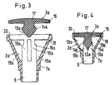
- FIG. 3 and 4 show a modified closure attachment 2a, which can be used together with the actuating attachment 1 and in which the likewise mushroom-shaped closure element 3a is not rigid, but is made of an elastically flexible material.
- the through-channels 19a are not formed in the stem 13a, but in a conically widening part of the pipe socket 7a. Accordingly, the radial projection 14a of the stem 13a is continuous in the circumferential direction and the undercut 15a is interrupted in the circumferential direction by the through channels 19a.
- the projection 14a has no axial distance from the undercut 15a, but is constantly in contact with it.
- the closure element 3a When the dispensing valve is opened, the closure element 3a is therefore not raised, but rather only its edge 16 is bent axially upward by the pressure of the foam, and in this way the closure element 3a is brought into the open position (not shown) with a delay. After the dispensing valve is closed, the opening edge 16 is bent back again until it rests against the edge 18 due to its return spring force and brought into the closed position. The opening and closing of the closure element 3a is therefore also delayed compared to the opening and closing of the dispensing valve.
- polygonal, e.g. quadrangular, closure elements and correspondingly adapted actuating attachments with the same design, as shown, can be provided.
Landscapes
- Chemical & Material Sciences (AREA)
- Dispersion Chemistry (AREA)
- Engineering & Computer Science (AREA)
- Mechanical Engineering (AREA)
- Containers And Packaging Bodies Having A Special Means To Remove Contents (AREA)
- Nozzles (AREA)
Description
Die Erfindung bezieht sich auf einen Sprühkopf für einen Sprühbehälter zur Ausgabe von Schaum, wobei der Sprühbehälter ein manuell betätigbares Ausgabeventil in einem Austrittskanal des Sprühkopfes und der Sprühkopf ein den Austrittskanal selbsttätig und gegenüber dem Ausgabeventil verzögert schließendes Verschlußelement stromunterhalb des Ausgabeventils aufweist und das Verschlußelement etwa pilzartig geformt ist, mit seinem Stiel axial in den Austrittskanal eingeführt ist und in der Schließstellung mit dem Rand seines Pilzkopfes am Rand der Austrittsöffnung des Austrittskanals und mit einem radialen Vorsprung des Stiels an einer Hinterschneidung im Austrittskanal, diese untergreifend, anliegt.The invention relates to a spray head for a spray container for dispensing foam, the spray container having a manually operable dispensing valve in an outlet channel of the spray head and the spray head having a closure element which closes the outlet channel automatically and with a delay relative to the dispensing valve, downstream of the dispensing valve, and the closure element is somewhat mushroom-like is formed, with its stem axially inserted into the outlet channel and in the closed position with the edge of its mushroom head on the edge of the outlet opening of the outlet channel and with a radial projection of the stem against an undercut in the outlet channel, engaging under it.
Bei einem bekannten Sprühkopf dieser Art (US-A 44 37 592) wird das Verschlußelement vor dem Ausgabeventil geöffnet und nach diesem hermetisch geschlossen. Bei der Ausgabe von Schaum aus einem Aerosol- bzw. Sprühbehälter (Sprühdose) ist man jedoch daran interessiert, daß das zunächst flüssig in dem Sprühbehälter enthaltene Aerosolprodukt beim Öffnen des Ausgabeventils nicht ungebremst aus dem Sprühkopf austritt, sondern zunächst vollständig aufschäumt. Wenn das Verschlußelement jedoch vor dem Ausgabeventil öffnet, kann die Aerosolflüssigkeit zumindest teilweise austreten, bevor sie vollständig aufgeschäumt ist. Ferner ist man auch daran interessiert, den Schaum nicht ungebremst austreten zu lassen, weil sich gezeigt hat, daß ein gebremst austretender Schaum eine höhere Schaumfestigkeit erhält. Wenn andererseits das Verschlußelement hermetisch schließt, kann der zwischen dem Ausgabeventil und der Auslaßöffnung verbleibende Produktrest in dem geschlossenen Austrittskanal nachschäumen und gegebenenfalls das Verschlußelement unter dem Druck des Schaums wieder öffnen, so daß weiterhin Schaum ausströmt.In a known spray head of this type (US-A 44 37 592), the closure element is opened in front of the dispensing valve and hermetically closed after it. When dispensing foam from an aerosol or spray container (spray can), however, one is interested in the fact that the aerosol product initially contained in liquid form in the spray container does not emerge from the spray head unchecked when the dispensing valve is opened, but initially foams up completely. However, if the closure element opens in front of the dispensing valve, the aerosol liquid can at least partially emerge before it is fully foamed. Furthermore, one is also interested in not letting the foam emerge unchecked, because it has been shown that a foam that emerges when braked has a higher foam strength. If, on the other hand, the closure element hermetically closes, the product residue remaining between the dispensing valve and the outlet opening can re-foam in the closed outlet channel and, if appropriate, open the closure element again under the pressure of the foam, so that foam continues to flow out.
Der Erfindung liegt die Aufgabe zugrunde, einen Sprühkopf der gattungsgemäßen Art anzugeben, bei dem der austretende Schaum eine höhere Festigkeit aufweist und ein Ausströmen von Schaum nach dem Schließen des Verschlußelements vermieden ist.The invention has for its object to provide a spray head of the generic type, in which the emerging foam has a higher strength and an outflow of foam is avoided after closing the closure element.
Erfindungsgemäß ist diese Aufgabe dadurch gelöst, daß das Öffnen des Verschlußelements gegenüber dem Öffnen des Ausgabeventils verzögert ist und das Verschlußelement in seiner Schließlage Gase, aber keine Flüssigkeiten austreten läßt, und daß zumindest der Pilzkopf aus elastisch biegsamem Material besteht.According to the invention this object is achieved in that the opening of the closure element is delayed compared to the opening of the dispensing valve and the closure element in its closed position allows gases but no liquids to escape, and that at least the mushroom head consists of an elastically flexible material.
Bei dieser Lösung wirkt das verzögert öffnende Verschlußelement zunächst wie eine Schaumaustrittsbremse, so daß die Schaumfestigkeit erhöht wird. Durch das nichthermetische Schließen und den weiterhin möglichen Gasaustritt wird gleichzeitig auch ein Nachschäumen und Ausströmen von Schaum vermieden. Der Rand des Pilzkopfes biegt sich unter dem Druck des Schaums gegenüber dem Öffnen des Ausgabeventils verzögert vom Rand der Austrittsöffnung des Austrittskanals weg, um den Austritt des Schaums freizugeben. Nach dem Schließen des Ausgabeventils bewegt sich der Rand des Pilzkopfes aufgrund seiner Eigenelastizität wieder verzögert mit nachlassendem Druck des Schaums in die Schließstellung zurück.With this solution, the delayed-opening closure element initially acts like a foam outlet brake, so that the foam strength is increased. Due to the non-hermetic closing and the still possible gas outlet, after-foaming and outflow of foam is avoided at the same time. The edge of the mushroom head bends under the pressure of the foam delayed away from the edge of the outlet opening of the outlet channel in order to expose the outlet of the foam. After the dispensing valve is closed, the edge of the mushroom head moves with a delay due to its inherent elasticity decreasing pressure of the foam back to the closed position.
Der Austrittskanal kann in einen ersten Abschnitt und einen mit diesem zusammensteckbaren, das Verschlußelement aufweisenden zweiten Abschnitt unterteilt sein. Hierbei kann der erste Abschnitt den herkömmlichen Austrittskanal bilden, in den der zweite Abschnitt in der gewünschten Ausgestaltung einfach eingesteckt werden kann.The outlet channel can be divided into a first section and a second section which can be plugged together and has the closure element. Here, the first section can form the conventional outlet channel, into which the second section can simply be inserted in the desired configuration.
Die Erfindung und ihre Weiterbildungen werden nachstehend anhand von Zeichnungen näher beschrieben. Es zeigen:
- Fig. 1
- einen Axialschnitt durch einen Sprühkopf in der Schließstellung, der keine beanspruchte Ausführungsform darstellt, sondern der Erläuterung der Wirkungsweise und des Aufbaus des erfindungsgemäßen Ausführungsbeispiels nach den Fig. 3 und 4 dient,
- Fig. 2
- den Sprühkopf nach Fig. 1 in der Öffnungsstellung,
- Fig. 3
- einen Axialschnitt durch einen Aufsatz eines Ausführungsbeispiels eines erfindungsgemäßen Sprühkopfes mit zugehörigem Verschlußelement in Explosionsdarstellung und
- Fig. 4
- den Aufsatz nach Fig. 3 bei eingesetztem Verschlußelement in der Schließstellung.
- Fig. 1
- 3 shows an axial section through a spray head in the closed position, which does not represent a claimed embodiment, but serves to explain the mode of operation and the structure of the exemplary embodiment according to FIGS. 3 and 4,
- Fig. 2
- 1 in the open position,
- Fig. 3
- an axial section through an attachment of an embodiment of a spray head according to the invention with associated closure element in an exploded view and
- Fig. 4
- 3 with the closure element inserted in the closed position.
Der Sprühkopf nach den Fig. 1 und 2 besteht aus einem Betätigungsaufsatz 1 für ein (nicht dargestelltes) Ausgabeventil eines Sprühbehälters zur Ausgabe von Schaum mit einem im Querschnitt etwa pilzkopfförmigen Verschlußaufsatz 2, in den ein Verschlußelement 3 in Form eines Pilzkopfes im Schnappsitz eingesetzt ist, und einer Schutzhaube 4.1 and 2 consists of an actuating attachment 1 for a (not shown) dispensing valve of a spray container for dispensing foam with an approximately mushroom-
Der Betätigungsaufsatz 1 hat ein vertikales Austrittsrohr 5, das einen ersten Abschnitt eines Austrittskanals 6 bildet und in das ein Rohrstutzen 7 des Verschlußaufsatzes 2 eingesetzt ist, wobei der Rohrstutzen 7 einen zweiten Abschnitt des Austrittskanals 6 bildet. Hierbei sind das Austrittsrohr 5 und der Rohrstutzen 7 im Reibschluß dicht zusammengehalten. Der axial untere Abschnitt des Austrittsrohres 5 bildet eine Fassung 8 zur Aufnahme des Austrittsendes eines Ausgaberohres des Ausgabeventils. Der Austrittskanal 6 ist teilweise durch eine sich quer in diesem erstreckende Prallwand 9 versperrt, an der die wässrige, aus dem Sprühbehälter freigegebene Aerosolflüssigkeit zunächst aufschäumen kann.The actuating attachment 1 has a
Die obere Wand 10 des Betätigungsaufsatzes 1 ist nur auf der einen (in Fig. 1 linken) Seite des Austrittsrohres 5 mit dem oberen Rand einer radial äußeren, auf den oberen Rand des Sprühbehälters im Schnappsitz aufsetzbaren Umfangswand 11 des Betätigungsaufsatzes 1 einteilig verbunden. Die Wand 10 besteht aus biegsamem Material. Daher kann durch Niederdrücken einer der Verbindungsstelle zwischen den Wänden 10 und 11 diametral gegenüberliegenden Betätigungsstufe 12 ein Druck auf das in die Fassung 8 eingreifende Ausgaberohr des Ausgabeventils ausgeübt werden. Durch das Niederdrücken des Ausgaberohrs, das zugleich einen Verschlußteil des Ausgabeventils bildet, wird das Ausgabeventil geöffnet.The
Das Verschlußelement 3 ist etwa pilzartig geformt und mit seinem Stiel 13 axial in den Austrittskanal 6 eingeführt. Der Stiel 13 hat einen radialen Vorsprung 14 in Form eines umlaufenden Wulstes, der eine Hinterschneidung 15 untergreift, die ebenfalls durch einen radial nach innen vorstehenden Wulst im Austrittskanal 6 gebildet wird. In der in Fig. 1 dargestellten Schließstellung des Verschlußelements 3 liegt dieses mit dem Rand 16 seines Pilzkopfes 17 am Rand 18 der Austrittsöffnung des Austrittskanals 6 an. Der radiale Vorsprung 14 hat in der Schließstellung einen axialen Abstand d von der Hinterschneidung 15, durch den der Hub des aus starrem Material bestehenden Verschlußelements 3 bestimmt und begrenzt wird. Axiale Durchgangskanäle 19 durchsetzen den radialen Vorsprung 14 bis auf die obere Seite des die Hinterschneidung 15 bildenden Vorsprungs. Der Pilzkopf 17 des Verschlußelements 3 ist in einer axialen Vertiefung 20 in der pilzkopfartigen Erweiterung des Verschlußaufsatzes 2 weitgehend bündig versenkt.The
Wenn die Betätigungsstufe 12 niedergedrückt und das Ausgabeventil geöffnet wird, strömt der Behälterinhalt unter dem Druck eines Treibmittels über das Ausgabeventil und dessen Ausgaberohr gegen die Prallwand 9, von der es unter Aufschäumung in das Austrittsrohr 5 und den Rohrstutzen 7 umgeleitet wird. Hier trifft es auf das die Schließstellung nach Fig. 1 einnehmende Verschlußelement 3, wobei dieses gegen seine Schwerkraft (bzw. sein Gewicht) unter dem Druck des Schaums verzögert in die Öffnungsstellung nach Fig. 2 angehoben wird und wie eine Schaumaustrittsbremse wirkt. Durch diesen "gebremsten" Austritt des Schaums wird dessen Festigkeit erhöht.When the
Sobald der Druck von der Betätigungstaste 12 weggenommen wird, schließt sich das Ausgabeventil, während das Verschlußelement 3 weiterhin unter dem Druck des Schaums die Öffnungsstellung beibehält.As soon as the pressure is released from the
In aufrechter Lage des Sprühbehälters und dementsprechend vertikaler Lage des Ausgangskanals 6 sinkt nun das Verschlußelement 3 bei nachlassendem Schaumdruck in die Schließstellung zurück. Alternativ kann das Verschlußelement 3 auch manuell beim Abstreifen des ausgetretenen Schaums in die Schließstellung zurückgedrückt werden. In der Schließstellung kann durch den nicht hermetisch dichten Schließspalt zwischen Verschlußelement 3 und Verschlußaufsatz 2 weiterhin Gas austreten, während der Schaum bzw. sich in dem Austrittskanal 6 bildende Flüssigkeit zurückgehalten wird und gleichzeitig verhindert wird, daß der im Austrittskanal verbleibende Produktrest sich unter Luftzutritt verändern kann.In the upright position of the spray container and accordingly the vertical position of the
Die Fig. 3 und 4 zeigen einen abgewandelten Verschlußaufsatz 2a, der zusammen mit dem Betätigungsaufsatz 1 verwendet werden kann und bei dem das ebenfalls pilzkopfförmige Verschlußelement 3a nicht starr, sondern aus elastisch biegsamem Material hergestellt ist. Die Durchgangskanäle 19a sind nicht im Stiel 13a, sondern in einem sich konisch aufweitenden Teil des Rohrstutzens 7a ausgebildet. Dementsprechend ist der radiale Vorsprung 14a des Stiels 13a in Umfangsrichtung durchgehend ausgebildet und die Hinterschneidung 15a in Umfangsrichtung durch die Durchgangskanäle 19a unterbrochen. Der Vorsprung 14a hat keinen axialen Abstand von der Hinterschneidung 15a, sondern liegt ständig an dieser an.3 and 4 show a modified
Beim Öffnen des Ausgabeventils wird das Verschlußelement 3a mithin nicht angehoben, sondern lediglich sein Rand 16 durch den Druck des Schaums axial nach oben gebogen und auf diese Weise das Verschlußelement 3a verzögert in die (nicht dargestellte) Öffnungsstellung gebracht. Nach dem Schließen des Ausgabeventils wird der Öffnungsrand 16 wieder bis zur Anlage an den Rand 18 aufgrund seiner Rückstellfederkraft zurückgebogen und in die Schließstellung gebracht. Das Öffnen und Schließen des Verschlußelements 3a ist daher ebenfalls jeweils gegenüber dem Öffnen und Schließen des Ausgabeventils verzögert.When the dispensing valve is opened, the
Anstelle in der Draufsicht kreisförmiger Verschlußelemente, wie dargestellt, können auch mehreckige, z.B. viereckige, Verschlußelemente und entsprechend in der Form angepaßte Betätigungsaufsätze bei im übrigen gleicher Ausbildung, wie dargestellt, vorgesehen sein.Instead of circular closure elements in plan view, as shown, polygonal, e.g. quadrangular, closure elements and correspondingly adapted actuating attachments with the same design, as shown, can be provided.
Claims (2)
- A spray head for a spray container for dispensing foam, wherein the spray container has a manually actuable dispensing valve in a discharge passage (6) of the spray head and downstream of the dispensing valve the spray head has a closure element (3a) which closes the discharge passage (6) automatically and with a delay relative to the dispensing valve and the closure element (3a) is of an approximately mushroom-like shape, is inserted with its stem (13a) axially into the discharge passage (6) and in the closure position bears with the edge (16) of its mushroom head (17) against the edge (18) of the discharge opening of the discharge passage (6) and with a radial projection (14a) of the stem (13a) against an undercut configuration (15a) in the discharge passage (6), engaging under said undercut configuration, characterised in that opening of the closure element (3a) is delayed relative to opening of the dispensing valve and in its closed position the closure element (3a) allows gases but no liquids to escape, and that at least the mushroom head (17) comprises elastically flexible material.
- A spray head according to claim 1 characterised in that the discharge passage (6) is subdivided into a first portion (5) and a second portion (7a) which can be fitted together with the first portion and which has the closure element (3a).
Applications Claiming Priority (5)
| Application Number | Priority Date | Filing Date | Title |
|---|---|---|---|
| DE3909792 | 1989-03-24 | ||
| DE3909792 | 1989-03-24 | ||
| DE3931679 | 1989-09-22 | ||
| DE3931679A DE3931679A1 (en) | 1989-03-24 | 1989-09-22 | SPRAY HEAD FOR A SPRAY CONTAINER FOR DISPENSING FOAM |
| EP90105423A EP0388947B1 (en) | 1989-03-24 | 1990-03-22 | Sprayhead for a spray container for dispensing foam |
Related Parent Applications (3)
| Application Number | Title | Priority Date | Filing Date |
|---|---|---|---|
| EP90105423.9 Division | 1990-03-22 | ||
| EP90105423A Division-Into EP0388947B1 (en) | 1989-03-24 | 1990-03-22 | Sprayhead for a spray container for dispensing foam |
| EP90105423A Division EP0388947B1 (en) | 1989-03-24 | 1990-03-22 | Sprayhead for a spray container for dispensing foam |
Publications (2)
| Publication Number | Publication Date |
|---|---|
| EP0551146A1 EP0551146A1 (en) | 1993-07-14 |
| EP0551146B1 true EP0551146B1 (en) | 1995-04-26 |
Family
ID=25879177
Family Applications (3)
| Application Number | Title | Priority Date | Filing Date |
|---|---|---|---|
| EP93103461A Expired - Lifetime EP0551146B1 (en) | 1989-03-24 | 1990-03-22 | Sprayhead for a spray container for dispensing foam |
| EP90105423A Expired - Lifetime EP0388947B1 (en) | 1989-03-24 | 1990-03-22 | Sprayhead for a spray container for dispensing foam |
| EP93103462A Expired - Lifetime EP0550409B1 (en) | 1989-03-24 | 1990-03-22 | Sprayhead for a spray container for dispensing foam |
Family Applications After (2)
| Application Number | Title | Priority Date | Filing Date |
|---|---|---|---|
| EP90105423A Expired - Lifetime EP0388947B1 (en) | 1989-03-24 | 1990-03-22 | Sprayhead for a spray container for dispensing foam |
| EP93103462A Expired - Lifetime EP0550409B1 (en) | 1989-03-24 | 1990-03-22 | Sprayhead for a spray container for dispensing foam |
Country Status (10)
| Country | Link |
|---|---|
| EP (3) | EP0551146B1 (en) |
| JP (1) | JP2867179B2 (en) |
| AR (1) | AR244577A1 (en) |
| AU (1) | AU624933B2 (en) |
| BR (1) | BR9005967A (en) |
| CA (1) | CA2028850A1 (en) |
| DE (4) | DE3931679A1 (en) |
| ES (3) | ES2045604T3 (en) |
| HU (1) | HU214724B (en) |
| WO (1) | WO1990011236A1 (en) |
Families Citing this family (21)
| Publication number | Priority date | Publication date | Assignee | Title |
|---|---|---|---|---|
| FR2660635B1 (en) * | 1990-04-10 | 1994-01-14 | Marthe Lucas | HAIR CREAM DISPENSING HAIRDRESSER. |
| DE4108428A1 (en) * | 1991-03-15 | 1992-09-17 | Wiegner Georg Dipl Kaufm | Dispenser esp. for pressurised fluids - has valve of movable valve disc located in container opening, and includes counter-seal |
| FR2676714B1 (en) * | 1991-05-21 | 1993-09-24 | Oreal | CONTAINER PROVIDED WITH AN ELASTIC CLOSURE DEVICE. |
| CH680359A5 (en) * | 1991-08-28 | 1992-08-14 | Supermatic Kunststoff Ag | |
| DE9114142U1 (en) * | 1991-11-13 | 1993-03-11 | PCT Powder Coating Technologies GmbH, 7482 Krauchenwies | Device for feeding colour powder during powder coating |
| FR2692231B1 (en) * | 1992-06-11 | 1996-04-26 | Avitex | BROADCAST NOZZLE AND BROADCASTING HEAD FOR PRESSURIZED CONTAINER. |
| WO1994012406A1 (en) * | 1992-11-23 | 1994-06-09 | Deutsche Präzisions Ventil Gmbh | Actuator for an aerosol container |
| NL9300517A (en) * | 1993-03-23 | 1994-10-17 | Airspray Int Bv | Foam forming assembly, a suitable spray head and a spray can comprising such an assembly. |
| DE9411622U1 (en) * | 1994-07-18 | 1994-11-17 | Coster Tecnologie Speciali Spa | Device for the metered discharge of a flowable medium |
| DE4426120A1 (en) * | 1994-07-22 | 1996-01-25 | Coster Tecnologie Speciali Spa | Spray head for a container for a pressurized fluid |
| FR2724154B1 (en) * | 1994-09-05 | 1997-01-17 | Oreal | PRODUCT DISTRIBUTOR NOZZLE, ESPECIALLY FOAM FOR PRESSURIZED VALVE CONTAINER |
| DE4437439A1 (en) * | 1994-10-20 | 1996-04-25 | Wella Ag | Device with at least one non-slip handling or operating surface of a device |
| DE9419268U1 (en) * | 1994-12-01 | 1995-01-26 | Josef Wischerath Gmbh & Co. Kg, 50259 Pulheim | donor |
| DE19607691A1 (en) * | 1996-02-29 | 1997-09-04 | Coster Tecnologie Speciali Spa | Foam head |
| US7011978B2 (en) | 2001-08-17 | 2006-03-14 | Micron Technology, Inc. | Methods of forming capacitor constructions comprising perovskite-type dielectric materials with different amount of crystallinity regions |
| DE10232863A1 (en) * | 2002-07-16 | 2004-02-05 | Hüttlin, Herbert, Dr.h.c. | Atomizing nozzle with a rotating annular gap |
| DE10321902A1 (en) | 2003-05-06 | 2004-12-09 | Ing. Erich Pfeiffer Gmbh | Discharge device for at least one medium |
| FR2980125B1 (en) * | 2011-09-21 | 2016-01-22 | Oreal | DISTRIBUTION HEAD WITH TWO RESTRICTED NOZZLES |
| CN103286020B (en) * | 2013-07-02 | 2016-03-02 | 江苏新天宝机械有限公司 | Cleaning fluid shower nozzle in a kind of tank body |
| JP6383207B2 (en) * | 2014-07-31 | 2018-08-29 | 株式会社吉野工業所 | Discharge container that discharges contents to discharge surface |
| JP6745299B2 (en) * | 2018-08-01 | 2020-08-26 | 株式会社吉野工業所 | Discharge container that discharges contents on the discharge surface |
Family Cites Families (11)
| Publication number | Priority date | Publication date | Assignee | Title |
|---|---|---|---|---|
| US2913749A (en) * | 1958-03-19 | 1959-11-24 | John M Wittke | Applicator for pressurized package |
| US2954904A (en) * | 1958-10-13 | 1960-10-04 | Joseph B Potoczky | Gas pressure type dispensing container cap |
| GB1226565A (en) * | 1967-04-07 | 1971-03-31 | ||
| ES419697A1 (en) * | 1972-10-18 | 1976-03-16 | Ivanov Mantchev | Valvular liquid dispensing closure |
| US3874563A (en) * | 1973-06-19 | 1975-04-01 | Gilbert Schwartzman | Applicator having multiple valve assemblies |
| US3976216A (en) | 1974-12-26 | 1976-08-24 | Thermo Electron Corporation | Sterile bottle closure |
| CA1166203A (en) * | 1979-12-21 | 1984-04-24 | Luigi Del Bon | Self-sealing actuating device for mounting on a discharge valve of a pressurized container |
| US4314658A (en) * | 1980-01-30 | 1982-02-09 | Laauwe Robert H | Viscous product dispensing squeeze bottle having a self-venting automatic shut-off valve |
| ATE49716T1 (en) * | 1985-01-28 | 1990-02-15 | Earl Wright Co | FOAM GENERATOR. |
| DE8524966U1 (en) * | 1985-08-31 | 1987-01-22 | Bramlage Gmbh, 2842 Lohne | Screw cap for bottles or similar. |
| US4813577A (en) * | 1988-03-04 | 1989-03-21 | Carow International, Inc. | Multiple flow dispensing cap |
-
1989
- 1989-09-22 DE DE3931679A patent/DE3931679A1/en not_active Ceased
-
1990
- 1990-03-01 AR AR90316305A patent/AR244577A1/en active
- 1990-03-21 CA CA002028850A patent/CA2028850A1/en not_active Abandoned
- 1990-03-21 WO PCT/EP1990/000460 patent/WO1990011236A1/en not_active Ceased
- 1990-03-21 JP JP2504726A patent/JP2867179B2/en not_active Expired - Fee Related
- 1990-03-21 BR BR909005967A patent/BR9005967A/en not_active IP Right Cessation
- 1990-03-21 AU AU52737/90A patent/AU624933B2/en not_active Ceased
- 1990-03-21 HU HU902832A patent/HU214724B/en not_active IP Right Cessation
- 1990-03-22 EP EP93103461A patent/EP0551146B1/en not_active Expired - Lifetime
- 1990-03-22 DE DE59009931T patent/DE59009931D1/en not_active Expired - Fee Related
- 1990-03-22 ES ES90105423T patent/ES2045604T3/en not_active Expired - Lifetime
- 1990-03-22 DE DE59008985T patent/DE59008985D1/en not_active Expired - Fee Related
- 1990-03-22 EP EP90105423A patent/EP0388947B1/en not_active Expired - Lifetime
- 1990-03-22 ES ES93103461T patent/ES2071521T3/en not_active Expired - Lifetime
- 1990-03-22 ES ES93103462T patent/ES2080545T3/en not_active Expired - Lifetime
- 1990-03-22 EP EP93103462A patent/EP0550409B1/en not_active Expired - Lifetime
- 1990-03-22 DE DE90105423T patent/DE59002788D1/en not_active Expired - Fee Related
Also Published As
| Publication number | Publication date |
|---|---|
| WO1990011236A1 (en) | 1990-10-04 |
| DE3931679A1 (en) | 1990-09-27 |
| DE59008985D1 (en) | 1995-06-01 |
| EP0550409A1 (en) | 1993-07-07 |
| HU214724B (en) | 1998-05-28 |
| DE59009931D1 (en) | 1996-01-11 |
| EP0550409B1 (en) | 1995-11-29 |
| JPH03504826A (en) | 1991-10-24 |
| EP0388947A1 (en) | 1990-09-26 |
| ES2045604T3 (en) | 1994-01-16 |
| CA2028850A1 (en) | 1990-09-25 |
| HUT56036A (en) | 1991-07-29 |
| JP2867179B2 (en) | 1999-03-08 |
| EP0551146A1 (en) | 1993-07-14 |
| EP0388947B1 (en) | 1993-09-22 |
| HU902832D0 (en) | 1991-06-28 |
| AU624933B2 (en) | 1992-06-25 |
| AR244577A1 (en) | 1993-11-30 |
| ES2071521T3 (en) | 1995-06-16 |
| BR9005967A (en) | 1991-08-06 |
| DE59002788D1 (en) | 1993-10-28 |
| ES2080545T3 (en) | 1996-02-01 |
| AU5273790A (en) | 1990-10-22 |
Similar Documents
| Publication | Publication Date | Title |
|---|---|---|
| EP0551146B1 (en) | Sprayhead for a spray container for dispensing foam | |
| DE3244645C2 (en) | ||
| EP0850177B1 (en) | Self-closing seal with a sealing membrane | |
| DE69413845T2 (en) | TOGGLE OPERATED DISPENSER LOCK | |
| EP0084638B1 (en) | Dispenser for pasty products | |
| DE69206988T2 (en) | Device for injecting a predetermined dose of a medium and method for filling this device | |
| DE69706478T2 (en) | Container for mixing and removing two components contained therein | |
| CH617146A5 (en) | ||
| EP0097972A1 (en) | Dispenser for pastes | |
| DE2529139A1 (en) | AUTOMATIC LOCKING FOR A PRESSURE VESSEL FOR DISPENSING PRODUCT IN FOAM FORM | |
| DE202006021269U1 (en) | Aerosolsprühaktuator | |
| EP1513426A1 (en) | Dispenser head with a check valve | |
| EP0347546A2 (en) | Dispenser for paste-like products | |
| DE3425900A1 (en) | DEVICE WITH DROP METER FOR DISPENSING A LIQUID OR PASTOUS SUBSTANCE | |
| DE68903116T2 (en) | DISPENSER FOR PASTOESE PRODUCTS, PROVIDED WITH AN AXIAL ACTUATING HEAD FOR LATERAL OUTPUT, AND COVERING ELEMENT FOR ITS OUTPUT OPENING. | |
| DE60310319T2 (en) | Aerosol dispenser | |
| DE2153445A1 (en) | Actuator for controlling the delivery of material from a pressure vessel | |
| EP0691284A2 (en) | Dispenser for pasty substances | |
| DE69500279T2 (en) | Liquid dispenser with a dispensing valve and a push button | |
| DE3006124A1 (en) | LOCKING DEVICE AND PROVIDED PRESSURE TANK | |
| EP1118554A1 (en) | Spray cap with integral head | |
| WO1995021097A1 (en) | Flexible sealing diaphragm | |
| DE1930969A1 (en) | Cap for aerosol spray cans | |
| DE2018692B2 (en) | Spray head for aerosol containers | |
| EP1481734B1 (en) | Closure for a spray head |
Legal Events
| Date | Code | Title | Description |
|---|---|---|---|
| PUAI | Public reference made under article 153(3) epc to a published international application that has entered the european phase |
Free format text: ORIGINAL CODE: 0009012 |
|
| AC | Divisional application: reference to earlier application |
Ref document number: 388947 Country of ref document: EP |
|
| AK | Designated contracting states |
Kind code of ref document: A1 Designated state(s): DE ES FR GB IT |
|
| 17P | Request for examination filed |
Effective date: 19930529 |
|
| 17Q | First examination report despatched |
Effective date: 19940301 |
|
| GRAA | (expected) grant |
Free format text: ORIGINAL CODE: 0009210 |
|
| AC | Divisional application: reference to earlier application |
Ref document number: 388947 Country of ref document: EP |
|
| AK | Designated contracting states |
Kind code of ref document: B1 Designated state(s): DE ES FR GB IT |
|
| ITF | It: translation for a ep patent filed | ||
| GBT | Gb: translation of ep patent filed (gb section 77(6)(a)/1977) |
Effective date: 19950501 |
|
| REF | Corresponds to: |
Ref document number: 59008985 Country of ref document: DE Date of ref document: 19950601 |
|
| ET | Fr: translation filed | ||
| REG | Reference to a national code |
Ref country code: ES Ref legal event code: FG2A Ref document number: 2071521 Country of ref document: ES Kind code of ref document: T3 |
|
| PLBE | No opposition filed within time limit |
Free format text: ORIGINAL CODE: 0009261 |
|
| 26N | No opposition filed | ||
| REG | Reference to a national code |
Ref country code: GB Ref legal event code: IF02 |
|
| PGFP | Annual fee paid to national office [announced via postgrant information from national office to epo] |
Ref country code: ES Payment date: 20080326 Year of fee payment: 19 |
|
| PGFP | Annual fee paid to national office [announced via postgrant information from national office to epo] |
Ref country code: GB Payment date: 20080327 Year of fee payment: 19 |
|
| PGFP | Annual fee paid to national office [announced via postgrant information from national office to epo] |
Ref country code: FR Payment date: 20080317 Year of fee payment: 19 Ref country code: DE Payment date: 20080430 Year of fee payment: 19 |
|
| PGFP | Annual fee paid to national office [announced via postgrant information from national office to epo] |
Ref country code: IT Payment date: 20080329 Year of fee payment: 19 |
|
| GBPC | Gb: european patent ceased through non-payment of renewal fee |
Effective date: 20090322 |
|
| REG | Reference to a national code |
Ref country code: FR Ref legal event code: ST Effective date: 20091130 |
|
| PG25 | Lapsed in a contracting state [announced via postgrant information from national office to epo] |
Ref country code: DE Free format text: LAPSE BECAUSE OF NON-PAYMENT OF DUE FEES Effective date: 20091001 |
|
| PG25 | Lapsed in a contracting state [announced via postgrant information from national office to epo] |
Ref country code: GB Free format text: LAPSE BECAUSE OF NON-PAYMENT OF DUE FEES Effective date: 20090322 Ref country code: FR Free format text: LAPSE BECAUSE OF NON-PAYMENT OF DUE FEES Effective date: 20091123 |
|
| REG | Reference to a national code |
Ref country code: ES Ref legal event code: FD2A Effective date: 20090323 |
|
| PG25 | Lapsed in a contracting state [announced via postgrant information from national office to epo] |
Ref country code: ES Free format text: LAPSE BECAUSE OF NON-PAYMENT OF DUE FEES Effective date: 20090323 |
|
| PG25 | Lapsed in a contracting state [announced via postgrant information from national office to epo] |
Ref country code: IT Free format text: LAPSE BECAUSE OF NON-PAYMENT OF DUE FEES Effective date: 20090322 |