EP0551113A2 - Verfahren zur Herstellung einer Leiterplatte für ein motorgetriebenes Betätigungselement und ein solches Betätigungselement - Google Patents
Verfahren zur Herstellung einer Leiterplatte für ein motorgetriebenes Betätigungselement und ein solches Betätigungselement Download PDFInfo
- Publication number
- EP0551113A2 EP0551113A2 EP93100162A EP93100162A EP0551113A2 EP 0551113 A2 EP0551113 A2 EP 0551113A2 EP 93100162 A EP93100162 A EP 93100162A EP 93100162 A EP93100162 A EP 93100162A EP 0551113 A2 EP0551113 A2 EP 0551113A2
- Authority
- EP
- European Patent Office
- Prior art keywords
- connector
- wiring board
- motor
- housing
- conductive pattern
- Prior art date
- Legal status (The legal status is an assumption and is not a legal conclusion. Google has not performed a legal analysis and makes no representation as to the accuracy of the status listed.)
- Granted
Links
Images

Classifications
-
- H—ELECTRICITY
- H02—GENERATION; CONVERSION OR DISTRIBUTION OF ELECTRIC POWER
- H02K—DYNAMO-ELECTRIC MACHINES
- H02K5/00—Casings; Enclosures; Supports
- H02K5/04—Casings or enclosures characterised by the shape, form or construction thereof
- H02K5/22—Auxiliary parts of casings not covered by groups H02K5/06-H02K5/20, e.g. shaped to form connection boxes or terminal boxes
- H02K5/225—Terminal boxes or connection arrangements
-
- H—ELECTRICITY
- H02—GENERATION; CONVERSION OR DISTRIBUTION OF ELECTRIC POWER
- H02K—DYNAMO-ELECTRIC MACHINES
- H02K7/00—Arrangements for handling mechanical energy structurally associated with dynamo-electric machines, e.g. structural association with mechanical driving motors or auxiliary dynamo-electric machines
- H02K7/10—Structural association with clutches, brakes, gears, pulleys or mechanical starters
- H02K7/116—Structural association with clutches, brakes, gears, pulleys or mechanical starters with gears
- H02K7/1163—Structural association with clutches, brakes, gears, pulleys or mechanical starters with gears where at least two gears have non-parallel axes without having orbital motion
- H02K7/1166—Structural association with clutches, brakes, gears, pulleys or mechanical starters with gears where at least two gears have non-parallel axes without having orbital motion comprising worm and worm-wheel
-
- H—ELECTRICITY
- H02—GENERATION; CONVERSION OR DISTRIBUTION OF ELECTRIC POWER
- H02K—DYNAMO-ELECTRIC MACHINES
- H02K11/00—Structural association of dynamo-electric machines with electric components or with devices for shielding, monitoring or protection
-
- H—ELECTRICITY
- H02—GENERATION; CONVERSION OR DISTRIBUTION OF ELECTRIC POWER
- H02K—DYNAMO-ELECTRIC MACHINES
- H02K2211/00—Specific aspects not provided for in the other groups of this subclass relating to measuring or protective devices or electric components
- H02K2211/03—Machines characterised by circuit boards, e.g. pcb
Definitions
- the invention relates to a method according to the preamble part of claim 1 and to a motor-driven actuator according to the preamble parts of independent claims 7, 10 and 19.
- the actuator preferably is employed for adjusting the position of a ventilation flap in an automobile air conditioning system and/or a heating system and/or a ventilating system, and under the control of a supervising control unit.
- the bearing hole and the conductive pattern are integrally molded to the wiring board, the bearing hole and the conductive pattern can be manufactured without any displacement or within a very small range of displacement. Therefore, it is possible to avoid a dislocation or to make a dislocation very small for the contact positional relation between the conductive brush rotating together with the output shaft and the conductive pattern on the wiring board.
- the housing of the actuator can be shared.
- the connector passing opening size is sufficiently large in order to allow the use of any type of connector.
- the gap between the connector being used and the connector passing opening does not remain open, but is closed by the cover thus preventing dust and humidity from entering into the housing.
- actuators In cars, actuators often serve to adjust moveable parts, e.g a flap in an air conditioning system or in a heating or ventilating system, supervised by an exterior control system. Particularly, the opening angle or the like of the flap is to be accurately controlled.
- the content of the control differs with the manufacturer and the vehicle model. It thus becomes necessary to change the electric circuit in the housing as well as the connector of the actuator if the actuator is intended to be used in another vehicle model or for another manufacturer.
- the motor, the reduction gear mechanism and the like can be shared, even if the content of the control varies.
- the housing of the actuator usually is manufactured by injection molding of plastics or the like. However, due to the various sizes and shapes of the connector, depending from the automobile, manufacturer and the vehicle model, until now, it is necessary to manufacture differently sized housings or housing parts in respectively sized injection molds. This considerably increases the manufacturing costs for the actuators.
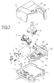
- upper and lower housings 1 and 2 made of plastic are formed by injection molding, e.g. in an electrically insulated plastic mold, and are secured with each other by passing fixing screws (not shown) through threaded holes 3 and 4.
- a motor mounting plate 5 is secured to a motor 7 with mounting screws 6, and its foot is inserted into a slit 8 formed in the floor portion of the lower housing 2 to the thereby secured to the lower housing 2.
- a worm gear 9 is mounted to a rotatable shaft 7a of the motor 7, and a supporting plate 11 to be inserted in the lower housing 2 is pressed against the tip of the worm gear 9.
- a reduction gear group 12 reduces the rotating speed of the motor 7 for transmission, and is rotatably fitted in shafts 13 vertically provided on the lower housing 2.
- the output shaft 15 is integrally formed so that the rotation of the motor 7 drives the output shaft 15 through the reduction gear group 12 for rotation.
- the tip of the output shaft 15 projects outside through a hole 16 drilled in the upper housing 1 to be connected to a link (not shown) in order to drive a body to be driven such as an air conditioning door for an automobile.
- a conductive brush 17 On the underside of the output gear 14, there is secured a conductive brush 17, which is rotated around the output shaft 15 together therewith.
- a control circuit to control the operation of the motor 7 On a wiring board 20, a control circuit to control the operation of the motor 7 is provided.
- a conductive pattern 22 formed of highly electrically-conductive metallic plate is formed on a concentric circle to come into contact with the rotating conductive brush 17.
- a diode 23 is connected in the control circuit.
- the shape of the conductive pattern 22 is schematically shown in Fig. 1.
- a bearing hole 25 in which the lower end of the output shaft 15 is rotatably fitted is formed in the wiring board 20 so that the conductive brush 17 is rotated around the bearing hole 25.
- the wiring board 20 is a plate-shaped body molded using electrically-insulated plastic material, and during molding, the conductive pattern 22 is inserted and integrally molded to the wiring board 20, and the bearing hole 25 is formed by the molding at the same time.
- the conductive pattern 22 and the bearing hole 25 are integrally molded when the wiring board 20 is molded, and the conductive pattern 22 and the bearing hole 25 can be manufactured within a very small range of displacement.
- connecting terminals 26 for connecting to an external control circuit and power supply terminals 27 for connecting to a power terminal 7a of the motor 7.
- the power supply terminals 27 are bent after molding.
- Connecting terminals 26 are disposed in a connector 28 which has been plastic molded integrally with the wiring board 20.
- a connector 28 which has been plastic molded integrally with the wiring board 20.
- the wiring board 20 and the connector 28 which are thus integrally formed can be freely replaced in accordance with the specification of an automotive air conditioner for which the motor actuator is used. Therefore, the shape and the like of the conductive pattern 22 vary depending on the type of the wiring board 20, and the conductive brush 17 may be changed accordingly.
- the number of the connecting terminals 26 within the connector 28 is various: from 2 pieces to ten pieces, and the shape and the size of the connector 28 become different respectively.
- the connector 28 is disposed to project outside from the housings 1 and 2.
- the connector through-holes 29 are formed to a sufficient size to allow the largest connector 28 for use with a motor actuator of the present embodiment to pass through. Therefore, even if any wiring board 20 and connector 28 are used, the connector 28 can pass through the connector through-holes 29, and therefore there is no need for replacing the upper and lower housings 1 and 2.
- the size of the connector through-hole 29 is too large for the connector 28 is almost all cases, and there will be a gap between the connector 28 and the connector through-hole 29.
- a plate-shaped cover 30 to fill up the gap between the connector 28 and the connector through-hole 29 is integrally formed with the connector 28 or the like to project sideways.
- the cover 30 is disposed so that its outer edge portion adheres closely to the inner surface side of the both housings 1 and 2 to completely fill up the gap between the connector 28 and the connector through-hole 29.
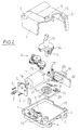
- Fig. 2 illustrates a second embodiment according to the present invention, in which the wiring board 20 is formed of the so-called printed board, and is separated from the connector 28 and the like.
- therminals 31 formed in the wiring board 20 and terminals 32 projectingly provided on the rear surface of the connector 28 are connected together by soldering, and the wiring board 20 and the connector 28 can be replaced as a unit.
- a motor actuator of the present invention by replacing only the electric circuit and the connector, it is possible to cope with various different specifications, particularly to share a housing even if the specification of the motor actuator is different. Therefore, there is no need for preparing any plastic molding die for the housing for each specification, thus greatly reducing the manufacturing cost.
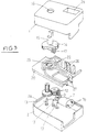
- Fig. 3 shows a third embodiment according to the present invention, in which the connector 28 is formed on the upper surface side of the upper housing 1, and the connecting terminals 26 are bent upward after molding to be positioned within the connector 28.
- the wiring board 20 is individually formed separately from the connector 28, and if the shape of the connector 28 is changed, it is necessary to change the upper housing 1. Also, on a staged portion 2a formed on the upper end edge of the lower housing 2, the wiring board 20 is placed, and the motor 7 and the reduction gear group 12 are disposed under the wiring board 20.
- a shaft 13 for supporting gear 10 of the reduction gear group 12 is integrally and vertically provided on the lower housing 2, and its upper end engages with a receiver 33 formed in the underside of the wiring board 20.
Landscapes
- Engineering & Computer Science (AREA)
- Power Engineering (AREA)
- Air-Conditioning For Vehicles (AREA)
- Motor Or Generator Frames (AREA)
- Connection Of Motors, Electrical Generators, Mechanical Devices, And The Like (AREA)
Applications Claiming Priority (6)
| Application Number | Priority Date | Filing Date | Title |
|---|---|---|---|
| JP20592 | 1992-01-06 | ||
| JP205/92 | 1992-01-06 | ||
| JP25622792A JPH06113504A (ja) | 1992-09-25 | 1992-09-25 | モータアクチュエータ |
| JP256227/92 | 1992-09-25 | ||
| JP4258029A JP2977388B2 (ja) | 1992-01-06 | 1992-09-28 | モータアクチュエータ |
| JP258029/92 | 1992-09-28 |
Publications (3)
| Publication Number | Publication Date |
|---|---|
| EP0551113A2 true EP0551113A2 (de) | 1993-07-14 |
| EP0551113A3 EP0551113A3 (de) | 1994-02-09 |
| EP0551113B1 EP0551113B1 (de) | 1996-09-11 |
Family
ID=27274346
Family Applications (1)
| Application Number | Title | Priority Date | Filing Date |
|---|---|---|---|
| EP93100162A Expired - Lifetime EP0551113B1 (de) | 1992-01-06 | 1993-01-07 | Verfahren zur Herstellung einer Leiterplatte für ein motorgetriebenes Betätigungselement und ein solches Betätigungselement |
Country Status (3)
| Country | Link |
|---|---|
| EP (1) | EP0551113B1 (de) |
| DE (1) | DE69304552T2 (de) |
| ES (1) | ES2094941T3 (de) |
Cited By (13)
| Publication number | Priority date | Publication date | Assignee | Title |
|---|---|---|---|---|
| EP0639884A1 (de) * | 1993-08-17 | 1995-02-22 | Bayerische Motoren Werke Aktiengesellschaft | Elektrische Antriebseinheit |
| EP0681359A1 (de) * | 1994-05-05 | 1995-11-08 | BITRON S.p.A. | Elektromechanischer Antrieb mit Gehäuse zum Bewahren und Tragen von Komponenten |
| FR2750542A1 (fr) * | 1996-06-27 | 1998-01-02 | Ecia Equip Composants Ind Auto | Dispositif de raccordement electrique pour moteur a courant continu |
| WO2000049634A1 (de) * | 1999-02-20 | 2000-08-24 | Robert Bosch Gmbh | Schaltmodul und stellmotor mit einem schaltmodul |
| EP1130742A1 (de) * | 2000-03-03 | 2001-09-05 | Molon Motor & Coil Corporation | Miniaturmotor mit Getriebegehäuse |
| EP1168579A1 (de) * | 2000-06-23 | 2002-01-02 | SAIA-Burgess Electronics AG | Anordnung eines Elektromotors mit mindestens einem Anschluss |
| EP1633033A1 (de) * | 2004-09-06 | 2006-03-08 | Delta Electronics, Inc. | Verbindermodul und Motor ausgestattet mit diesem |
| EP1196980A4 (de) * | 1999-05-21 | 2006-03-15 | Molon Motor & Coil Corp | Kompakter miniaturmotor |
| US7270577B2 (en) | 2004-08-18 | 2007-09-18 | Delta Electronics, Inc. | Connector module and motor utilizing the same |
| FR2923893A1 (fr) * | 2007-11-19 | 2009-05-22 | Fagorbrandt Sas Soc Par Action | Dispositif de securite d'un bruleur a gaz. |
| US8201478B2 (en) | 2009-04-29 | 2012-06-19 | Molon Motor And Coil Corp. | Gear box for ice dispenser |
| CN107528426A (zh) * | 2016-06-17 | 2017-12-29 | 美蓓亚三美株式会社 | 旋转装置以及具备具有该旋转装置的空调系统的交通工具 |
| US10190810B2 (en) | 2014-05-28 | 2019-01-29 | Molon Motor & Coil Corporation | Miniaturized motor assembly |
Family Cites Families (3)
| Publication number | Priority date | Publication date | Assignee | Title |
|---|---|---|---|---|
| US4795867A (en) * | 1986-01-17 | 1989-01-03 | Diesel Kiki Co., Ltd. | Motor actuator for air conditioning system |
| US4879803A (en) * | 1987-08-14 | 1989-11-14 | Asmo Co., Ltd. | Method for mounting a plurality of brushes |
| GB8821103D0 (en) * | 1988-09-08 | 1988-10-05 | Lucas Ind Plc | Electrical circuit element |
-
1993
- 1993-01-07 EP EP93100162A patent/EP0551113B1/de not_active Expired - Lifetime
- 1993-01-07 ES ES93100162T patent/ES2094941T3/es not_active Expired - Lifetime
- 1993-01-07 DE DE69304552T patent/DE69304552T2/de not_active Expired - Fee Related
Cited By (20)
| Publication number | Priority date | Publication date | Assignee | Title |
|---|---|---|---|---|
| EP0639884A1 (de) * | 1993-08-17 | 1995-02-22 | Bayerische Motoren Werke Aktiengesellschaft | Elektrische Antriebseinheit |
| EP0681359A1 (de) * | 1994-05-05 | 1995-11-08 | BITRON S.p.A. | Elektromechanischer Antrieb mit Gehäuse zum Bewahren und Tragen von Komponenten |
| FR2750542A1 (fr) * | 1996-06-27 | 1998-01-02 | Ecia Equip Composants Ind Auto | Dispositif de raccordement electrique pour moteur a courant continu |
| WO2000049634A1 (de) * | 1999-02-20 | 2000-08-24 | Robert Bosch Gmbh | Schaltmodul und stellmotor mit einem schaltmodul |
| US6465915B1 (en) | 1999-05-21 | 2002-10-15 | Molon Motor & Coil Corporation | Miniaturized motor |
| EP1196980A4 (de) * | 1999-05-21 | 2006-03-15 | Molon Motor & Coil Corp | Kompakter miniaturmotor |
| EP1130742A1 (de) * | 2000-03-03 | 2001-09-05 | Molon Motor & Coil Corporation | Miniaturmotor mit Getriebegehäuse |
| EP1168579A1 (de) * | 2000-06-23 | 2002-01-02 | SAIA-Burgess Electronics AG | Anordnung eines Elektromotors mit mindestens einem Anschluss |
| US7270577B2 (en) | 2004-08-18 | 2007-09-18 | Delta Electronics, Inc. | Connector module and motor utilizing the same |
| EP1633033A1 (de) * | 2004-09-06 | 2006-03-08 | Delta Electronics, Inc. | Verbindermodul und Motor ausgestattet mit diesem |
| FR2923893A1 (fr) * | 2007-11-19 | 2009-05-22 | Fagorbrandt Sas Soc Par Action | Dispositif de securite d'un bruleur a gaz. |
| US8201478B2 (en) | 2009-04-29 | 2012-06-19 | Molon Motor And Coil Corp. | Gear box for ice dispenser |
| US10190810B2 (en) | 2014-05-28 | 2019-01-29 | Molon Motor & Coil Corporation | Miniaturized motor assembly |
| CN107528426A (zh) * | 2016-06-17 | 2017-12-29 | 美蓓亚三美株式会社 | 旋转装置以及具备具有该旋转装置的空调系统的交通工具 |
| US10770951B2 (en) | 2016-06-17 | 2020-09-08 | Minebea Mitsumi Inc. | Rotary apparatus and vehicle having air conditioning system including the rotating apparatus |
| CN107528426B (zh) * | 2016-06-17 | 2021-07-13 | 美蓓亚三美株式会社 | 旋转装置以及具备具有该旋转装置的空调系统的交通工具 |
| CN113270975A (zh) * | 2016-06-17 | 2021-08-17 | 美蓓亚三美株式会社 | 旋转型的位置传感器、旋转装置以及交通工具 |
| US11689078B2 (en) | 2016-06-17 | 2023-06-27 | Minebea Mitsumi Inc. | Rotary apparatus and vehicle having air conditioning system including the rotating apparatus |
| US12057758B2 (en) | 2016-06-17 | 2024-08-06 | Minebea Mitsumi Inc. | Rotary apparatus and vehicle having air conditioning system including the rotating apparatus |
| CN113270975B (zh) * | 2016-06-17 | 2025-01-24 | 美蓓亚三美株式会社 | 旋转型的位置传感器、旋转装置以及交通工具 |
Also Published As
| Publication number | Publication date |
|---|---|
| ES2094941T3 (es) | 1997-02-01 |
| DE69304552T2 (de) | 1997-01-23 |
| DE69304552D1 (de) | 1996-10-17 |
| EP0551113B1 (de) | 1996-09-11 |
| EP0551113A3 (de) | 1994-02-09 |
Similar Documents
| Publication | Publication Date | Title |
|---|---|---|
| EP0551113A2 (de) | Verfahren zur Herstellung einer Leiterplatte für ein motorgetriebenes Betätigungselement und ein solches Betätigungselement | |
| US5629574A (en) | Control interface device for an electric motor | |
| US9935521B2 (en) | Motor actuator | |
| DE60032682T2 (de) | Klimaanlage mit einer Anordnung eines elektrischen Elementes | |
| US6956303B1 (en) | Electronic control device for controlling electric units of motor vehicle doors which have different equipment | |
| US20040253849A1 (en) | Electrical connector | |
| JP2842907B2 (ja) | モータアクチュエータの配線の製造方法 | |
| EP0861753B1 (de) | Schalterkombination | |
| EP0845389B2 (de) | Modul-Lenkstockschalter | |
| JPH06113504A (ja) | モータアクチュエータ | |
| US6302747B1 (en) | Two-position (on-off) actuator with modular connector | |
| US6919221B2 (en) | Electronic module having a plastic housing with conductive tracks and method of its production | |
| US20070202793A1 (en) | Air Discharging Device For Motor Vehicles | |
| JP2977388B2 (ja) | モータアクチュエータ | |
| JP3961810B2 (ja) | 外部コネクタ、車両用アクチュエータ装置及び車両用エアコン装置 | |
| JP3947341B2 (ja) | モータアクチュエータの配線の製造方法 | |
| CN215435910U (zh) | 一种汽车暖通空调的驱动器 | |
| EP1633033B1 (de) | Verbindermodul und Motor ausgestattet mit diesem | |
| DE102018211393B4 (de) | Elektronische steuereinheit | |
| WO2015032993A1 (de) | Leiterplattenanordnung, verfahren zum herstellen einer leiterplattenanordnung und kühlerlüftermodul | |
| DE19719192A1 (de) | Glasverstellantrieb für Fahrzeugrückblicksysteme | |
| JPH03167774A (ja) | モータアクチュエータのコネクタ組立方法 | |
| JPS6238806Y2 (de) | ||
| JPS59109736A (ja) | ダンパ駆動装置 | |
| KR102116736B1 (ko) | 피드백 센서 및 피드백 센서를 구비한 액츄에이터 |
Legal Events
| Date | Code | Title | Description |
|---|---|---|---|
| PUAI | Public reference made under article 153(3) epc to a published international application that has entered the european phase |
Free format text: ORIGINAL CODE: 0009012 |
|
| AK | Designated contracting states |
Kind code of ref document: A2 Designated state(s): BE DE ES FR GB IT MC NL PT SE |
|
| RHK1 | Main classification (correction) |
Ipc: H01H 11/06 |
|
| 17P | Request for examination filed |
Effective date: 19930913 |
|
| PUAL | Search report despatched |
Free format text: ORIGINAL CODE: 0009013 |
|
| AK | Designated contracting states |
Kind code of ref document: A3 Designated state(s): BE DE ES FR GB IT MC NL PT SE |
|
| 17Q | First examination report despatched |
Effective date: 19950309 |
|
| GRAH | Despatch of communication of intention to grant a patent |
Free format text: ORIGINAL CODE: EPIDOS IGRA |
|
| GRAH | Despatch of communication of intention to grant a patent |
Free format text: ORIGINAL CODE: EPIDOS IGRA |
|
| GRAA | (expected) grant |
Free format text: ORIGINAL CODE: 0009210 |
|
| AK | Designated contracting states |
Kind code of ref document: B1 Designated state(s): BE DE ES FR GB IT MC NL PT SE |
|
| REF | Corresponds to: |
Ref document number: 69304552 Country of ref document: DE Date of ref document: 19961017 |
|
| ITF | It: translation for a ep patent filed | ||
| ET | Fr: translation filed | ||
| REG | Reference to a national code |
Ref country code: PT Ref legal event code: SC4A Free format text: AVAILABILITY OF NATIONAL TRANSLATION Effective date: 19961016 |
|
| REG | Reference to a national code |
Ref country code: ES Ref legal event code: FG2A Ref document number: 2094941 Country of ref document: ES Kind code of ref document: T3 |
|
| PLBE | No opposition filed within time limit |
Free format text: ORIGINAL CODE: 0009261 |
|
| STAA | Information on the status of an ep patent application or granted ep patent |
Free format text: STATUS: NO OPPOSITION FILED WITHIN TIME LIMIT |
|
| PG25 | Lapsed in a contracting state [announced via postgrant information from national office to epo] |
Ref country code: MC Effective date: 19970731 |
|
| 26N | No opposition filed | ||
| PGFP | Annual fee paid to national office [announced via postgrant information from national office to epo] |
Ref country code: PT Payment date: 19980106 Year of fee payment: 6 |
|
| PGFP | Annual fee paid to national office [announced via postgrant information from national office to epo] |
Ref country code: SE Payment date: 19980123 Year of fee payment: 6 Ref country code: BE Payment date: 19980123 Year of fee payment: 6 |
|
| PGFP | Annual fee paid to national office [announced via postgrant information from national office to epo] |
Ref country code: NL Payment date: 19980127 Year of fee payment: 6 |
|
| PG25 | Lapsed in a contracting state [announced via postgrant information from national office to epo] |
Ref country code: SE Free format text: LAPSE BECAUSE OF NON-PAYMENT OF DUE FEES Effective date: 19990108 |
|
| PG25 | Lapsed in a contracting state [announced via postgrant information from national office to epo] |
Ref country code: BE Free format text: LAPSE BECAUSE OF NON-PAYMENT OF DUE FEES Effective date: 19990131 |
|
| BERE | Be: lapsed |
Owner name: S.K.G. ITALIANA S.R.L. Effective date: 19990131 Owner name: TGK CO. LTD Effective date: 19990131 |
|
| PG25 | Lapsed in a contracting state [announced via postgrant information from national office to epo] |
Ref country code: PT Free format text: LAPSE BECAUSE OF NON-PAYMENT OF DUE FEES Effective date: 19990731 |
|
| PG25 | Lapsed in a contracting state [announced via postgrant information from national office to epo] |
Ref country code: NL Free format text: LAPSE BECAUSE OF NON-PAYMENT OF DUE FEES Effective date: 19990801 |
|
| REG | Reference to a national code |
Ref country code: PT Ref legal event code: MM4A Free format text: LAPSE DUE TO NON-PAYMENT OF FEES Effective date: 19990731 |
|
| REG | Reference to a national code |
Ref country code: GB Ref legal event code: IF02 |
|
| PGFP | Annual fee paid to national office [announced via postgrant information from national office to epo] |
Ref country code: IT Payment date: 20060131 Year of fee payment: 14 |
|
| PGFP | Annual fee paid to national office [announced via postgrant information from national office to epo] |
Ref country code: GB Payment date: 20070109 Year of fee payment: 15 |
|
| PGFP | Annual fee paid to national office [announced via postgrant information from national office to epo] |
Ref country code: ES Payment date: 20070115 Year of fee payment: 15 |
|
| PGFP | Annual fee paid to national office [announced via postgrant information from national office to epo] |
Ref country code: DE Payment date: 20070227 Year of fee payment: 15 |
|
| PGFP | Annual fee paid to national office [announced via postgrant information from national office to epo] |
Ref country code: FR Payment date: 20070105 Year of fee payment: 15 |
|
| GBPC | Gb: european patent ceased through non-payment of renewal fee |
Effective date: 20080107 |
|
| PG25 | Lapsed in a contracting state [announced via postgrant information from national office to epo] |
Ref country code: DE Free format text: LAPSE BECAUSE OF NON-PAYMENT OF DUE FEES Effective date: 20080801 |
|
| REG | Reference to a national code |
Ref country code: FR Ref legal event code: ST Effective date: 20081029 |
|
| PG25 | Lapsed in a contracting state [announced via postgrant information from national office to epo] |
Ref country code: GB Free format text: LAPSE BECAUSE OF NON-PAYMENT OF DUE FEES Effective date: 20080107 |
|
| REG | Reference to a national code |
Ref country code: ES Ref legal event code: FD2A Effective date: 20080108 |
|
| PG25 | Lapsed in a contracting state [announced via postgrant information from national office to epo] |
Ref country code: FR Free format text: LAPSE BECAUSE OF NON-PAYMENT OF DUE FEES Effective date: 20080131 |
|
| PG25 | Lapsed in a contracting state [announced via postgrant information from national office to epo] |
Ref country code: ES Free format text: LAPSE BECAUSE OF NON-PAYMENT OF DUE FEES Effective date: 20080108 |
|
| PG25 | Lapsed in a contracting state [announced via postgrant information from national office to epo] |
Ref country code: IT Free format text: LAPSE BECAUSE OF NON-PAYMENT OF DUE FEES Effective date: 20070107 |